Transcription
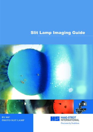
Slit Lamp Imaging GuideBX 900 PHOTO SLIT LAMP
PreambleOn August 3rd, 1911, Alvar Gullstrand introduced the first rudimentary model of the slit lampilluminator.An occasion of tremendous significance to ophthalmology had just taken place. Gullstranddescribed a device with the potential to advance the understanding of the eye and its problems asprofoundly as did the direct ophthalmoscope 50 years earlier. By 1916, Henker had developed apractical combination of Gullstrand's illuminator and Czapski's corneal microscope, marking thefirst major advance in methods of examining the external eye in more than a century. In 1936Comberg established the co-pivotal and iso-centric relationship between the microscope and slitilluminator and, in 1938, Goldmann’s collaboration with Haag-Streit produced the first par-focalinstrument which also featured the single control lever design in use to this day. Goldmann alsoinfluenced the shift to Köhler illumination, greatly improving the efficiency of the slit lamp illuminator, the very heart of this marvelous device.These significant milestones, with contributions froma host of other individuals, have coalesced into the highly sophisticated instruments that are placedat our disposal today. In light of such capabilities in instrumentation, it follows that our results inslit lamp examination and slit lamp photography will rest on the level of sophistication we applyto the practice of these challenging and stimulating art forms.Csaba L. Mártonyi, COPRA, CRAEmeritus Associate ProfessorUniversity of Michigan, Ann ArborBX User GuideThis guide is intended to assist all those who seek to capture images of the eye using the slitlamp to improve the quality of their photography by using simple to follow illumination diagrams and high quality image examples. We hope this book provides inspiration and motivation to anyone who is involved the art of documenting the unique properties and pathologiesof the eye and through Haag-Streit we offer a number of instruments to help you.The Haag-Streit BX900 slit lamp marries the latest imaging technology with the proven versatility, optical brilliance and build quality of the Haag-Streit tradition. The BX900 is the leadingslit lamp-imaging device that is designed to assist the Ophthalmic Photographer with hisdemanding job. Furthermore it will also provide a valuable asset for all Eye Cap Specialists whodemand the highest clinical and educational standards.Haag-Streit greatly appreciates and thanks all those who have contributed to this publicationwith special thanks to Cees van Beek of Leyenburg Hospital, Den Haag who provided many ofthe images.Steve ThomsonHaag-Streit AG
CONTENTSBX900 PHOTO SLIT LAMP4TECHNICAL DATA6PHYSICAL AND OPTICAL CONDITIONS7TYPES OF ILLUMINATION7STANDARD SETTING8ILLUMINATION AND EXPOSURE RNEA11ANTERIOR CHAMBER, CHAMBER ANGLE14IRIS, IRIS-ANGIOGRAPHY15LENS16VITREOUS17FUNDUS18
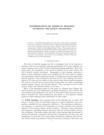
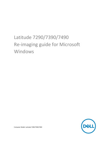
4BX 900 PHOTO SLIT LAMP1. Cable guide3122. Flash housing453. Flash intensity changerfor background illumination64. Objective tube75. Camera body896. Eye-piece with double crosshair reticle7. Mirror housing118. Background illumination9. Mirror and Diffusion filter1010. Cold light source11. Shutter release bar12. Photo control unit12The Haag-Streit Photo-Slit Lamp BX 900 is based on the Slit Lamp BQ 900 . It is therefore possible to use the same instrument both for ocular examination and documentation. A photo-slitlamp is a combination of a biomicroscope, and illumination system and the photo attachment.The Photo-Slit Lamp BX 900 and the Slit Lamp BQ 900 share the same microscope. The illumination system of the photo-slit lamp has in addition a flash unit and a background illumination. Two different light sources are available: the flash illumination and the modelling light. Onthe following page the different components will be explained.
51. The cable guide contains the high voltage cable for theflash light.2. The flash housing contains the flash tube. Firing the BX900trigger will simultaneously deliver a flash through the illumination system and, via a glass fibre cable, the fill background illumination while synchronising with the camerashutter.7. The background illumination is swivel-mounted on a horizontal level and is illuminated through two glass fibre cables.The flash fill light comes from the flash housing and the modelling light comes from the cold light source. The modellinglight is used to show where any reflection of the fill flash willfall.8. The cold light source is mounted under the table and it provides the background modelling illumination.3. The background illumination changer has seven settings: 100 % 10 % 50 % 5% 0% 25 % blue filterThese selections are only for the fill flash of the backgroundillumination. The modelling light is controlled by the coldlight source.4. The camera body is mounted on the top of the biomicroscopeallowing full visibility of the patient’s eyes from either side ofthe microscope. Not all cameras available on the market canbe used. Haag-Streit has selected a number of models and hasmade the necessary adaptations. The correct function of thephoto-slit lamp is guaranteed only by the use of cameras thatare recommended by Haag-Streit. A list of current cameramodels is available at: www.haag-streit.com. Note thatthe camera has to be in the «MANUAL» operating mode andthe shutter speed should be set to 1/90 sec. The recommendedISO rating for general use is 200 and colour temperature ofthe flash is 6000k but users have the option to apply othersetting as required.5. The 12.5x eyepiece with double cross hair reticule is insertedinto the right ocular of the microscope. This must be correctlyfocused for the user’s eye to ensure sharp images are captured. Note that this setting is not the user’s refractive error.6. The principal component of the Haag-Streit Photo-Slit LampBX 900 is the mirror housing with its built-in diaphragms.It mounts between the magnification changer and the binocular tube. When capturing an image all light is directed, viaa mirror, to the camera. This allows the maximum utilisationof the available light: 100% for the examination and 100% forthe image. The built-in diaphragm setting with five aperturesis applied automatically on image capture. For the apertureintervals: Step 1 largest aperture, Step 5 smallest aperture.The small knobs on each side of the mirror housing can beused during examination to quickly activate the diaphragmsto the pre-set position. This allows a preview prior to captureso that the image subject and depth of field may be checked.9. With the diffusion filter the slit beam can be covered allowing overview pictures with diffuse illumination.10. The shutter release bar is conveniently positioned in front ofthe joystick on the cross-slide. It can be used either right orleft-handed.11. The photo control unit is mounted under the left hand side ofthe table and has the main switch for the power supply. Onthe front side there are two switches and four error light indicators. With the main power switch it is possible to turn offthe entire electrical system of the slit lamp. The camera maybe turned off separately. The power switch on the front sideis only for the photo control unit. With the flash-intensityswitch in the high position, the flash light increases by oneaperture step. Optical and acoustic warning signals will beactivated in the case of an error when the shutter release baris pressed. Once the cause of the problem has been removed,press the shutter release bar and the optical warning signalwill be cancelled and the camera will be ready for use.
6TECHNICAL DATABIOMICROSCOPEMagnification ChangerOcular MagnificationRange of Adjusting OcularsReticleInter-pupillary Distance6.3 x 10 x 16 x 25 x 40 x12.5 x 8 to -8 dioptresright ocular52–78 mmSLIT LAMP ILLUMINATORSlit HeightSlit WidthSpotlightHorizontal ArcVertical ArcFiltersSlit Beam DiffuserLight Source Illumination DeviceLight Source Background Illumination1– 8 mm0–8 mm0.2, 1, 2, 3, 5, 8 mm diameter /- 90 5 , 10 , 15 , 20 blue, green (red free), N. D. 10%yes6V 4.5A TungstenHalogenPHOTO ATTACHMENTImage DeliveryObjective Tube Focal LengthLight Source Flash LightQuick Return Mirror 100 % light for examination orphotography170 mmnormal 200 Ws, high 400 WsDEPTH OF FIELDIMAGE AND MAGNIFICATION DATAdependent on magnification and apertureSetting atmagnificationchangerMagnificationExtent of depth of focus ( /- in mm)with apertureChip dimensionsSize of fieldin mmMagnification inplane ofthe chip24x36 mmMono15x22.5 mmMonoMagnification inplane ofthe chip24x36 mmStereo123456.3 x1.31.82.63.65.26.3 x0.63x38x5723.8x35.70.63x38x28.510 x0.50.711.4210 x1x24x3615x22.51x24x1816 x0.20.30.40.50.816 x1.6x15x22.59.4x14.11.6x15x1125 x0.10.10.150.20.325 x2.5x9.5x146x92.5x3.5x740 x0.050.050.050.10.1540 x4x6x93.88x5.64x6x4.5Values will be increased by 35% in transparent media of the eyesCircles: visible field of the eye-piece
7PHYSICAL AND OPTICAL CONDITIONSThe binocular examination of the eyes with the slit lamp takesplace in a three-dimensional space with great depth of field.Normal slit lamp imaging is a two-dimensional documentation with a very small depth of field. The difference betweenstereo viewing and monocular imaging can sometimes provetroublesome. However, viewing monocularly can help. Noteonly the image through the right eyepiece is recorded.The BX900 has a clear screen with a cross hair reticule. Theaccommodative abilities of the photographer’s own eye arenormally not noticeable during an examination: It is importantthat the photographer must establish the correct eye-piece setting (see page 5) to neutralise any accommodation. Only byviewing a sharp image of the reticule overlying a focused imageof the eye will sharply focused images be captured.The photographer’s view through the eyepieces is not the sameas the recorded image. Through the eyepieces a circular image isvisible whereas the image captured is rectangular (see page 6).The Haag-Streit BX900 has no measurements for the lightintensity and no automatic exposure system. It is therefore useful to take notes in the early stages of using the BX. Downloading images into EyeCap or a suitable image viewer willenable instant evaluation and will enable adjustments to bemade that optimise the image. The practical examples will help,but they are only starting-points.It should also be considered that the examiner’s attention isfocused on the details that are of interest and by selective viewing the brain suppresses certain artefacts. The camera howeverdoes not!TYPES OF ILLUMINATIONThe correct illumination will allow optimal recording of ocularpathology.DIFFUSE ILLUMINATIONThe slit lamp beam should be completely opened and coveredby the diffusing filter. The background illumination can be usedin conjunction with the slit illumination for more uniform lighting. The diffuse illumination is normally used for overview pictures with low magnification (10x and 16x).DIRECT FOCAL ILLUMINATIONDirect focal illumination refers to projecting the light on thesubject at the plane of focus. Unlike diffused light concentrated light penetrates transparent structures. With a centred slitbeam there is always direct focal illumination.INDIRECT ILLUMINATIONWith indirect illumination the light does not fall directly on thepathology. The slit beam is decentred and projected just adjacent to the subject area and it is illuminated by scattered internally reflected light.RETROILLUMINATIONRetroillumination is an indirect illumination too. Light reflected from the fundus or iris illuminates the pathology frombehind. If the slit beam is decentred and higher magnificationis used, unwanted reflections can be minimised.PHOTOGRAPHY WITH THREE-MIRROR CONTACTLENS OR 90-DIOPTER LENSWith these instruments there are more optical interfaces (air /glass and glass / cornea). All interfaces cause reflexes andtherefore it is better to take images without the backgroundillumination. Furthermore any scratches or damage to the lenswill increase the number of image artefacts.If the space between the diagnostic contact lens and the slit illuminator is very small, the background illumination can belocked in the centre position.
8STANDARD SETTINGThe BX900 has many different adjustments and its correct usecan give optimal illumination and exposure. It is advantageousto always start with a standard setting and to make adjustmentsafter each image captured.An example for a standard setting is the diffuse illumination:1. Main switch on, photo control unit POWER ON andcamera body on.2. After waiting a few seconds, set the flash intensity on HIGH.3. 100% Background illumination45 Angle between microscope and background illuminationSlit beam verticalSlit beam fully open (slit width and height)Slit beam centred (screw tightened)100% slit illumination (without filter)Slit beam covered with the diffusion filterAngle between microscope and illumination device 30 –45 Magnification 10xAperture 4 with a sensor rating ISO 2004. Define the image field, close the left eye (note the differencebetween eye-piece and photo tube picture)5. Focus control (eye-piece setting correct?)6. Capture Image.ILLUMINATION AND EXPOSURE SETTINGSThe following table shows the different settings of illumination and exposure adjustments. This table is also used for practical examples and will give a starting point.ISO:Flash Intensity:Background:Angle:Slit Beam:Filter:Angle:Magnification:Aperture:200high / normal100%, 50%, 25%, 10%, 0%, blue filter0 – 90 0 ( closed) to 8 mm ( full open)blue, red free (green), grey (10% N. D.), diffused0 – 90 ndIllumination:Moderate SlitBeam:Slit Beam withDiffused Filter:Wide Slit Beam:Slit BeamCentered:Slit BeamDecentered:Narrow SlitBeam:Microscope:
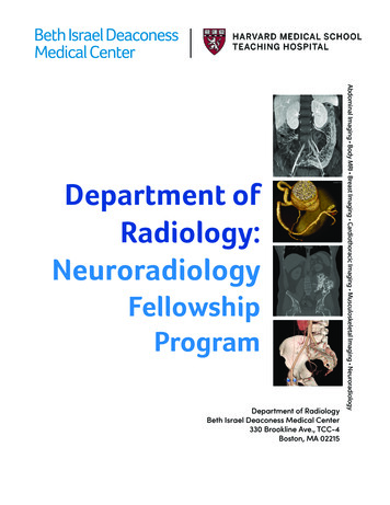
9OVERVIEWDIFFUSE ILLUMINATION WITH SLIT ILLUMINATION AND BACKGROUND ILLUMINATIONThe diffuse illumination with slit beam and background illumination gives a shadowfree illumination with natural colours and two light reflexes. This is most useful forlow magnification overview images.ISO:Flash Intensity:Background:Angle:Slit 0%30 –45 fully opendiffused30 10x16x4425x340x2200high100%30 –45 closed––10x16x4325x340x2DIFFUSE ILLUMINATION WITH BACKGROUND ILLUMINATION ONLYThe diffuse illumination with only the background illumination increases the contrast. The structures of the iris are more visible and there is only one light reflex.ISO:Flash Intensity:Background:Angle:Slit Beam:Filter:Angle:Magnification:Aperture:
10LIDSDIFFUSE ILLUMINATIONDiffuse illumination provides evenly balanced lighting.CONJUNCTIVAISO:Flash Intensity:Background:Angle:Slit 30 –45 fully opendiffused30 10x16x4425x340x2ISO:Flash Intensity:Background:Angle:Slit 30 –45 fully opendiffused30 10x16x5525x440x3ISO:Flash Intensity:Background:Angle:Slit %30 –45 0.1 mm–45 10x16x3225x240x1DIFFUSE ILLUMINATIONDiffuse illumination provides evenly balanced lighting. Exposure control is morevaried due to increased reflectivity.NARROW SLITA centred, narrow slit beam projected at a 45 angle demonstrates surface topographyand trans-illumination of the lesion. The background illumination gives the positionof the slit beam.
11INDIRECT ILLUMINATIONA moderately wide and decentred slit beam is projected just adjacent to the border ofthe lesion. The light penetrates conjunctiva and illuminates the clear fluid below. Inthe presence of blood or scar tissue, the light is absorbed.CORNEAISO:Flash Intensity:Background:Angle:Slit %30 –45 2–4 mm–decentred10x16x2225x140x1ISO:Flash Intensity:Background:Angle:Slit 0%30 –45 fully opendiffused30 10x16x4425x340x2ISO:Flash Intensity:Background:Angle:Slit –25%45 open10%60 –80 10x16x–425x340x2DIFFUSE ILLUMINATIONThis illumination technique can only be used in the presence of dense corneal pathologies because diffuse light does not penetrate very well through the cornea. Dilatingthe pupil can enhance pathology by creating a darker background.WIDE SLIT BEAM – TANGENTIAL ILLUMINATIONThis technique can provide more information as the oblique illumination is reflectedand refracted by the cornea and any pathology. Experiment with the illumination angleslit beam width for optimum results.
12MODERATE SLIT BEAM WITH SEPARATION OF ILLUMINATED EPITHELIUM AND ENDOTHELIUMThe moderate beam produces two different layers of illumination, one on theepithelium and one on the endothelium. Note the corneal changes are closer tothe posterior reflection and therefore they lie deep in the cornea.ISO:Flash Intensity:Background:Angle:Slit –25%30 2–3 mm–45 10x16x–325x340x2ISO:Flash Intensity:Background:Angle:Slit ��10%45 0.1 mm–45 –60 10x16x–125x140x–ISO:Flash Intensity:Background:Angle:Slit –1–2 mm–decentred10x16x–225x140x1NARROW SLIT BEAM – OPTICAL SECTIONINGA narrow focal slit beam is projected at a 45 to 60 angle. It cuts an optical sectionthrough the cornea like a knife. With this technique it is possible to locate the layerof the pathological changes. These examples demonstrate endothelial and surfacepathology.DIRECT RETROILLUMINATION FROM THE IRISA moderate slit beam is decentred and angled to project onto the iris directly behindthe pathology. The light reflects and backlights the cornea. If there is some cataractpresent the lens can also be used to reflect light directly onto the area of interest.
13INDIRECT RETROILLUMINATION FROM THE IRISThe moderate slit beam is now decentred even more and angled to project onto theiris adjacent to the area behind the area of interest. The background is dark and theedges of non-pigmented lesions are well defined by the diffuse light reflecting fromthe iris.ISO:Flash Intensity:Background:Angle:Slit ��10%–1–2 mm–decentred10x16x–225x140x1ISO:Flash Intensity:Background:Angle:Slit –2 mm–decentred10x16x–225x140x1ISO:Flash Intensity:Background:Angle:Slit ue filter30 fully openblue filter60 –80 10x16x3325x240x1SCLEROTIC SCATTERThe wide decentred slit beam is projected onto the limbus. The light striking the limbus is internally reflected through the corneal tissue like a fibre optic. Corneal changesor abnormalities can be visualised by reflecting the scattered light. Careful post capture cropping can enhance images.TOPICAL ADMINISTRATION OF SODIUM FLUORESCEINSodium fluorescein is applied gently to the bulbar conjunctiva. The patient shouldblink once or twice for the dye to be dispersed over the eye. If the epithelium of theconjunctiva or the cornea is damaged, the fluorescein stains the underlying tissue. Theremaining dye fluoresces a yellow green colour when excited by the blue light. Healthyepithelium does not stain.Rose Bengal is a dye that can be used to demonstrate abnormal epithelial cells. Thedye is applied like sodium fluorescein and is usually imaged using direct white light.
14ANTERIOR CHAMBER, CHAMBER ANGLEAQUEOUS FLARE – TYNDALL’S PHENOMENONCells, pigment or proteins in the aqueous humour reflect the light like a faint fog. Tovisualise this the slit illuminator is adjusted to the smallest circular beam and is projected through the anterior chamber from a 42 to 90 angle. The strongest reflectionis possible at 90 .ISO:Flash Intensity:Background:Angle:Slit –25%30 0.1–1 mm–50 10x16x–125x140x1ISO:Flash Intensity:Background:Angle:Slit –2 mm–10 10x16x–525x540x4CHAMBER ANGLE – GONIOPHOTOGRAPHYThe desired mirror of the gonioscopy lens is positioned opposite to the area of pathology. A wide slit beam is projected in the desired mirror from a near coaxial position tothe biomicroscope. Light reflections can be eliminated by tilting the lens.
15IRIS, IRIS-ANGIOGRAPHYWIDE SLIT BEAM - TANGENTIAL ILLUMINATIONThe wide slit beam is projected at an oblique angle of 80 – 90 onto the iris. This illumination creates strong shadows and the surface texture is enhanced. If the headrestdoesn’t allow a wide oblique angle it is sometimes necessary to turn the patient’s heada little away from the light.ISO:Flash Intensity:Background:Angle:Slit –10%45 open–80 10x16x5525x440x4ISO:Flash Intensity:Background:Angle:Slit –10%45 Ø 1–2 mm–coaxial10x16x–225x140x1ISO:Flash Intensity:Background:Angle:Slit ue filter45 openblue filter45 –60 10x16x–125x–40x–IRIS TRANSILLUMINATIONThe slit illuminator is positioned coaxially to the biomicroscope and adjusted to provide a small circular beam of light. This beam is projected through the pupil whichshould be at mid dilation. The light reflects from the fundus and backlights the iris.Normally the iris pigment absorbs the light, but pigmentation defects let the red fundus light pass through.IRIS ANGOIGRAPHYThe illumination technique of the iris angiography is like the tangential illuminationwith the background illumination opposite the slit beam. Both slit illuminator andbackground illumination have a blue excitation filter. The yellow barrier filter is positioned between the magnification changer and the mirror housing. The barrier filteronly works on the image from the right eyepiece which is directed to the camera. Control of the focus of the image during the angiography is possible through the left eyepiece.
16LENSNARROW SLIT BEAM – OPTICAL SECTIONINGA narrow focal slit beam is projected at a 45 angle to the lens as an optical section ismade. Because of the problematic depth of field it is not possible to photograph theentire lens section in focus. It is therefore necessary to focus on the anterior or the posterior lens surface.ISO:Flash Intensity:Background:Angle:Slit %45 0.1 mm–45 10x16x–125x140x–ISO:Flash Intensity:Background:Angle:Slit %45 2–4 mm–45 10x16x–225x240x1ISO:Flash Intensity:Background:Angle:Slit %45–60 2–6 mm–45 –60 10x16x–225x240x1MODERATE SLIT BEAM – DIRECT ILLUMINATIONA moderate slit beam is projected at a 45 angle to the lens pathology and is directlyilluminated. Dilation of the pupil is required for effective imaging.MODERATE SLIT BEAM – TANGENTIAL ILLUMINATIONA moderate to wide slit beam is projected at an angle greater then 45 degrees to provide oblique tangential illumination that can enhance detail by providing shadows.Pupil dilation will aid this illumination technique.
17RETROILLUMINATION FROM THE FUNDUS – RED-REFLEX PHOTOGRAPHYThe slit illuminator is positioned in an almost coaxial position with the biomicroscope.A wide slit beam is decentered and adjusted to a half circle by using the slit width andheight controls. The decentred slit beam is projected near the pupil margin through adilated pupil. Careful composition can minimise the direct reflection.VITREOUSISO:Flash Intensity:Background:Angle:Slit –2 mm–decentred10x16x–225x140x1ISO:Flash Intensity:Background:Angle:Slit –10%45 0.1–1.0 mm–45 10x16x–125x140x–NARROW SLIT BEAMWithout diagnostic lenses it is only possible to examine and to document the anteriorpart of the vitreous. Anterior Vitreous pathology can be seen with a narrow slit beam.Only when the dioptric power of the eye is reduced is it possible to focus moreposteriorly.
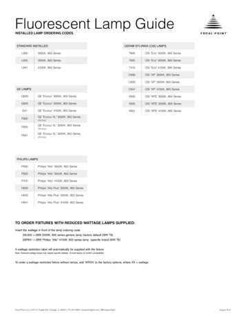
18FUNDUSCENTRAL RETINA PHOTOGRAPHS WITH THE THREE-MIRROR CONTACT LENSThe posterior pole can be documented with the centre of the three-mirror contact lens.The slit lamp illuminator is in an almost coaxial position. If the slit beam is too widedisturbing light reflections may occur.ISO:Flash Intensity:Background:Angle:Slit –2 mm10%5 –10 10x16x–225x140x1ISO:Flash Intensity:Background:Angle:Slit –2 mm10%5 –10 10x16x–225x140x–CENTRAL RETINA PHOTOGRAPHS WITH A 90-DIOPTER LENSDiagnostic contact lenses are sometimes contraindicated after intra-ocular surgery. Insuch cases the use of the 90- dioptre lens is necessary. The handling of this lens is moredifficult because there is no physical contact with the eye. A moderate slit beam in thealmost coaxial position gives the best results.
Recommended ReadingClinical Slit Lamp Biomicroscopy andPhoto Slit Lamp BiomicrographyMartonyi, Bahn & MeyerTime One Ink, Ltd.Sedona, AZThis book is currently in revision.An expanded Third Edition isexpected late 2005.Copies of the Third Edition and other booksof interest to the Ophthalmic Photographer canbe found at;http://www.twinchimney.comPhotos by:Cees van BeekLeyenburg Hospital, Den Haag, NetherlandsTarek ShaarawyUniversity Hospiral of Geneva, SwitzerlandSteve ThomsonHaag-Streit, Bern, Switzerland
1500.7200668.02000 / 09.05-2.5HAAG-STREIT AGGartenstadtstrasse 10CH-3098 Koeniz/SwitzerlandPhone 41 31 978 01 11Fax 41 31 978 02 82info@haag-streit.chwww.haag-streit.com
Light Source Illumination Device 6V 4.5A Tungsten Light Source Background Illumination Halogen PHOTO ATTACHMENT Image Delivery Quick Return Mirror 100% light for examination or photography Objective Tube Focal Length 170 mm Light Source Flash Light normal 200 Ws, high 400 Ws DEPTH OF FIELD dependent on magnification and aperture