Transcription
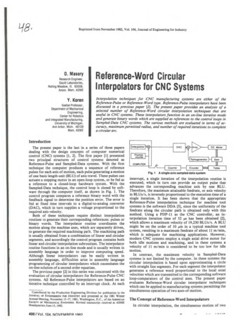
Reprinted fror:n November 1982, Vol. 104, Journal of Engineering for Industry0. MasoryResearch Engineer,Gould Laboratories,Rolling Meadow, Ill. 60008,Assoc. Mem. ASMEY. KorenGoebel Professor,Department of MechanicalEngineering,Cenler for Roboticsand Integrated Manufacturing,University of Michigan.Ann Arbor, Mich. 48109Mem.ASMERteference-Word CircularInterpolators for CNC SystemsInterpolation techniques for CNC manufacturing systems are either of theReference-Pulse or Reference-Word type. Reference-Pulse interpolators have beendiscussed in a previous paper [2]. The present paper provides an analysis of aselecte number of Reference-Word circular interpolation techniques that areus.efu/ m CNC systems. These interpolators junction in an on-line iterative modeand generate binary words which are supplied as references to the control/oops inSampled-Da a CNC sys.tems. T e various methods are evaluated in terms of accu,racy, maxzmum permztted radzus, and number of required iterations to completea circular arc.IntroductionThe present paper is the last in a series of three papersdealing with the design concepts of computer numericalcontrol (CNC) systems [1, 2]. The first pape:r [1] presentedtwo principal structures of control systems denoted asReference-Pulse and Sampled-Data systems. With the firsttechnique the computer produces a sequenc:e of referencepulses for each axis of motion, each pulse gene:rating a motionof one basic length-unit (BLU) of axis travel. These pulses canactuate a stepping motor in an open-loop system, or be fed asa reference to a closed-loop hardware system. With theSampled-Data technique, the control loop is closed by software through the computer itself, as shown in Fig. 1. Thecontrol program compares a reference binary word with thefeedback signal to determine the position error. The error isfed at fixed time intervals to a digital-to-analog converter(DAC), which in turn supplies a voltage proportional to therequired axis velocity.Both of these techniques require distinct: interpolationroutines to generate their corresponding references: pulses orbinary words. The interpolator routine coordinates themotion along the machine axes, which are separately driven,to generate the required machining pa!h. The machining pathis usually obtained from a combination of linear and circularsegments, and accordingly the control program contains bothlinear and circular interpolation subroutines. Tlhe interpolatorroutine functions in an on-line mode and is usually written inassembly language in order to improve computing speed.Although linear interpolators can be easily written inassembly language, difficulties arise in assembly languageprogramming of circular interpolators which necessitates theon-line solution of a second order equation.The previous paper [2] in this series was concerned with theevaluation of circular interpolators for Reference-Pulse CNCsystems. All Reference-Pulse interpolators are based on aniterative technique controlled by an interrupt dock. At eachContributed by the Production E ngineering Division for publication in theJOURNAL OF ENOINEERINO FOR INDUSTRYA single·axis sampled·data systemand presented at. the 1981 WinterAnnual Meeti ng, November 15- 17, 1981, Washington, D.C., of the AMERJCANSOCIETY OF MECIIANICAL ENGINEERS. Revised manuscript received at ASMEHeadquarters June 15,1982.400 I Vol. 104. NOVFMR FRFig. 1interrupt, a single iteration of the interpolation routine isexecuted, which in turn can provide an output pulse thatadvances the corresponding machine axis by one BLU.Therefore, the maximum attainable feedrate, or axis velocityin BLUs/s, is inversely proportional to the execution time of asingle iteration. It has been shown that the appropriateReference-Pulse interpolation technique for machine toolsystems is the software DDA [3], since the uniformity of thefeedrate along the circular path is obtained only with thismethod. Using a PDP-11 as the CNC controller, an interpolation iteration time of 52 p.5 has been obtained [2],which allows a maximum velocity of 19,230 BLUs/s. A BLUmight be on the order of 10 Jtm in a typical machine toolsystem, resulting in a maximum feedrate of about 11 m/min,which is adequate for machining applications. However,modern CNC systems employ a single axial drive motor forboth idle motions and machining, and in these systems avelocity of 11 m/min is considered to be too low for idlemotion.In contrast, the maximum velocity in Sampled-Datasystems is not limited by the computer. In these systems thecircular interpolation is based upon approximating a circlewith straight line segments. For each segment the interpolatorgenerates a reference word proportional to the local axialvelocities which are transmitted to the corresponding softwareloop-comparators of the control axes. The present paperevaluates Reference-Word circular interpolator techniqueswhich can be applied to manufacturing systems permitting thesimultaneous operation of two axes-of-motion.1Q.R?The Concept of Reference-Word InterpolatorsIn circular interpolation, the simultaneous motion of two
ycoordinates of the successive point X(i 1), Y(i 1) according to equation (6). The segment lengths are:DX(i) X(i l) - X(i) (A -l)X(i)-BY(i) (7)DY(i) Y(i l) - Y(i) (A - l)Y(i) BX(i)and the corresponding velocities are:Vx (i) VoDX(i)IDS(i)Vy (i) V0 DY(i)IDS(i)(8)where UL ---------------- ------ -- Fig. 22 The values obtained from equation (7) are the incremental positions, and those of equation (8) are thevelocities, or the reference-words, for the present segment.These values are supplied to the software control loops.XDefinitions for the reference·worcl techniqueaxes generates a circular arc at a constant t:angential velocity,or feedrate, V0 The axial velocities satisfy the followingequations: V0sin O(t)Vy (t) V0 cos O(t)Vx (t)(1)3 Upon completion of the segment, the routine incrementsthe coordinates X(i) and Y(l) .Since the angle a is relatively small,,the chord length DS canbe approximated by its arc length Ra and the calculation ofthe velocities Vx and Vy can be simplified to:Vx(i) K DX(i)(9)whereVy (i) K DY(i)O(t) (V0 1R)tand is the radius of the circular arc.The velocity components Vx and Vy are: computed by thecircular interpolator and are supplied as r-eference inputs tothe computer closed-loops. The circle generated in this case isactually comprised of straight line segments . At the beginningof each segment the references are supplied by the interpolator and the end of the segment is located with the aid ofa feedback signal. Increasing the number of these segmentsimproves the accuracy of the generated cilrcle, but increasesthe number of iterations, thus requiring mo re computer time.The optimal number of segments is the smallest one whichmaintains the path error within the required limit of one BLU.Each iteration of the algorithm corresponds to an angle a,as illustrated in Fig. 2. The choice of the a:ngle a depends onthe interpolation method. All of these methods employ thedifference equation:cosO(i 1) AcosO(i) - BsinO(i)(2)sinO(i 1) AsinO(i) Bc·osO(i)where the coefficients A and B are given by:A cosaB sina(3)where K V0 / Ra. The parameter K is a constant, which iscalculated only once for each circle, and consequently thereference words are actually proportional to the segmentlengths.Approximation of a circle by straight line segments causestwo types of errors as illustrated in Fig. 3:(a) Radial error ER, due to the truncation effects:ER (i) R(i) - R ,lX2 [i) .f. ([} -Rwhere R is the required radius.(b) Chord height error EH defined by:EH (i) R - R (i) cos(a/2)(4)The corresponding segment is terminated at the point X(i 1),Y(i I) which is approximated by:X(i 1) R(i)cosO(i 1)(5)Y(i 1) R(i) sinO(i 1)Substituting equation (2) into (5) yields:X(i l) AX(i) -BY(i)(6)Y(i 1) AY(i) BX(i)Equation (6) is the basic relationship which permits thecalculation of a successive point based on the present one.The main differences between the variious interpolationmethods are in the determination of a and in approximationof the coefficients A and Bin equation (3). Once the angle a ischosen , the interpolator routine proceeds, lfor each iteration,as follows:1 At each point X(i), Y(i) the interpolator calculates theJournal of Engineering for Industry(II)Equation (10) is explicitly obtained using the approximatedvalues of A and B, which causes the truncation error in theradius. Since the algorithms use an iterative technique, thiserror is accumulated with time. The effect of the truncationerror ER at the ith iteration can be approximated by (seeAppendix 1):(12)ER(i) i(C - l)RwhereC .JAT lfiandO(i l) O(i) a(10)Equation (12) shows how the truncation error increases withthe number of iterations. The largest circular arc produced bya single instruction in NC systems is a quarter of a circle. Thecompatible number of iterations is:N 1rl2a(13)Upon completing this number of steps the error ER reaches itsmaximum value:(14)ERmax (7r/2a)(C-1)RBy contrast, the error EH is not cumulative. Using the formulacos(a/2) .J(l cosa)/2 .J(l .Af7i(15)in equation (11), yields:EH(i) R-R(i) .J(l A)/2.(16)The angle a is selected so that either the error ER or EHNOVEMBER 1982, Vol. 104/401
reaches a maximum value of one BLU. In addition to theTable 1angle ex, the interpolator is given the coordinates of the initialMaximum radius in IEMn[bits]point [X(O), Y(O)] and the required feedrate V0 Theseparameters are obtained from the part-program for eachcircular arc.Several interpolators applying the reference-word methodare now discussed and their relative features are compared.Q15233181316pRm!BLUs]71015409525532767The actual average A which is used in equation (27) is givenby:Euler MethodThe Euler method is based upon a first-order Taylor seriesexpansion to equation (3) which provides the simplest approximation:A I;B cx(17)The basic equations of the algorithm are obtained by substituting for A and Bin equation (7):DX(i) - aY(i)DY(i) cxX(i)(18)Substitution of equation (18) in (9) gives the requiredvelocities:Vx(i) -(Vo!R)Y(i)Vy (i) I2a2X(i) (1 a) Y(i)or at angle of 8(29) 1rl4 and the corresponding error is:a4ERmax (30)RSince ER should not exceed one unitSince the series expansion is truncated after the frrst term, theaccuracy of the Euler method depends mainly on this truncation error ER rather than on the chord error EH. Themaximum error is obtained by substituting equation (17) intoa 41R(31)The number of iterations required to produce a quarter of acircle as obtained from equation (13) is:(14):N 1rRI8ERmax (1r/2a)( - 1)R(20)For small a, equation (20) can be approximated by:ERmax (?r/4)aR(21)which allows for calculating the value of a. To satisfy theaccuracy requirement, the maximum permitted error is oneBLU and the corresponding angle is:a 4! (?rR)(22)Consequently, the number of iterations required to Complete aquarter of a circle is obtained from equation (13):N R/8(23)The improved Euler method (IEM) [3] also us.es the approximation (17) but it applies the calculated value of X(i I)to determine the present value of Y(i 1). With thismodification, equation (6) becomes:X(i l) AX(i) - BY(i)Y(i I) A Y(i)(24) BX(i 1)and with substitution of A and B from (17) the mainequations of the (IEM) algorithm are obtained:X(i l) X(i)-aY(i)(25)Y(i I) Y(i) cxX(i I)The segment lengths as defined in equation (7) are:DX(i) -a Y(i)DY(i) cxX(i I)X(i) - aY(i) (l-cx )Y(i) cxX(i)2402/ Vol. 104, NOVEMBER 19822m ' 2 C!::.R(33)The power m is the smallest integer which satisfies equation(33) and is obtained by SHIFT operations. Thus, a completeimplementation of the IEM algorithm is achieved by basicassembler instructions, without the necessity for either afloating-point unit (FPU) or multiplication operations.In spite of the attractive features of the IEM, special care isneeded to avoid introducing a new truncation error that canarise from the right-shifts used in cxX and aY. To avoid thetruncation error, then-bit word is divided into two parts. Onepart is q bits long and stores the radius. The other part is p bitsand stores the error. In the IEM, the maximum ER (of oneunit) occurs at 8 1!'14 or when l/2N iterations have beencompleted. Thus, the condition:(26)-12The improvement as compared with the previous method isillustrated by deriving the explicit expression for Y(i 1) in thesecond equation of (25):Y(i I)(32)which is less than with the Euler method by a factor of 1r (seeequation (23)).Although the algorithms of the Euler and Improved Eulermethods are relatively simple, they cannot be implementedwith basic assembler instructions such as ADD and SHIFT.The computational difficulties arise in calculating the angle aand in performing multiplications cxX and a Y. With the Eulermethod, part of the difficulty in calculating the angle a is withusing the factor ?f (equation (22)), which is not needed withthe IEM (equation (31)). The second difficulty can be overcome by expressing the angle a in powers of 2, i.e., a 2-m,thereby permitting the use of SHIFT operations rather thanmultiplications. In this case the angle a is calculated by:a 2 - m s4/RorImproved Euler MethodX(i I)(28)rather than the value of I which is used for approximation ofcosa in the Euler method. Therefore, a better approximationof the coefficient A is achieved with the IEM without anyadditional computational effort.The error ER reaches its maximum value for particulariteration that satisfies the condition (see Appendix 2):(19)(V0 1R)X(i)12-[I (1 - a 2 )] I- -N 2P(34)guarantees that the truncation error is less than one unit. Therelationship between the maximum permitted radius Rm andthe word length n can be determined through the equation:(27)n q p log2 Rm log 2 ( N)(35)Transactions of the ASM E
Table 2 Maximum radius in 151The error EH is equation (11) is obtained by substitution forA, which yields:!EH(I) R -R (i)j1-a 2 R - R (i) (a2 /8)R (i) (43)Since the error caused by the truncated series (39) leads to anincreased radius with each step, the maximum value of EH isobtained at the first iteration, for R ( i) R, which yields:Fig. 3Errors in the generated circle(44)Substituting for N from equation (32) gives:n 2log 2 Rm log 2 1r- 4(36)A comparison of two errors in equations (42) and (44) showsthatand since Rm 2qERmax Iq n 1.22(37)Table 1 gives the maximum allowable radius in BLU's fortypical length of computer words (one bit is reserved as a signbit):In practice only the last line in Table 1 wo uld give sufficiently large radii in CNC systems. Therefore, a double-oreven triple-precision word technique will be required in thecontrol computer. Note that since in the Euler method thenumber o f iterations are greater than in the IEM and themaximum error appears at the end of the arc, the equivalentformula to (37) is:q I2n-0.15(38)which means that the maximum permitted radius in practice iseven smaller, and the Euler method is useless for CNC applications.2EHmax(45)which means that for an angle a which satisfies a 2/7r, theerror EH is the dominant one. In this case the angle a isdetermined from equation (44). For EHmax equal to one BLUa v8/R(46)In this case a 2!1r is satisfied for R 20 BLUs, which coversvirtually all practical systems (e.g., if lBLU 10J.Lm,R 0.2mm). The number of iterations to complete a quarter of acircle is:(47)The algorithm given by equations (40) and (41) requires adetermination of a and a 2 Expressing these values in powerof 2 avoids the use of floating-point unit [5]:(48)orTaylor MethodFor the Taylor method [4] the coefficients A and B inequation (3) are evaluated by the truncated series:1A l- - a2 B a(39)2'Using these values, the basic equations of the algorithm arederived. The corresponding segment lengths are obtainedfrom equation (7):DX(i)I - -DY(i) - -212a 2 X(i) - aY(i)(49)Again, the power m is determined by SHIFT operations, andall multiplication instructions in the algorithm are executed inthe same way. Therefore, the Taylor method can be implemented by using basic assembler instructions.The relationship between the maXimum radius and theword-length for the Taylor method is:(40)and since R 2q:a 2 Y(i) aX(i)q and the velocities obtained from equation (9):Vx (i) -(Vo!R)[ aX(i) Y(i)JVy (i) (V0 /R)[ - aY(i) X(i)](41)The maxim um value of the error ER is calculated! according toequation (14):ERmax :2'TrCi(J1 ! a4-1)R 1rRa3 ! !6Journal o f Engineering for Industry23n 0.56(51)Examples illustrating the dependence of the maximum radiuson the word length are given in Table 2. The last two cases inTable 2 are practical for CNC systems.In reference [4] the Taylor method algorithm was applied toa CNC system controlled by a PDP-8 computer using a tripleprecision word. Successive points along the circular arc werecomputed at the rate of 1.4 millisecond per point. The interpolator occupied 600 (12 bit) words of core storage.Tustin Method(42)The Tustin method [6] is based on an approximateNOVEMBER 1982, Vol. 104/403
Table3 Simulation results for R 10,000 BLU'syMethodNEulerIEMTaylorTustinITMrelationship between the derivative operators and the discretevariablez:(52)Using the Tustin approximation yields the following relationsfor cosa and sin a, or A and B:1 - (a/2) 2aA I (a/2)2 ; B 1 (a/2)2(53)These approximations can be used to generate circular interpolation for CNC systems. Substituting these values of Aand B into equations (7) and (9) gives the basic equations ofthe proposed algorithm: -DY(i) 21l (a/2) 21[l (a/2) 2a X(i) a Y(i)]2.[ 2-V0Vx(I') - R[l (a/2)2]0VY ( I') R[l V(a/2)2][[-X(')TaY( ')I IY(. ]1)FPU4hrR.,?R / 8IEMFPU or ASL4/R1fRI8TaylorFPU orASL.Jf1R .JRT2TustinFPU./SiR .fR/2ITMFPU4/VR.!!.{R4481) 4/VRTherefore, the angle a is increased by a factor ofdecreasing the number of iterations to: X(')]IN .!!. VRER (i) 0(56)Since the error ER is identically zero, the angle 01 is prescribedby the error EH given in equation (16). For R (i) R:(62)Vi(63)8Obviously the Tustin methods require considerably morecalculations than the previous methods. Basic assemblerinstructions are insufficient to handle the routine and an FPUis a necessity.Comparison and DiscussionREH R - - .,.--./l (a/2)2which can be approximated for small a by:(57)al(58)EH -R2a 8The angle a is derived by equating the error EH toO one unit:(59)a ./8 /(R - 1) ./8/ Rwhich is identical to equation (46).Improved Tustin MethodThe Tustin method yields an ER of zero. From a practicalpoint of view in manufacturing systems we choose themaximum error equal to one BLU . Therefore th e method canbe improved by increasing the angle a [7). From Fig. 4 theangle a is evaluated using equation (15): -R-- ./2/(1 A) .Jl (a/2)2 1 404/ Vol. '104, NOVEMBER 1982Euler(55)The truncation error is found by substituting equation (53)into (12) which shows that:-1.5001.6521.4281.6811.405TableS Features of reference-word interpolatorsMethodProgrammingaNa ./16/(R -Ta- 9so that the angle a is:.R l401.0081.0020.0711.0161.029(54)Y(i) o:X(i) ']25656PracticalERmaxEHmaxTable4 Simulation results for R 250 L13 ---------------L------ xFig. 4 Circle generation by the Improved Tustin MethodDX(i)123313928SimulationERmaxEHmax8(61)The interpolation methods requmng an FPU weresimulated for R 10000 BLU units to produce a quarter of acircle. The results are presented in Table 3, where N is thenumber of iterations and the errors are given in BLUs.The errors ERmax and EHmax calculated during thesimulation of the methods, are listed in the third and fourthcolumns of Table 3. In a real system, however, the DACs andthe position counters can only use integer numbers, so thereference word must be an integer. This means that DX, DY,Vx, and Vy must be rounded off to the closest integer valuewhich increases the error. The maximum errors ERmax andEHmax for a real system are listed in the fifth and sixthcolumns of Table 3. In this example, for real systems, theinterpolation methods generate errors in the range of I to 2BLUs. In order to limit the error to 1 BLU the angle a shouldbe decreased. It can be seen that the Improved Tustin Methodwill generate an arc with the fewest number of iterations.In order to compare assembly language (ASL) with thefloating-point unit (FPU) methods, a simulation was performed for producing a 90 degree arc with a radius of 250units. The results shown in Table 4 indicate that for anTransactions of the ASME
algorithm programmed with assembly instructions, theTaylor method is the best. The number of iterations requiredto complete! the arc by this method is considerably smallerthan the number needed with IEM, while the erro rs are alwayswithin the required tolerance of one BLU.Finally, the main features of the various algorithms havebeen summarized in Table 5.The interpolators of Table 5 which require an FPU willrequire more computer storage and have reducc d computerspeed than those implemented with ASL. From Table 5 it canbe seen that if an FPU is available, the Improved TustinMethod (ITM), which has been introduced in the presentpaper, is the favorite. This method produces a circle using thefewest iterations and guarantees the required accuracy. Thecomputation of the parameters A and Bin equatiion (53) doesnot cause any difficulties since an FPU is used.If an FPU is not available, or if implementation ofassembly language is preferred, then the Taylor method [4, 5]should be applied. With this method the maximum allowableradius is much larger than with the IEM (see Tables 1 and 2),and the number of iterations required to complete the arc issmaller by a factor of .JR/2.Acknowledgment(Al-l)where(Al-2)By successively using equation (Al-I), as the interpolationproceeds, assuming that the initial point lies on the circle[R(O) R], one obtains:R(i) C;R(Al-3)The radial error ER in the ith step is determined fromequation (10) and equation (A1-3):ER(i) (C; -l)R(A1-4)Since the value of C is close to 1, equation (Al-4) is approximated by:ER(i) i(C-l)R(Al-5)APPENDIX2Defining:M(i) R(i 1) - R(i) .JX'-(i I) f2(i 1) -.JX'- (i) The authors would like to thank Professors S. Malkin andG. Ulsoy for their helpful comments.APPENDIX1Summing the squares of both sides of equation t(6) gives:Journal of Engineering for Industry(A2-1)The radial error ER at the jth step is derived by summingthe incremental errors M(1), or by integrating along the arcs:ReferencesI Koren, Y., "Design of Computer Control for Manufacturing Systems,"ASME JOURNAL OF ENGINEERING FOR INDUSTRY, Vol. 101, Ne . 3, Aug. 1979,pp. 326-332.2 Koren, Y., and Masory, 0., "Reference-Pulse Circular ltnterpolators forCNC Systems," ASME JOURNAL OF ENGINEERING fOR INDUSTRY, Vol. 103, No.I, Feb. 1981, pp. 131-136.3 Koren, Y., "Interpolator for a CNC System," IEEE Trans. on Computers, Vol. 25, No. I, Jan. 1976, pp. 32-37.4 Bergren, C., "A Simple Algorithm for Circular Interpolation," ControlEngineering, Sept. 1971, pp. 57-59.5 Musse, J. , Veron, M., Lepage, F., and Drapier, J., "High PerformanceTool Path Interpolator for CNC System," CIRP Manufacturintg Systems, Vol.7, No. I , 1978. (Presented in the 9th CIRP Int. Sem. on ManufacturingSystems.)6 Cadzow, J . A., and Martens, H. R., Discrete-Time and Computer ControlSystems, Chapter9, Prentice-Hall, New Jersey, 1970.7 Koren, Y., Computer Control of Manufacturing Systems, Chapter 5,McGraw-Hill, New Y6rk, 1983.f2 (i)ERU) tM(i) iM·ds(A2-2)i OThe maximum error ERmax is obtained by equating the firstderivative of equation (A2-2) to zero:dER- M(i) 0(A2-3)dsNamely, at R (i 1) R (i)Using the definition of equation (A2-1) we see that themaximum radial error occurs when(A2-4)Xl(i 1) f2(i I) X'- (i) f2 (i)Substitution of equation (25) into (A2-4) yields(A2-5)2[X(i) -X(i l)]Y(i)/a X'-(i 1) f2 (i)Substituting for X(i 1) from equation (24) into the left-sideterm of equation (A2-5) gives Y(i) X(i 1), orX(i) Y(i) aY(i)(A2-6)NOVEMBER 1982, Vol.104/405
ASME Rteference-Word Circular Interpolators for CNC Systems Y. Koren Goebel Professor, Department of Mechanical Engineering, Cenler for Robotics and Integrated Manufacturing, University of Michigan. Ann Arbor, Mich. 48109 Mem.ASME Interpolation techniques for CNC manufacturing systems are