Transcription
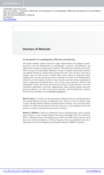
TC 9-524Chapter 7LATHESThe lathe is a machine tool used principally for shaping articles of metal (and sometimes wood or other materials) by causingthe workpiece to be held and rotated by the lathe while a tool bit is advanced into the work causing the cutting action. The basiclathe that was designed to cut cylindrical metal stock has been developed further to produce screw threads. tapered work. drilledholes. knurled surfaces, and crankshafts. The typical lathe provides a variety of rotating speeds and a means to manually andautomatically move the cutting tool into the workpiece. Machinists and maintenance shop personnel must be thoroughly familiarwith the lathe and its operations to accomplish the repair and fabrication of needed parts.TYPES OF LATHESLathes can be divided into three types for easy identification:engine lathes, turret lathes, and special purpose lathes. Smalllathes can be bench mounted, are lightweight, and can betransported in wheeled vehicles easily. The larger lathes arefloor mounted and may require special transportation if theymust be moved. Field and maintenance shops generally use alathe that can be adapted to many operations and that is not toolarge to be moved from one work site to another. The enginelathe (Figure 7-1 ) is ideally suited for this purpose. A trainedoperator can accomplish more machining jobs with theengine lathe than with any other machine tool. Turret lathesand special purpose lathes are usually used in production orjob shops for mass production or specialized parts. whilebasic engine lathes are usually used for any type of lathework. Further reference to lathes in this chapter will be aboutthe various engine lathes.7-1
TC 9-524ENGINE LATHESSizesThe size of an engine lathe is determined by the largestpiece of stock that can be machined. Before machining aworkpiece, the following measurements must be considered:the diameter of the work that will swing over the bed and thelength between lathe centers (Figure 7-1 ).CategoriesSlight differences in the various engine lathes make it easyto group them into three categories: lightweight bench enginelathes, precision tool room lathes, and gap lathes, which arealso known as extension- type lathes. These lathe categoriesare shown in Figure 7-2 Different manufacturers may usedifferent lathe categories.7-1LightweightLightweight bench engine lathes are generally small latheswith a swing of 10 inches or less, mounted to a bench or tabletop. These lathes can accomplish most machining jobs, butmay be limited due to the size of the material that can beturned.PrecisionPrecision tool room lathes are also known as standardmanufacturing lathes and are used for all lathe operations,such as turning, boring, drilling, reaming, producing screwthreads, taper turning, knurling, and radius forming, and canbe adapted for special milling operations with the appropriatefixture. This type of lathe can handle workplaces up to 25inches in diameter and up to 200 inches long. However, thegeneral size is about a 15-inch swing with 36 to 48 inchesbetween centers. Many tool room lathes are used for specialtool and die production due to the high accuracy of themachine.
TC 9-524GAP OR EXTENSION-TYPE LATHESGap or extension-type lathes are similar to toolroom lathesexcept that gap lathes can be adjusted to machine largerdiameter and longer workplaces The operator can increase theswing by moving the bed a distance from the headstock,which is usually one or two feet. By sliding the bed awayfrom the headstock, the gap lathe can be used to turn verylong workplaces between centers.LATHE COMPONENTSEngine lathes all have the same general functional parts,even though the specific location or shape of a certain partmay differ from one manufacturer The bed is the foundationof the working parts of the lathe to another (Figure 7-3).The main feature of its construction are the ways which areformed on its upper surface and run the full length of the bed.Ways provide the means for holding the tailstock andcarriage, which slide along the ways, in alignment with thepermanently attached headstockThe headstock is located on the operator’s left end of thelathe bed. It contains the main spindle and oil reservoir andthe gearing mechanism for obtaining various spindle speedsand for transmitting power to the feeding and threadingmechanism. The headstock mechanism is driven by anelectric motor connected either to a belt or pulley system or toa geared system. The main spindle is mounted on bearings inthe headstock and is hardened and specially ground to fitdifferent lathe holding devices. The spindle has a holethrough its entire length to accommodate long workplaces.The hole in the nose of the spindle usually has a standardMorse taper which varies with the size of the lathe. Centers,collets, drill chucks, tapered shank drills and reamers may beinserted into the spindle. Chucks, drive plates, and faceplatesmay be screwed onto the spindle or clamped onto the spindlenose.7-3
TC 9-524The tailstock is located on the opposite end of the lathefrom the headstock. It supports one end of the work whenmachining between centers, supports long pieces held in thechuck, and holds various forms of cutting tools, such as drills,reamers, and taps. The tailstock is mounted on the ways and isdesigned to be clamped at any point along the ways. It has asliding spindle that is operated by a hand wheel and clampedin position by means of a spindle clamp. The tailstock may beadjusted laterally (toward or away from the operator) byadjusting screws. It should be unclamped from the waysbefore any lateral adjustments are made, as this will allow thetailstock to be moved freely and prevent damage to the lateraladjustment screws.The carriage includes the apron, saddle, compound rest,cross slide, tool post, and the cutting tool. It sits across thelathe ways and in front of the lathe bed. The function of thecarriage is to carry and move the cutting tool. It can be movedby hand or by power and can be clamped into position with alocking nut. The saddle carries the cross slide and thecompound rest. The cross slide is mounted on the dovetailways on the top of the saddle and is moved back and forth at90 to the axis of the lathe by the cross slide lead screw. Thelead screw can be hand or power activated. A feed reversinglever, located on the carriage or headstock, can be used tocause the carriage and the cross slide to reverse the directionof travel. The compound rest is mounted on the cross slide andcan be swiveled and clamped at any angle in a horizontalplane. The compound rest is used extensively in cutting steeptapers and angles for lathe centers. The cutting tool and toolholder are secured in the tool post which is mounted directlyto the compound rest. The apron contains the gears and feedclutches which transmit motion from the feed rod or leadscrew to the carriage and cross slide.CARE AND MAINTENANCE OF LATHESLathes are highly accurate machine tools designed to operatearound the clock if properly operated and maintained. Lathesmust be lubricated and checked for adjustment beforeoperation. Improper lubrication or loose nuts and bolts cancause excessive wear and dangerous operating conditions.The lathe ways are precision ground surfaces and must notbe used as tables for other tools and should be kept clean ofgrit and dirt. The lead screw and gears should be checkedfrequently for any metal chips that could be lodged in thegearing mechanisms. Check each lathe prior to operation forany missing parts or broken shear pins. Refer to the operator’sinstructions before attempting to lift any lathe. Newly installedlathes or lathes that are transported in mobile7-4vehicles should be properly leveled before any operation toprevent vibration and wobble. Any lathes that are transportedout of a normal shop environment should be protected fromdust, excessive heat, and very cold conditions. Change thelubricant frequently if working in dusty conditions. In hotworking areas, use care to avoid overheating the motor ordamaging any seals. Operate the lathe at slower speeds thannormal when working in cold environments.SAFETYAll lathe operators must be constantly aware of the safetyhazards that are associated with using the lathe and must knowall safety precautions to avoid accidents and injuries.Carelessness and ignorance are two great menaces to personalsafety. Other hazards can be mechanically related to workingwith the lathe, such as proper machine maintenance and setup.Some important safety precautions to follow when usinglathes are:Correct dress is important, remove rings and watches, rollsleeves above elbows.Always stop the lathe before making adjustments.Do not change spindle speeds until the lathe comes to acomplete stop.Handle sharp cutters, centers, and drills with care.Remove chuck keys and wrenches before operatingAlways wear protective eye protection.Handle heavy chucks with care and protect the lathe wayswith a block of wood when installing a chuck.Know where the emergency stop is before operating thelathe.Use pliers or a brush to remove chips and swarf, neveryour hands.Never lean on the lathe.Never lay tools directly on the lathe ways. If a separatetable is not available, use a wide board with a cleat oneach side to lay on the ways.Keep tools overhang as short as possible.
TC 9-524Never attempt to measure work while it is turning.Protect the lathe ways when grinding or filing.Never file lathe work unless the file has a handle.Use two hands when sanding the workpiece. Do not wrapsand paper or emery cloth around the workpiece.File left-handed if possible.TOOLS AND EQUIPMENTGENERAL PURPOSE CUTTING TOOLSSINGLE POINT TOOL BITSThe lathe cutting tool or tool bit must be made of thecorrect material and ground to the correct angles to machinea workpiece efficiently. The most common tool bit is thegeneral all-purpose bit made of high-speed steel. These toolbits are generally inexpensive, easy to grind on a bench orpedestal grinder, take lots of abuse and wear, and are strongenough for all-around repair and fabrication. High-speedsteel tool bits can handle the high heat that is generatedduring cutting and are not changed after cooling. These toolbits are used for turning, facing, boring and other latheoperations. Tool bits made from special materials such ascarbides, ceramics, diamonds, cast alloys are able to machineworkplaces at very high speeds but are brittle and expensivefor normal lathe work. High-speed steel tool bits areavailable in many shapes and sizes to accommodate any latheoperation.Single point tool bits can be one end of a high-speed steeltool bit or one edge of a carbide or ceramic cutting tool orinsert. Basically, a single point cutter bit is a tool that hasonly one cutting action proceeding at a time. A machinist ormachine operator should know the various terms applied tothe single point tool bit to properly identify and grinddifferent tool bits (Figure 7-4 ).The shank is the main body of the tool bit.The nose is the part of the tool bit which is shaped to apoint and forms the corner between the side cutting edgeand the end cutting edge. The nose radius is the roundedend of the tool bit.7-5
TC 9-524The face is the top surface of the tool bit upon which thechips slide as they separate from the work piece.The side or flank of the tool bit is the surface just belowand adjacent to the cutting edge.The cutting edge is the part of the tool bit that actuallycuts into the workpiece, located behind the nose andadjacent to the side and face.The base is the bottom surface of the tool bit, whichusually is ground flat during tool bit manufacturing.The end of the tool bit is the near-vertical surface which,with the side of the bit, forms the profile of the bit. Theend is the trailing surface of the tool bit when cutting.The heel is the portion of the tool bit base immediatelybelow and supporting the face.Angles of Tool BitsThe successful operation of the lathe and the quality of workthat may be achieved depend largely on the angles that formthe cutting edge of the tool bit (Figure 7-4). Most tools arehand ground to the desired shape on a bench or pedestalgrinder. The cutting tool geometry for the rake and reliefangles must be properly ground, but the overall shape of thetool bit is determined by the preference of the machinist ormachine operator. Lathe tool bit shapes can be pointed,rounded, squared off, or irregular in shape and still cut quitewell as long as the tool bit angles are properly ground for thetype of material being machined. The angles are the side andback rake angles, the side and end cutting edge angles, and theside and end relief angles. Other angles to be considered arethe radius on the end of the tool bit and the angle of the toolholder. After knowing how the angles affect the cuttingaction, some recommended cutting tool shapes can beconsidered.Rake angle pertains to the top surface of the tool bit. Thereare two types of rake angles, the side and back rake angles(Figure 7-4). The rake angle can be positive, negative, or haveno rake angle at all. The tool holder can have an angle, knownas the tool holder angle, which averages about 15 , dependingon the model of tool holder selected. The tool holder anglecombines with the back rake angle to provide clearance for theheel of the tool bit from the workpiece and to facilitate chipremoval. The side rake angle is measured back from thecutting edge and can be a positive rake angle or have no rakeat all.7-6Rake angles cannot be too great or the cutting edge will losestrength to support the cutting action. The side rake angledetermines the type and size of chip produced during thecutting action and the direction that the chip travels whenleaving the cutting tool. Chip breakers can be included in theside rake angle to ensure that the chips break up and do notbecome a safety hazard.Side and relief angles, or clearance angles, are the anglesformed behind and beneath the cutting edge that provideclearance or relief to the cutting action of the tool. There aretwo types of relief angles, side relief and end relief. Side reliefis the angle ground into the tool bit, under the side of thecutting edge, to provide clearance in the direction of tool bittravel. End relief is the angle ground into the tool bit toprovide front clearance to keep the tool bit heel from rubbing.The end relief angle is supplemented by the tool holder angleand makes up the effective relief angle for the end of the toolbit.Side and cutting edge angles are the angles formed by thecutting edge with the end of the tool bit (the end cutting edgeangle), or with the side of the tool bit (the side cutting edgeangle). The end cutting edge angle permits the nose of the toolbit to make contact with the work and aids in feeding the toolbit into the work. The side cutting edge angle reduces thepressure on the tool bit as it begins to cut. The side rake angleand the side relief angle combine to form the wedge angle (orlip angle) of the tool bit that provides for the cutting action(Figure 7-4).A radius ground onto the nose of the tool bit can helpstrengthen the tool bit and provide for a smooth cuttingaction.Shapes of Tool BitsThe overall shape of the lathe tool bits can be rounded,squared, or another shape as long as the proper angles areincluded. Tool bits are identified by the function theyperform, such as turning or facing. They can also beidentified as roughing tools or finishing tools. Generally, aroughing tool has a radius ground onto the nose of the tool bitthat is smaller than the radius for a finishing or generalpurpose tool bit. Experienced machinists have found thefollowing shapes to be useful for different lathe operations.A right-hand turning tool bit is shaped to be fed from rightto left. The cutting edge is on the left side of the tool bit andthe face slopes down away from the cutting edge. The left sideand end of the tool bit are ground with sufficient clearance to
TC 9-524permit the cutting edge to bear upon the workpiece withoutthe heel rubbing on the work. The right-hand turning tool bitis ideal for taking light roughing cuts as well as general allaround machining.A left-hand turning tool bit is the opposite of the right-handturning tool bit, designed to cut when fed from left to right.This tool bit is used mainly for machining close in to a rightshoulder.The round-nose turning tool bit is very versatile and can beused to turn in either direction for roughing and finishing cuts.No side rake angle is ground into the top face when used tocut in either direction, but a small back rake angle may beneeded for chip removal. The nose radius is usually ground inthe shape of a half-circle with a diameter of about 1/32 inch.The right-hand facing tool bit is intended for facing on righthand side shoulders and the right end of a workpiece. Thecutting edge is on the left-hand side of the bit. and the nose isground very sharp for machining into a square corner. Thedirection of feed for this tool bit should be away from thecenter axis of the work, not going into the center axis.7-7
TC 9-524A left-hand facing tool bit is the opposite of the right-handfacing tool bit and is intend to machine and face the left sidesof shoulders.The parting tool bit, Figure 7-6, is also known as the cutofftool bit. This tool bit has the principal cutting edge at thesquared end of the bit that is advanced at a right angle into theworkpiece. Both sides should have sufficient clearance toprevent binding and should be ground slightly narrower at theback than at the cutting edge. Besides being used for partingoperations, this tool bit can be used to machine square cornersand grooves.Thread-cutting tool bits, Figure 7-7, are ground to cut thetype and style of threads desired. Side and front clearancesmust be ground, plus the special point shape for the type ofthread desired. Thread-cutting tool bits can be ground forstandard 60 thread forms or for square, Acme, or specialthreads. Thread-cutting forms are discussed in greater detaillater in this chapter.7-8SPECIAL TYPES OF LATHE CUTTINGTOOLSBesides the common shaped tool bits, special latheoperations and heavy production work require special types ofcutting tools. Some of the more common of these tools arelisted below.Tungsten carbide, tantalum carbide, titanium carbide.ceramic, oxide, and diamond-tipped tool bits (Figure 7-8). andcutting tool inserts are commonly used in high-speedproduction work when heavy cuts are necessary and whereexceptionally hard and tough materials are encountered.Standard shapes for tipped tool bits are similar to high-speedsteel-cutting tool shapes. Carbide and ceramic inserts can besquare, triangular, round, or other shapes. The inserts aredesigned to be indexed or rotated as each cutting edge getsdull and then discarded. Cutting tool inserts are not intendedfor reuse after sharpening.Specially formed thread cutter mounted in a thread “cutterholder (Figure 7-9). This tool is designed for production highspeed thread cutting operations. The special design of thecutter allows for sharp and strong cutting edges which needonly to be resharpened occasionally by grinding the face. Thecutter mounts into a special tool holder that mounts to thelathe tool post
TC 9-524The common knurling tool, Figure 7-10, consists of twocylindrical cutters, called knurls, which rotate in a speciallydesigned tool holder. The knurls contain teeth which are rolledagainst the surface of the workpiece to form depressedpatterns on the workpiece. The common knurling tool acceptsdifferent pairs of knurls, each having a different pattern orpitch. The diamond pattern is most widely used and comes inthree pitches: 14, 21, or 33. These pitches produce coarse,medium, and fine knurled patterns.Boring tool bits, Figure 7-11, are ground similar to left-handturning tool bits and thread-cutting tool bits, but with moreend clearance angle to prevent the heel of the tool bit fromrubbing against the surface of the bored hole. The boring toolbit is usually clamped to a boring tool holder, but it can be aone-piece unit . The boring tool bit and tool holder clamp intothe lathe tool post.There is no set procedure to grinding lathe tool bit anglesand shapes, but there are general guidelines that should befollowed. Do not attempt to use the bench or pedestal grinderwithout becoming fully educated as to its safety, operation,and capabilities. In order to effectively grind a tool bit, thegrinding wheel must have a true and clean face and be of theappropriate material for the cutting tool to be ground. Carbidetool bits must be ground on a silicon carbide grinding wheel toremove the very hard metal.High-speed steel tool bits are the only tool bits that caneffectively be ground on the bench or pedestal grinder whenequipped with the aluminum oxide grinding wheel which isstandard for most field and maintenance shops. Beforegrinding, shaping, or sharpening a high-speed steel tool bit,inspect the entire grinder for a safe setup and adjust the toolrests and guards as needed for tool bit grinding (Figure 7- 12).7-9
TC 9-524Set the tool rest 1/8 inch or less from the wheel, and adjustthe spark arrestor 1/4 inch or less. Each grinder is usuallyequipped with a coarse-grained wheel for rough grinding anda fine-grained wheel for fine and finish grinding. Dress theface of the grinding wheels as needed to keep a smooth, flatgrinding surface for the tool bit. When grinding the side andback rake angles, ensure the grinding wheel has a sharp cornerfor shaping the angle. Dip the tool bit in water occasionallywhile grinding to keep the tool bit cool enough to handle andto avoid changing the property of the metal by overheating.Frequently inspect the tool bit angles with a protractor orspecial grinding gage. Grind the tool bit to the recommendedangles in the reference for tool bit geometry (Table 7-l inAppendix A). After grinding to the finished shape, the tool bitshould be honed lightly on an oilstone to remove any burrs orirregular high spots. The smoother the finish on the cuttingtool, the smoother the finish on the work. Figure 7-13 showsthe steps involved in grinding a round nose tool bit to be usedfor turning in either direction. As a safety note, never use theside of the grinding wheel to grind a tool bit, as this couldweaken the bonding of the wheel and cause it to crack andexplode.7-10TOOL HOLDERS AND TOOL POSTSLathe tool holders are designed to securely and rigidly holdthe tool bit at a fixed angle for properly machining aworkpiece (Figure 7-14). Tool holders are designed to work inconjunction with various lathe tool posts, onto which the toolholders are mounted. Tool holders for high speed steel toolbits come in various types for different uses. These toolholders are designed to be used with the standard round toolpost that usually-is supplied with each engine lathe (Figure 715 ). This tool post consists of the post, screw, washer, collar,and rocker, and fits into the T-slot of the compound rest.
TC 9-524Standard tool holders for high-speed steel cutting tools havea square slot made to fit a standard size tool bit shank. Tool bitshanks can be 1/4-inch, 5/16-inch, 3/8-inch, and greater, withall the various sizes being manufactured for all the differentlathe manufacturer’s tool holder models. Some standard toolholders for steel tool bits are the straight tool holder, right andleft offset tool holder, and the zero rake tool holder designedfor special carbide tool bits. Other tool holders to fit thestandard round tool post include straight, left, and rightparting tool holders, knurling tool holders, boring bar toolholders, and specially formed thread cutting tool holders.The heavy-duty or open-sided tool post (Figure 7-17) isused for holding a single carbide-tipped tool bit or tool holder.It is used mainly for very heavy cuts that require a rigid toolholder.The turret tool post (Figure 7-16 ) is a swiveling block thatcan hold many different tool bits or tool holders. Each cuttingtool can quickly be swiveled into cutting position and clampedinto place using a quick clamping handle. The turret tool postis used mainly for high-speed production operations.The quick-change tool system (Figure 7-18) consists of aquick-change dovetail tool post with a complete set ofmatching dovetailed tool holders that can be quickly changedas different lathe operations become necessary. This systemhas a quick-release knob on the top of the tool post that allowstool changes in less than 5 seconds, which makes this systemvaluable for production machine shops.WORK HOLDING DEVICESMany different devices, such as chucks, collets, faceplates,drive plates, mandrels, and lathe centers, are used to hold anddrive the work while it is being machined on a lathe. The sizeand type of work to be machined and the particular operationthat needs to be done will determine which work holdingdevice is best for any particular job. Another consideration ishow much accuracy is needed for a job, since some workholding devices are more accurate than others. Operationaldetails for some of the more common work holding devicesfollow.The universal scroll chuck, Figure 7-19, usually has threejaws which move in unison as an adjusting pinion is rotated.The advantage of the universal scroll chuck is its ease ofoperation in centering work for concentric turning. This chuckis not as accurate as the independent chuck, but when in goodcondition it will center work within 0.002 to 0.003 inches ofrunout.7-11
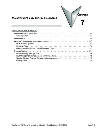
TC 9-524The jaws are moved simultaneously within the chuck by ascroll or spiral-threaded plate. The jaws are threaded to thescroll and move an equal distance inward or outward as thescroll is rotated by the adjusting pinion. Since the jaws areindividually aligned on the scroll, the jaws cannot usually bereversed. Some manufactures supply two sets of jaws, one forinternal work and one for external work. Other manufacturesmake the jaws in two pieces so the outside, or gripping surfacemay be reversed. which can be interchanged.The independent chuck, Figure 7-19, generally has four jawswhich are adjusted individually on the chuck face by means ofadjusting screws. The chuck face is scribed with concentriccircles which are used for rough alignment of the jaws whenchucking round workplaces. The final adjustment is made byturning the workpiece slowly by hand and using a dialindicator to determine it’s concentricity. The jaws are thenreadjusted as necessary to align the workpiece within thedesired tolerances.The universal scroll chuck can be used to hold andautomatically center round or hexagonal workplaces. Havingonly three jaws, the chuck cannot be used effectively to holdsquare, octagonal, or irregular shapes.The jaws of the independent chuck may be used asillustrated or may be reversed so that the steps face in theopposite direction; thus workplaces can be gripped eitherexternally or internally. The independent chuck can be used tohold square, round, octagonal, or irregularly shapedworkplaces in either a concentric or eccentric position due tothe independent operation of each jaw.Because of its versatility and capacity for fine adjustment,the independent chuck is commonly used for mounting oddshaped workplaces which must be held with extremeaccuracy.A combination chuck combines the features of theindependent chuck and the universal scroll chuck and canhave either three or four jaws. The jaws can be moved inunison on a scroll for automatic centering or can be movedindividually if desired by separate adjusting screws.The drill chuck, Figure 7-19, is a small universal chuckwhich can be used in either the headstock spindle or thetailstock for holding straight-shank drills, reamers, taps, orsmall diameter workplaces. The drill chuck has three or fourhardened steel jaws which are moved together or apart byadjusting a tapered sleeve within which they are contained.The drill chuck is capable of centering tools and smalldiameter workplaces to within 0.002 or 0.003 inch whenfirmly tightened.The collet chuck is the most accurate means of holding smallworkplaces in the lathe. The collet chuck consists of a springmachine collet (Figure 7-20) and a collet attachment whichsecures and regulates the collet on the headstock spindle of thelathe.The spring machine collet is a thin metal bushing with anaccurately machined bore and a tapered exterior. The collethas three lengthwise slots to permit its sides being sprungslightly inward to grip the workpiece. To grip the workpieceaccurately, the collet must be no more than 0.005 inch largeror smaller than the diameter of the piece to be chucked. Forthis reason, spring machine collets are available in incrementsof 1/64 inch. For general purposes, the spring machine colletsare limited in capacity to 1 1/8 inch in diameter.7-12
TC 9-524THE COLLET CHUCK IS THE MOST ACCURATE MEANS OF HOLDING SMALLWORKPIECES IN THE LATHE7-13
TC 9-524For general purposes, the spring machine collets are limitedin capacity to 1 1/8 inch in diameter.steel boxes designed for holding the collets. Collets arenormally stored in steel boxes designed for holding the collets.The collet attachment consists of a collet sleeve, a drawbar,and a handwheel or hand lever to move the drawbar. Thespring machine collet and collet attachment together form thecollet chuck. Figure 7-20 illustrates a typical collet chuckinstallation. The collet sleeve is fitted to the right end of theheadstock spindle. The drawbar passes through the headstockspindle and is threaded to the spring machine collet. When thedrawbar is rotated by means of the hand wheel, it draws thecollet into the tapered adapter, causing the collet to tighten onthe workpiece. Spring machine collets are available indifferent shapes to chuck square and hexagonal workplaces ofsmall dimensions as well as round workplaces.The Jacob’s spindle-nose collet chuck (Figure 7-21) is aspecial chuck is used for the J
with the lathe and its operations to accomplish the repair and fabrication of needed parts. TYPES OF LATHES lathe (Figure 7-1 ) is ideally suited for this purpose. A trained Lathes can be divided into three types for easy identification:operator can accomplish more machining jobs with the