Transcription
White PaperCisco Configuration Professionalfor Catalyst (CCP-CATALYST) 2018 Cisco and/or its affiliates. All rights reserved. This document is Cisco Public Information.Page 1 of 30
Abstract This document describes the benefits of Cisco Configuration Professional for Catalyst and how it can be used tomanage a stack or cluster of Cisco Catalyst switches with a simple and intuitive GUI hosted on the switch itself.In addition, this document covers how Cisco Configuration Professional for Catalyst enables the onboarding andmonitoring of Cisco Catalyst switches after they are unpacked from the box to exploit the power of Cisco Catalystand Cisco IOS Software while managing your network. 2018 Cisco and/or its affiliates. All rights reserved. This document is Cisco Public Information.Page 2 of 30
Contents1. Introduction . 52. List of supported browsers . 53. List of supported switches . 54. Where to download the Cisco Configuration Professional software . 55. Installing new switches with Cisco Configuration Professional . 65.1 Steps to perform on a switch factory-shipped with Cisco Configuration Professional . 65.1.1 Before the installation procedure . 65.2 Switch installation steps . 65.2.1 Basic configuration. 65.2.2 Interface configuration . 75.2.3 Layer 3 configuration . 75.2.4 Advanced configuration . 85.2.5 Summary page. 86. Installing Cisco Configuration Professional on existing switches. 96.1 Steps to install CCP-C.tar . 96.2 Steps to install Cisco IOS Software (.tar image) . 107. Introduction to the user interface . 107.1 Monitoring dashboard . 108. Configuring switch system settings . 128.1 Set clock . 128.1.1 Set system clock during initial setup . 128.1.2 Set system clock later with Cisco Configuration Professional . 138.2 Basic switch configuration . 149. Connect via Bluetooth . 149.1 Steps to connect to the switch via Bluetooth . 1410. Connecting uplinks. 1610.1 Standalone uplink interface . 1610.2 Bundled uplink interfaces (LAG) . 1711. Managing endpoint devices . 1711.1 Monitoring endpoint devices (clients) . 1711.2 Configurations for endpoints . 1811.2.1 Monitoring PoE clients . 1811.2.2 Configuring data and voice VLANs for clients . 1811.2.3 Ports as trunks . 1911.2.4 Bundle multiple access ports as LAG (EtherChannel) . 1911.2.5 Speed up client connections (portfast) . 2012. Administrative workflows . 2012.1 Gain visibility into the traffic pattern passing through the switch or switch stack . 2012.2 Secure the network by protecting the switch against vulnerabilities . 2112.3 Conserve operational expenses through energy saver . 2412.4 Add a static route . 2512.5 Replace a faulty switch with a new switch. 2612.5.1 Upgrade Cisco IOS on the new switch to match the old switch . 2612.5.2 Replace the configuration on the new switch . 2612.6 Erase switch configuration . 2713. Tools . 2713.1 Validate reachability within the network . 27 2018 Cisco and/or its affiliates. All rights reserved. This document is Cisco Public Information.Page 3 of 30
13.2 Know your switch health . 2713.3 Getting technical support . 2813.4 Choose your language settings . 2913.5 Using the CLI . 30 2018 Cisco and/or its affiliates. All rights reserved. This document is Cisco Public Information.Page 4 of 30
1. IntroductionCisco Configuration Professional for Catalyst is software that provides users an easy-to-use and intuitive graphicalinterface to configure, manage, and monitor a standalone, stack, or cluster of Cisco Catalyst switches. It isindependent of the Cisco IOS Software version on the switch.Note:This white paper is based on Cisco Configuration Professional release 01.04.002. List of supported browsers Mozilla Firefox 48 or later Microsoft Internet Explorer 11 or later Apple Safari 9 or later Google Chrome 52 or later3. List of supported switches Cisco Catalyst 2960-X Series Switches Cisco Catalyst 2960-XR Series Switches Cisco Catalyst 2960-L Series Switches Cisco Catalyst 2960-Plus Series Switches Cisco Catalyst 2960-CX Series Switches Cisco Catalyst 3560-CX Series Switches Cisco Catalyst Digital Building Series Switches4. Where to download the Cisco Configuration Professional softwareThe Cisco Configuration Professional for Catalyst software is available as an independent software (.tar file)downloadable from the https://www.cisco.com/go/ccp-catalyst website.When customers deploy newer versions of Cisco IOS Software (15.2(5)E or later), Cisco ConfigurationProfessional is bundled with the Cisco IOS image (.tar file).On newer switches, such as the 2960-L and Digital Building Series, Cisco Configuration Professional is preloadedon the switch at manufacturing and can be used to onboard the switch to the network out of the box without aconsole connection. Table 1 lists the Cisco IOS Software versions for supported by the various Cisco Catalystswitch series.Table 1.Supported Cisco IOS versions for different Cisco Catalyst switchesSwitch seriesCisco IOS 5)E1Digital Building15.2(5)EX 2018 Cisco and/or its affiliates. All rights reserved. This document is Cisco Public Information.Page 5 of 30
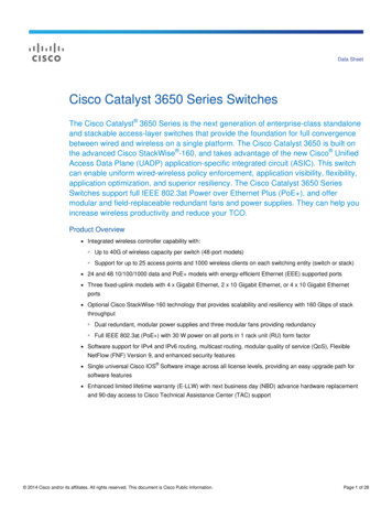
5. Installing new switches with Cisco Configuration ProfessionalFor those switches that are factory-shipped with Cisco Configuration Professional, users can initiate switchinstallation (day-0 setup) with a PC or tablet browser.There are two ways of connecting to the switch (Figure 1):1.Using an Ethernet cable to connect a computer to any Ethernet port of the switch2.Bluetooth pairing between a computer or tablet and a Bluetooth USB dongle attached to the switchFigure 1.Connecting a new switch to a laptop, PC, or tablet5.1 Steps to perform on a switch factory-shipped with Cisco Configuration Professional5.1.1 Before the installation procedure1.Power up the switch and launch the switch to day0 mode following the instructions.2.Connect to the switch over any Ethernet port. Set the NIC to accept a DHCP IP address.3.The switch acts as a DHCP server and assigns the connected PC an IP address from a predefined IP pool(10.0.0.0 /24).4.The switch by default has an IP address of 10.0.0.1. The UI can be accessed on the browser with the IPaddress 10.0.0.1. Default username/password: cisco/cisco.5.2 Switch installation steps5.2.1 Basic configurationThis step allows users to configure the switch with parameters to identify a switch and minimum mandatory securityparameters. 2018 Cisco and/or its affiliates. All rights reserved. This document is Cisco Public Information.Page 6 of 30
5.2.2 Interface configurationThis steps allows users to configure the segmentation parameters and also define the interfaces that will beconnected to end-user devices as well as the interface that will connect to the existing network.5.2.3 Layer 3 configurationThis step allows users to configure the IP address of the switch interfaces that may be used to access the switch orthat will serve as a gateway for end devices connected to the switch. 2018 Cisco and/or its affiliates. All rights reserved. This document is Cisco Public Information.Page 7 of 30
5.2.4 Advanced configurationThis step allows users to enable protocols that will enable access to the switch for configuration once installed onthe network.5.2.5 Summary pageThis page allows users to review the configuration options selected in the previous four steps. 2018 Cisco and/or its affiliates. All rights reserved. This document is Cisco Public Information.Page 8 of 30
Once the configuration is submitted, the IP address assigned to the switch changes to the IP address configuredon the Layer 3 Configuration screen (section 3.2.3).The user interface will be redirected to this new IP address.6. Installing Cisco Configuration Professional on existing switchesThis section describes how to use Cisco Configuration Professional on supported switches in existingdeployments. This is for switches that were not factory-shipped with Cisco Configuration Professional or cannot beupgraded to the Cisco IOS Software version that is bundled with Cisco Configuration Professional.Note: Cisco Configuration Professional for Catalyst is independent of the switch Cisco IOS Software.There are two options for installing Cisco Configuration Professional:1.Download only Cisco Configuration Professional and use the existing Cisco IOS Software (download only theCCP-C.tar).2.Download a Cisco IOS bundle file that contains Cisco Configuration Professional and a newer version ofCisco IOS.6.1 Steps to install CCP-C.tar1.Browse to https://www.cisco.com/go/ccp-catalyst and download the CCP.tar image for the switch.2.Download the CCP-CATALYST file to the switch flash.3.Create a directory on the flash:mkdir flash:CCP-CATALYST4.Expand the .tar file in the flash:archive tar /xtract flash:/c2960l-cwml.tar flash:/CCP-CATALYST 2018 Cisco and/or its affiliates. All rights reserved. This document is Cisco Public Information.Page 9 of 30
5.Configure the switch parameters.6.Point the switch to the CCP-CATALYST files:ip http path flash:CCP-CATALYST7.8.Specify authentication parameters:a.ip http authentication enableb.ip http authentication aaa/localEnable the switch to act as the HTTP server:a.ip http serverAccess Cisco Configuration Professional from the web browser by using the IP address configured on the switch.The username and password will be as configured on the switch locally or using AAA.6.2 Steps to install Cisco IOS Software (.tar image)The procedure is the same as the Cisco IOS upgrade procedure on a switch with a .tar image.7. Introduction to the user interface7.1 Monitoring dashboardThe dashboard provides a single-pane view of the switch. The user can monitor the connected and error ports, thehealth of the switch, Power over Ethernet (PoE) available, critical alerts on the switch, etc.This is a single-pane view of the switch, and it provides the following details:1.Switch details: Hardware type of the switch and the Cisco IOS Software version currently running on it.2.Language support: The user interface can be converted to easily support other languages.Current language support: English (default), Mandarin, Japanese, and Korean 2018 Cisco and/or its affiliates. All rights reserved. This document is Cisco Public Information.Page 10 of 30
3.Icons:Opens a guide to explain the features being configured on the switch.Displays the version of Cisco Configuration Professional running on the switch.Displays the latest system logs from the switch.Clicking this icon will save the current configuration of the switch to the startup configuration.Clicking this icon brings up the Command-Line Interface (CLI).4.Switch view: Dynamic display of switch ports and their status for each switch, along with display of itshostname, serial number, and MAC address. In the case of a stack, details about the role of each switch, suchas primary or stack member details, are displayed.5.System messages: Displays the critical switch logs. Only the Critical, Alerts, and Emergency logs aredisplayed here.The logs are color-coded to show the level of the log.The logs can be exported to an Excel spreadsheet for troubleshooting or attaching to a Cisco TechnicalAssistance Center (TAC) case.6.Navigation pane: The pane is a tree design with two levels of branching.The first level has Monitoring, Configuration, Services, General Settings, and Help. MonitoringDashboard: A single-page view of the switch health.Ports: Displays all the port statistics. The error counters on the individual and bundled ports are displayedon this page.Clients: Gives a snapshot view of the end devices connected to the switch and also provides detailssuch as: Switch port to end device mapping Device type (router, switch, IP phone, Windows PC, etc.) VLAN of the end device MAC address of the end device IP address of the end device Power drawn by the end device Operating system of the end deviceThis list can be exported as a spreadsheet and saved for auditing purposes. ConfigurationSwitch: General and basic switch configurations can be done on this page (such as setting the hostname,switch IP address, Maximum Transmission Unit [MTU], etc.) Other switch-level settings such as physicalstacking, virtual stacking parameters, spanning tree, VLAN Trunking Protocol, and Bluetooth can beconfigured here.Ports: Port parameters such as VLAN association, DHCP Snooping, quality of service, and storm controlparameters can be configured on this page. 2018 Cisco and/or its affiliates. All rights reserved. This document is Cisco Public Information.Page 11 of 30
Troubleshooting: Basic troubleshooting, such as connectivity of devices from the switch, can be performedby using ping or traceroute. Device health checks can be performed by running diagnostics. The user canalso erase switch configurations or reload the switch stack or individual switch.VLAN: Configuration related to VLAN, such as creation of Layer 2 VLAN and Switch Virtual Interface (SVI),as well as setting up IP DHCP Snooping on a list of VLANs in order to secure the network, can be done onthis page. ServicesNetFlow: Allows configuration of the switch to export details of the packets sent to the switch on differentports.Static routing: Through this page, users can create new static routes or modify or delete existing routes onsupported platforms.Security: Users can set up comprehensive security on the switch through this pane by configuring portbased Authentication, Authorization, and Accounting (AAA) using either RADIUS, TACACS , or LightweightDirectory Access Protocol (LDAP) along with support for multiple access policies such as IEEE 802.1X,MAC Authentication Bypass (MAB), and WebAuth.ACL: Access control lists can be configured through this page, allowing the administrator to limit networktraffic and restrict network access to certain users and devices.Energy Saver: Using this service, user can harness the potential of Cisco EnergyWise and Energy-EfficientEthernet (EEE) to decrease energy consumed by the switch and endpoints connected to the switch bysetting different power levels and using the Cisco EnergyWise Wake on LAN feature. General SettingsManagement: HTTP and SNMP parameters can be configured on this page.Software update: Provides administrators an option to upgrade the Cisco Configuration Professional versionor the switch Cisco IOS version remotely through the local system.System: Various time-related settings, such as setting the time zone and adding a Network Time Protocol(NTP) server can be done through this page. Administrators can also create Dynamic Host ConfigurationProtocol (DHCP) scopes and transfer a configuration file to or from the switch into a Trivial FTP (TFTP)server or local system.User Administration: Allows administrators to control access to the switch by setting up new users and theirprivilege levels, modifying the password or privilege level of existing users, and deleting users altogether.7.Switch information: Dashlets displaying critical real-time system information such as CPU and memoryutilization, system temperature and power consumption. The dashboard is refreshed every 60 seconds withupdated data.8. Configuring switch system settings8.1 Set clock8.1.1 Set system clock during initial setupDuring the initial setup of switches shipped with Cisco Configuration Professional, the date and time is populatedautomatically from the clock on the user’s laptop. They can also be set manually. 2018 Cisco and/or its affiliates. All rights reserved. This document is Cisco Public Information.Page 12 of 30
8.1.2 Set system clock later with Cisco Configuration ProfessionalConfigure clock to synchronize with NTP serverA user can synchronize the switch clock by configuring an NTP server underGeneral Settings System Time. Once an NTP server is added, the user can check the synchronization statuson the same page.Configure clock manuallyA user can also set the system time manually on the switch, along with advanced options such as setting the timezone and enabling daylight savings. These settings can be found under General Settings System Time. 2018 Cisco and/or its affiliates. All rights reserved. This document is Cisco Public Information.Page 13 of 30
8.2 Basic switch configurationBasic attributes of the switch, such as the hostname, default gateway or route, system MTU, and switchmanagement IP address can be configured on this page.Note:Hovering over the “?” explains the fields in detail. The input ranges are also explained.9. Connect via Bluetooth9.1 Steps to connect to the switch via BluetoothOver-the-air access to the web UI and CLI through Telnet and SSH is available for switches that support anexternal Bluetooth dongle that plugs into the USB port, providing easy access to the switch. Cisco ConfigurationProfessional provides an easy way to configure the switch for Bluetooth under Configuration Switch Bluetooth: Connect a Bluetooth dongle to the USB port on the switch (USB 2.0 with Bluetooth version 4.1). Once the dongle is connected, toggle Bluetooth to On. Assign an IP address to the Bluetooth interface. Create a DHCP pool for the Bluetooth PAN devices in the same subnet as the Bluetooth interface. Scan for Bluetooth devices from the laptop. 2018 Cisco and/or its affiliates. All rights reserved. This document is Cisco Public Information.Page 14 of 30
Note:The dongle name shows up with the last four characters of the MAC address.cisco#show bluetooth statsBT Interface is ReadyBT Dongle Present: YesBT Stack Enabled: YesBT Stack Ready: YesAttached BT dongle mac: 00:1A:7D:DA:xx:xxOnce the device is connected via Bluetooth, you will see the following:cisco#show ip interface brief Bluetooth0InterfaceIP-AddressOK? Method StatusBluetooth0172.16.0.1YES NVRAM ProtocolupYou will now be able to access the user interface of the switch by typing the IP address of the Bluetoothinterface in the browser. 2018 Cisco and/or its affiliates. All rights reserved. This document is Cisco Public Information.Page 15 of 30
10. Connecting uplinksThe switches connect to other network devices on ports marked “Uplink Ports.” These are highlighted in the figurebelow.The color of a port indicates its status.Gray: Port is “down.”Green: Port is “up.”Red: Port is in “error” condition.The uplink can be a single port (standalone interface) or can be multiple ports bundled together (Link AggregationGroup [LAG] interface or EtherChannel).An uplinks can be configured as a trunk interface (Layer 2 port) or can be assigned an IP address (Layer 3 port).10.1 Standalone uplink interfaceA single trunk port can be configured by selecting the appropriate port from the port view under Configuration Ports, which allows configuration to be set all the way from adding a description to configuring Auto QoS. A usercan also easily configure the port as a routed port by toggling the port mode.On the same page, Cisco Configuration Professional allows users to configure multiple ports at once.To configure multiple ports at once, select multiple ports in the switch view (to select multiple ports in Windows,Ctrl-click; on a Mac, Command-click).Note:When multiple interfaces are selected, the old port configurations of the individual ports are erased. 2018 Cisco and/or its affiliates. All rights reserved. This document is Cisco Public Information.Page 16 of 30
10.2 Bundled uplink interfaces (LAG)Multiple ports can be selected and bundled to act as one port.After selecting the interfaces to bundle, select the protocol to bundle: Link Aggregation Control Protocol (LACP),Port Aggregation Protocol (PAgP), or ON.Also enable or disable the keep-alive, based on whether the aggregation method needs to be active/passive orDesirable/Auto.Once the port channel is configured and the ports are bundled in the port channel, the port statistics of the portchannel can be viewed on the Monitoring dashboard under Monitoring Ports.11. Managing endpoint devices11.1 Monitoring endpoint devices (clients)Clients can be connected to the physical ports on the switch. 2018 Cisco and/or its affiliates. All rights reserved. This document is Cisco Public Information.Page 17 of 30
The type of end clients connected and their details, such as their MAC address, IP address, VLAN associated, andpower drawn from the switch can be viewed on the Clients page under Monitoring Clients. This list can also beexported to a spreadsheet for easy documentation.11.2 Configurations for endpointsDifferent kinds of end clients can connect to the switch, such as IP phones, PCs, cameras, access points, VMservers, printers, point-of-sale devices, etc. Cisco Configuration Professional provides ways to easily monitor andmanage clients connected.11.2.1 Monitoring PoE clientsIf the end client is drawing power from the switch to boot up, the port clearly indicates the amount of power beingdrawn. To see this, hover over the port in the switch view of the Monitoring dashboard under Monitoring Ports.11.2.2 Configuring data and voice VLANs for clientsWhen PCs and laptops are connected to the IP phone port, which in turn is connected to the switch port, it is bestpractice is to segregate the voice traffic from the IP phone and the data traffic from the PC. Configure the port tosend phone traffic on a voice VLAN and traffic from PCs on the data VLAN.Click on the port that needs to be configured in the switch view.Note:Multiple ports can be selected to apply configurations at the same time (on a Windows PC, Ctrl-click; on aMac, Command-click). Any preexisting configurations on the ports selected will be erased. 2018 Cisco and/or its affiliates. All rights reserved. This document is Cisco Public Information.Page 18 of 30
11.2.3 Ports as trunksWhen connecting VM server ports or access points that carry WLAN traffic to the switch, the switch port will needto be configured as a trunk.Click on the port that needs to be configured.Filter the VLANs allowed on the trunk by selecting the VLAN IDs and listing the VLANs under the VLAN IDs,separated by commas (,) or hyphens (-).Note:Multiple ports can be selected to apply configurations at the same time (on a Windows PC, Ctrl-click, on aMac, Command-click). The preexisting configurations on the ports selected will be rewritten to defaultconfigurations.11.2.4 Bundle multiple access ports as LAG (EtherChannel)When connecting multiple ports of a switch to multiple ports on the end client, such as servers or hubs, to getbetter throughput multiple interfaces can be selected and configured in a bundle. (To select multiple interfaces onWindows, Ctrl-click; on a Mac, Command-click.)Note:When multiple interfaces are selected, the original configurations on the interfaces are erased. 2018 Cisco and/or its affiliates. All rights reserved. This document is Cisco Public Information.Page 19 of 30
11.2.5 Speed up client connections (portfast)Ports connecting to phones, lights, etc. sometimes need to be transitioned from listening to a forwarding state ingroups of 5 instead of in groups of 60.12. Administrative workflows12.1 Gain visibility into the traffic pattern passing through the switch or switch stackNetFlow can be configured on the switch to export details of the packets forwarded to and from the switch in orderto gain visibility into the network.NetFlow can now be configured with Cisco Configuration Professional with just a few clicks underServices NetFlow. Templates are used to configure NetFlow, thus eliminating the need to understand acomplicated set of commands.The 2960-X and 2960-XR Series support full NetFlow from Cisco IOS 15.2(5)b onward with minimal impact onperformance. (Check the configuration guide for the switch model to confirm that it supports NetFlow.)Choose the template and sampling method based on the reason for enabling NetFlow. Full, Random, andDeterministic sampling methods are supported.Configure the IP address of the collector (using software such as Lancope or Cisco Stealthwatch that displays theinformation collected and exported by the switch in a human-readable form).Apply the configured parameters to the switch interface (VLAN, port etc.). 2018 Cisco and/or its affiliates. All rights reserved. This document is Cisco Public Information.Page 20 of 30
Note:Refer to the switch configuration guide to understand NetFlow in detail.All the interfaces (VLAN
Note: Cisco Configuration Professional for Catalyst is independent of the switch Cisco IOS Software. There are two options for installing Cisco Configuration Professional: 1. Download only Cisco Configuration Professional and use the existing Cisco IOS Software (download only the CCP-C.tar). 2. Download a Cisco IOS bundle file that contains .