Transcription
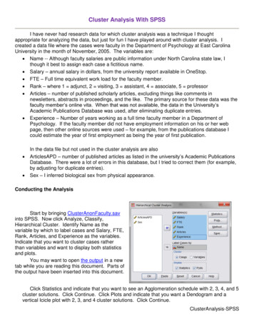
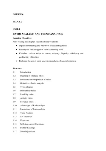
DESIGN & ANALYSIS OF MULTISTOREY (G 3) RESIDENTIALBUILDING USING STAAD.PRO & AUTOCADArjun Sahu[1] , Anurag Verma[2] , Ankit Singh[3] , Aryan Pal[4] , Mohd. Shariq[5]1.Student, B.Tech Final Year, 2.Student,B.Tech Final Year, 3.Student,B.Tech Final Year4.Student, B.Tech Final Year, 5.Assistant ProfessorDepartment Of Civil EngineeringAxis Institute of Technology and Management ,Kanpur, Indiahas become the drawing and detailing works were done by creating useof Auto CAD 2014.ABSTRACT- In order to compete in the ever growing competentmarket it is very important for a structural engineer to save time. As asequel to this an attempt is made to analyze and design a multistoriedbuilding by using a software package staad pro.For analyzing a multi storied building one has to consider all thepossible loadings and see that the structure is safe against all possibleloading conditions.There are several methods for analysis of different frameslike kani’s method, cantilever method, portal method, and Matrixmethod.The present project deals with the design & analysis of amulti storied residential building of G 3 consisting of 2 apartments ineach floor. The dead load &live loads are applied and the design forbeams, columns, footing is obtainedSTAAD Pro with its new features surpassed itspredecessors and compotators with its data sharing capabilities withother major software like AutoCAD.We conclude that staad pro is a very powerful tool which can savemuch time and is very accurate in Designs.Thus it is concluded that staad pro package is suitable for the designof a multistoried building.Key words: STAAD.Pro, Multi-storey building,Autocad,Concrete mix, Steel strength, Limit state method.2.2 STAAD.PROSTAAD.Pro is a user-friendly software which is used for analysingand designing of structure by the structural engineers. STAAD Proprovides a lot of precise and correct results than manual techniques.It’s the foremost computer code for 3D model generation and multimaterial design. The software is fully compatible with all windowsoperating system but is optimized for windows XP. STAAD.Prosoftware is used for static or dynamic analysis for structures such asbridges, low rise or high-rise buildings, stadiums, steel structures, etc.First step in STAAD.Pro is to specify the geometry of the structureand then the properties of the members are mentioned. Then thesupports are generated and loadings are specified on the structure.Finally, the structure is analysed.3. BUILDING PLANNING3.1GROUND FLOOR1. INTRODUCTIONIn every aspect of human civilization, we needed structures to live.The structures should be built in an efficient manner so that it canserve people and save money. In simple words, the building means anempty surrounded by walls and roofs, in order to give shelter forhuman beings. In early times humans have lived in caves to protectthemselves from wild animals, rain etc. Then, humans developed andbuilt their homes using timbers and lived. Nowadays the recent homesare developed into individual and multi-storey buildings. Buildings arethe necessary indicator of social progress of the county. At currentsituation, many new techniques have been developed for constructions.So, that the buildings are built economically and quickly to fulfil theneeds of the people. A building frame is a three-dimensional structurewhich consists of column, beams and slabs. Because of growingpopulation, high rise buildings are coming into demand. Buildingsconstitute a part of the definition of civilizations, a way of lifeadvanced by the people. The buildings should be constructed forhuman requirements and not for earning money. Buildings are built indifferent sizes, shapes and functions.Fig.1 plan of ground floor3.2 FIRST, SECOND AND THIRD FLOOR2. A BRIEF DESCRIPTION OFSOFTWARE USED Auto CAD STAAD.Pro 2.1 Auto CADAuto Cad is a designing and drafting software which is used fordeveloping 2-dimensional and 3-dimensional structures, developedand sold by Autodesk, Inc. It is a vector graphics drawing programme.It uses primitive entities- comparable to lines, polylines, circles, arcsand text as the foundation for the complex. Auto CAD’s native fileformat, DWG, and to a lesser extent, its interchange file format, DXFFig.11 plan of first, second and third floor4. LITERATURE REVIEW1
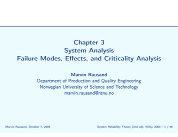
Sreeshna K.S (2016) this paper deals with structural analysis anddesign of B G 4 storied apartment building. The work was completedin three stages. The first stage was modelling and analysis of buildingand the second stage was to design the structural elements and thefinal was to detail the structural elements. In this project STAAD.Prosoftware is used for analysing the building. The IS:875 (Part 1) and(Part 2) were referred for dead load and live load. Design of structuralelements like beam, column, slab, staircase, shear wall, retaining wall,pile foundation is done according to IS Codes.Amar Hugar et al., (2016) has been discussed that the ComputerAided Design of Residential Building involves scrutiny of buildingusing STAAD.Pro and a physical design of the structure. Traditionalway of study shows tedious calculations and such tests is a timeconsuming task. Analysis are made quickly by using software’s. Thisproject completely deals with scrutiny of the building using thesoftware STAAD.Pro. Finally, the results are compared with physicalcalculations. The elements are created as per IS:456-2000.Bandipati Anup et al., (2016) this paper deals with evaluate andplan a multi-storeyed building [G 2 (3- dimensional frame)]adopting STAAD Pro. The technique used in STAAD.Pro is limitstate technique. Initially they have created 2-D frames and crosschecked with physical calculations. The exact result should be proved.We tested and created a G 2 storey building [2-D Frame] instantlyfor all feasible load combinations. The work has been finished withsome more multi-storeyed 2-Dimensional and 3- Dimensional framesbeneath various load combinationsAman et al., (2016) has discussed that the point of the structuralengineer is to model a guarded structure. Then the structure issubjected to various types of loading. Mostly the loads put in on thebuilding are considered as static. Finite part analysis that exhibit theresult of dynamic load like wind result, earthquake result, etc. Thework is conducted using STAAD.Pro software.Madhurivassavai et al., (2016) he says that the most commonproblem country facing is the growing population. Because of the lessavailability of land, multi-storey building can be constructed to servemany people in limited area. Efficient modelling is performed usingSTAAD.Pro and AutoCAD. Manual International Journal of Pure andApplied Mathematics Special Issue 2798 calculations for more thanfour floor buildings are tedious and time consuming. STAAD.Proprovides us a quick, efficient and correct platform for analysing andcoming up with structuresBorugadda Raju et al., (2015) has been designed and analysedG 30 multi-storey building adopting STAAD.Pro in limit statemethodology. STAAD.Pro contains an easy interface that permits theusers to produce the mount and the load values and dimensions areinputted. The members are designed with reinforcement details forRCC frames. The analysis is completed for two dimensional framesand then it is done for more multi-storeyed 2-D and 3-D frames undervarious load combinations.Anoop. A, (2016) has explained that the scope of the project is toprovide a multi storied building of G 5 floors. Revit 2011 and AutoCAD 2014 software is used for developing 3-D models. The structureanalysis and design are done using STAAD.Pro. The results arechecked for selected members using limit state method of design asper IS 456-2000.Nasreen. M. Khan (2016) has mentioned that logical data isincredibly necessary and essential talent required by each and everyengineer. The project encompasses a shear wall round the elevator pit.During this project the structure is meant and tested with the help ofSTAAD.Pro and the scheming was done physically. Layout of beam,column, slab, shear wall, stair case, shear wall, tank and an isolatedfooting are done. Finally, the detailing was done using AutoCADR.D. Deshpande et al., (2017) has said that the structural analysismay be a branch that involves resolution of working on construction,so asto forecast the reply of real construction such as buildings,bridges, trusses etc. This project makes an attempt to view theconstruction working of varied elements inthe multi-storied building.Analysis, scheming and evaluation of multi-storied building has beenobsessed for Basement G 2 Building. According to materialproperties the dead load is calculated, live loads is taken from codeIS875-part 2 and piles are schemed based on protected bearingcapacity of soil. For the design of columns and beams limit statemethod is used.SK Saleem (2017) has explained that the objective of the project is todetect and scan a multi-storey building. Load calculations are donemanually and STAAD.Pro software is used for analysing the structure.STAAD.Pro is the recommended software. STAAD.Pro is userfriendly software which allows the users to make the mount and theload values to be given and dimensions. Then the work is continuedfor 2-D and 3-D frames with different loading conditions.Deevi Krishna Chaitanya (2017) has said that in order to compete inthe ever-growing competent market it is very important for a structuralengineer to save lots of time. For this an attempt is made to model andsurvey a construction using software. For analysing the structure allpossible loads are considered to see whether the structure is safeagainst loading. There are many strategies for analysis of variousframes like kani’s methodology, cantilever methodology, portalmethodology and Matrix methodology. The dead load &live loads areapplied. Then, the design for beams, columns, footing are done.STAAD.Pro is a very powerful toll which can save time.K. Rama Raju et al., (2013) has explained that the building becomestaller, the quantity of structural material needed to withstand theoblique loads rises extremely. Tall buildings design involvesconceptual design, preliminary design and lateral loads. Criteria fordesign are strength and serviceability. Protection ofthe structure isexamined against permissible limits, roof displacements, etc.5. TYPES OF LOADS USEDThe loads which are considered for analysis are, Dead loads Live loads Earthquake load 5.1 DEAD LOADAll permanent loads in the building are considered as dead loads. Thedead loads comprise of self-weight of the building, weight of wall,weight of slab, floor finish and permanent materials placed on thebuilding. Dead loads are specified in IS 875 (Part 1).5.1.1 SELF WEIGHTIn load case we have option called self weight which automaticallycalculates weights using the properties of material i.e., density andafter assignment of dead load the skeletal structure looks red in coloras shown in the figure.Fig.3 Self weight show red color;5.1.2 Wall load external wallOuter wall load wall thickness X height X density 0.23 X 3 X 20Outer wall load 13.8kn/mOuter wall load shown given below figure in blue color2
Fig8 floor loadFig.4 outer wall load5.1.3 Internal wall load (partition wall)5.4 Earthquake loadInternal wall load 13.9/2(thickness of partition wall half of the outerwall)Internal wall load 6.9 kN/mWe are taken earthquake load as per IS code 1893-20005.4.1 Earthquake load in x-directionFig.9 earthquake load in x-directionFig.5 internal wall load shown blue color5.4.21 Earthquake load in z-direction5.1.4Parapet loadTake, thickness of parapet 0.115mHeight of parapet 1mParapet load 0.115X1X20Parapet load 2.3kN/mFig.10 earthquake load in z-direction5.5 LOAD COMBINATIONSThe different combinations used in the project are1.5(D.L L.L.)1.2(D.L L.L)1.2(D.L L.L EQX)1.2(D.L L.L EQZ)1.2(D.L L.L)-1.2EQX1.2(D.L L.L)-1.2EQZ1.5D.L1.5(D.L EQX)1.5(D.L EQZ)1.5D.L-1.5EQX1.5D.L-1.5EQZ0.9D.L 1.5EQX0.9D.L 1.5EQZ0.9D.L-1.5EQX0.9D.L-1.5EQZFig.6 parapet load shown blue color5.2 Live Loads:We are taken in live load is floor loadFloor load Thickness X densityFloor load 0.156X25Floor load 0.0039N/mmFig.7 Floor load5.3 Floor loadFloor load is calculated based on the load on the slabs. Assignmentof floor load is done by creating a load case for floor load. After theassignment of floor load our structure looks as shown in the belowfigure.The intensity of the floor load taken is: 0.0015N/mm2Fig.11 3-D view of the model3
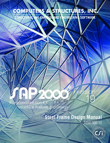
M25Fe415 (Main)Fe415 (Sec.)LENGTH: 1750.0 mm SIZE: 350.0 mm X 350.0 mmCOVER: 30.0 mmSUMMARY OF REINF. AREA --------------------------------SECTION 0.0 mm 437.5 mm 875.0 mm 1312.5 mm1750.0 25.81225.81REINF.(Sq. mm) (Sq. mm) (Sq. mm) (Sq. mm) Sq. mm) (Sq. mm) (Sq. mm) (Sq. mm) ---------------------------------Fig.12 3-D Rendered view of the modelSUMMARY OF PROVIDED REINF. -----------------------------SECTION 0.0 mm 437.5 mm 875.0 mm 1312.5 mm1750.0 16í3-16íREINF. 1 layer(s) 1 layer(s) 1 layer(s) 1 layer(s) 1 layer(s)BOTTOM 10-10í7-10íREINF. 2 layer(s) 1 layer(s)Fig.12 3-D Rendered view of the model5-10í1 layer(s)3-10í1 layer(s)4-10í1 layer(s)SHEAR 2 legged 8í 2 legged 8í 2 legged 8í 2 legged 8í 2legged 8íREINF. @ 145 mm c/c @ 145 mm c/c @ 145 mm c/c @ 145 mmc/c @ 145 mm ----------------------------SHEAR DESIGN RESULTS AT DISTANCE d (EFFECTIVEDEPTH) FROM FACE OF THE ---------------------------------SHEAR DESIGN RESULTS AT 537.0 mm AWAY FROMSTART SUPPORTVY 97.01 MX 0.52 LD 16Provide 2 Legged 8í @ 145 mm c/c Fig.13 Showing Shear Force of all the beams6.2 Column design (Column no.326) C O L U M N N O. 326 D E S I G N R E S U L T SM25Fe415 (Main)LENGTH: 3000.0 mmFig.14 showing bending moments of all the beamsFe415 (Sec.)CROSS SECTION: 450.0 mm X 350.0mm COVER: 40.0 mm** GUIDING LOAD CASE:1 END JOINT:150 TENSIONCOLUMNREQD. STEEL AREA : 1260.00 Sq.mm.REQD. CONCRETE AREA: 156240.00 Sq.mm.MAIN REINFORCEMENT: Provide 12 - 12 dia. (0.86%, 1357.17Sq.mm.)(Equally distributed)TIE REINFORCEMENT: Provide 8 mm dia. rectangular ties @ 190Fig.15 showing the max absolute of plates6. STRUCTRE DESIGN6.1 Beam design (Beam no.196)mm c/cSECTION B E A M N O. 196 D E S I G N R E S U L T SCAPACITYREQUIRED (KNS-MET)4BASEDONREINFORCEMENT
-------Puz : 2149.88 Muz1 : 63.18 Muy1 : ------------WORST LOAD CASE:INTERACTION RATIO: 0.15 (as per Cl. 39.6, IS456:2000)SECTIONCAPACITYBASEDON11END JOINT: 192 Puz: 2179.03 Muz:IR: 0.57REINFORCEMENTPROVIDED (KNS-MET)7. Foundation designSIZE OF FOOTINGFooting 8293031323334353678Group 293031323334353637Foundation GeometryWidthThicknessLength6.150 m4.500 m4.350 m4.500 m3.900 m3.900 m4.400 m4.450 m4.650 m6.200 m6.600 m4.350 m4.000 m4.350 m6.250 m6.000 m4.600 m4.050 m4.450 m6.650 m5.000 m4.600 m4.500 m5.500 m5.450 m4.500 m4.600 m5.050 m5.500 m4.950 m4.950 m7.400 m7.700 m5.050 m4.900 m5.550 m6.550 m6.150 m4.500 m4.350 m4.500 m3.900 m3.900 m4.400 m4.450 m4.650 m6.200 m6.600 m4.350 m4.000 m4.350 m6.250 m6.000 m4.600 m4.050 m4.450 m6.650 m5.000 m4.600 m4.500 m5.500 m5.450 m4.500 m4.600 m5.050 m5.500 m4.950 m4.950 m7.400 m7.700 m5.050 m4.900 m5.550 m6.550 m50.357 m1.311 m1.261 m1.313 m1.161 m1.161 m1.313 m1.311 m1.365 m0.357 m0.407 m1.261 m1.161 m1.261 m0.457 m0.407 m1.315 m1.161 m1.313 m0.407 m0.306 m1.365 m1.313 m0.356 m0.356 m1.313 m1.315 m0.306 m0.356 m1.465 m1.415 m0.507 m0.507 m1.465 m1.415 m0.356 m0.707 m82.41 Muy:110.68
Footing No.Footing Reinforcement-Bottom Reinforcement(Mz)Bottom Reinforcement(Mx)Top Reinforcement(Mz)Top 22232425262728293031323334353678Ø10 @ 65 mm c/cØ12 @ 50 mm c/cØ12 @ 50 mm c/cØ12 @ 50 mm c/cØ12 @ 55 mm c/cØ12 @ 55 mm c/cØ12 @ 50 mm c/cØ12 @ 50 mm c/cØ16 @ 85 mm c/cØ10 @ 65 mm c/cØ10 @ 65 mm c/cØ12 @ 50 mm c/cØ12 @ 55 mm c/cØ12 @ 50 mm c/cØ10 @ 65 mm c/cØ10 @ 65 mm c/cØ16 @ 85 mm c/cØ12 @ 50 mm c/cØ12 @ 50 mm c/cØ10 @ 65 mm c/cØ8 @ 50 mm c/cØ16 @ 85 mm c/cØ12 @ 50 mm c/cØ10 @ 70 mm c/cØ10 @ 70 mm c/cØ16 @ 85 mm c/cØ16 @ 80 mm c/cØ8 @ 50 mm c/cØ8 @ 55 mm c/cØ16 @ 80 mm c/cØ16 @ 75 mm c/cØ10 @ 55 mm c/cØ10 @ 55 mm c/cØ16 @ 75 mm c/cØ16 @ 75 mm c/cØ8 @ 50 mm c/cØ8 @ 55 mm c/cØ10 @ 65 mm c/cØ12 @ 50 mm c/cØ12 @ 50 mm c/cØ12 @ 50 mm c/cØ12 @ 60 mm c/cØ12 @ 60 mm c/cØ12 @ 50 mm c/cØ12 @ 50 mm c/cØ12 @ 50 mm c/cØ10 @ 65 mm c/cØ10 @ 65 mm c/cØ12 @ 55 mm c/cØ12 @ 55 mm c/cØ12 @ 50 mm c/cØ10 @ 60 mm c/cØ10 @ 65 mm c/cØ16 @ 85 mm c/cØ12 @ 55 mm c/cØ12 @ 50 mm c/cØ10 @ 65 mm c/cØ10 @ 75 mm c/cØ12 @ 50 mm c/cØ12 @ 50 mm c/cØ10 @ 70 mm c/cØ10 @ 70 mm c/cØ12 @ 50 mm c/cØ16 @ 85 mm c/cØ10 @ 75 mm c/cØ8 @ 50 mm c/cØ16 @ 85 mm c/cØ16 @ 80 mm c/cØ10 @ 60 mm c/cØ10 @ 55 mm c/cØ16 @ 80 mm c/cØ16 @ 80 mm c/cØ8 @ 50 mm c/cØ8 @ 55 mm c/cØ8 @ 85 mm c/cØ12 @ 70 mm c/cØ10 @ 50 mm c/cØ10 @ 50 mm c/cØ10 @ 55 mm c/cØ10 @ 55 mm c/cØ10 @ 50 mm c/cØ10 @ 50 mm c/cØ12 @ 70 mm c/cØ8 @ 85 mm c/cØ8 @ 75 mm c/cØ10 @ 50 mm c/cØ10 @ 55 mm c/cØ10 @ 50 mm c/cØ16 @ 55 mm c/cØ6 @ 75 mm c/cØ12 @ 70 mm c/cØ10 @ 55 mm c/cØ10 @ 50 mm c/cØ8 @ 75 mm c/cØ8 @ 75 mm c/cØ12 @ 70 mm c/cØ10 @ 50 mm c/cØ8 @ 75 mm c/cØ8 @ 75 mm c/cØ12 @ 70 mm c/cØ12 @ 70 mm c/cØ8 @ 75 mm c/cØ8 @ 70 mm c/cØ12 @ 65 mm c/cØ12 @ 65 mm c/cØ10 @ 65 mm c/cØ10 @ 60 mm c/cØ12 @ 60 mm c/cØ12 @ 65 mm c/cØ8 @ 70 mm c/cØ8 @ 55 mm c/cØ16 @ 55 mm c/cØ12 @ 70 mm c/cØ10 @ 50 mm c/cØ10 @ 50 mm c/cØ10 @ 55 mm c/cØ10 @ 55 mm c/cØ10 @ 50 mm c/cØ10 @ 50 mm c/cØ12 @ 70 mm c/cØ16 @ 65 mm c/cØ16 @ 55 mm c/cØ10 @ 50 mm c/cØ10 @ 55 mm c/cØ10 @ 50 mm c/cØ16 @ 65 mm c/cØ16 @ 60 mm c/cØ12 @ 70 mm c/cØ10 @ 55 mm c/cØ10 @ 50 mm c/cØ16 @ 55 mm c/cØ16 @ 70 mm c/cØ12 @ 70 mm c/cØ10 @ 50 mm c/cØ16 @ 75 mm c/cØ16 @ 75 mm c/cØ12 @ 70 mm c/cØ12 @ 70 mm c/cØ16 @ 70 mm c/cØ16 @ 75 mm c/cØ12 @ 65 mm c/cØ12 @ 65 mm c/cØ16 @ 50 mm c/cØ20 @ 75 mm c/cØ12 @ 60 mm c/cØ12 @ 65 mm c/cØ16 @ 70 mm c/cØ12 @ 55 mm c/c6
LAYOUT OF FOUNDATIONFig.16 shows layout of foundations for each and every column.PLAN OF REINFORCEMENTReinforcement details of column isshown belowFig.17 elevation of reinforcementsFig.18 plan of reinforcement8. CONCLUSIONPlanning, analysis and design of G 3 multi-storey residential building was done. It’s a G 3 storied building withparking in the basement and the rest of the floors are occupied with apartments. All the structural components weredesigned manually and detailed using AutoCAD. The analysis and design were done according to standard7
specifications using STAAD.Pro for static and dynamic loads. The dimensions of structural members are specifiedand the loads such as dead load, live load, floor load and earthquake load are applied. Deflection and shear tests arechecked for beams, columns and slabs. The tests proved to be safe. Theoretical work has been done. Hence, Iconclude that we can gain more knowledge in practical work when compared to theoretical work.References1.2.3.4.5.6.7.8.9.Theory of Structures by ramamrutham for literature review on kani,s methodTheory of structures by B.C.punmia for literature on moment distribution method.Reinforced concrete Structures by a.k. Jain and B.C. punmia for design of beams, columns and slab.Fundamentals of Reinforced concrete structure by N. c. Sinha.Sreeshna K.S, ‘Analysis and Design of an Apartment building’, IJISET - International Journal ofInnovative Science, Engineering & Technology, Vol. 3 Issue 3, ISSN 2348 – 7968, March 2016.Amar Hugar, Sharanabasappa M Pujari, Beerappa G Pujari, Anaveerappa N Biradar, Gajendra, ‘Analysisand Design of a Commercial cum Residential Building by Using STAAD Pro’, International ResearchJournal of Engineering and Technology (IRJET), Volume: 03, Issue: 06, e-ISSN: 2395 -0056, p-ISSN:2395-0072, June-2016.Bandipati Anup, Dr. Dumpa Venkateswarlu, ‘Comparison Between Manual Analysis and STAAD PRO.Analysis of Multi Storey Building’, International Journal of Research Sciences and Advanced Engineering,Volume 2, Issue 15, PP: 216 - 224, SEPTEMBER’ 2016.Aman, Manjunath Nalwadgi, Vishal T, Gajendra, ‘Analysis and design of multistorey building byusingSTAAD Pro’, International Research Journal of Engineering and Technology (IRJET), Volume: 03,Issue: 06, e-ISSN: 2395 -0056, p-ISSN: 2395-0072, June-2016.Madhurivassavai, V. Bhargavi, E.V. Raghava Rao, ‘Analysis and Design of Multistoried Building withG 8 Floors by Using Staadpro’, International Journal of Advanced Technology and Innovative Research’,Vol.08, Issue.02, ISSN 2348–2370, February-2016.10.11. Borugadda Raju, Mr. R. Rattaiah, ‘Analysis AND Design of High-Rise Building (G 30) UsingSTAAD.PRO’, International Journal of Research Sciences and Advanced Engineering, Volume 2, Issue 12,PP: 50 - 54, OCT - DEC’ 2015.12. Anoop.A, Fousiya Hussian, Neeraja.R, Rahul Chandran, Shabina.S, Varsha.S, ‘Planning Analysis andDesign of Multi Storied Building by STAAD.PRO.V8i’, International Journal of Scientific & EngineeringResearch, Volume 7, Issue 4, ISSN 2229-5518, April-2016.13. Nasreen. M. Khan, ‘Analysis and Design of Apartment Building’, International Journal of InnovativeScience, Engineering and Technology, Volume 03, Issue: 03, ISSN 2348-7698, March-2016.14. R.D. Deshpande, Manoj. N. Pai, N. Pawan, Aashish.P. Pednekar, ‘Analysis, Design and Estimation ofBasement G 2 Residential Building’, International Research Journal of Engineering and Technology(IRJET), Volume: 04, Issue: 06, e-ISSN: 2395 -0056, p-ISSN: 2395-0072, June -2017.15. SK Saleem, B. Ravi Kumar, ‘Analysis and Design of Multi Storeyed Building by Using STAADPRO’,Anveshana’s International Journal of Research in Engineering and Applied Sciences, Volume 2, Issue: 1,ISSN-2455-6300, Jan-2017.Code Books1. IS 456-2000 code book for design of beams, columns and slabs2. SP-16 for dsesign of columns.8
engineer. The project encompasses a shear wall round th e elevator pit. During this project the structure is meant and tested w ith the help of STAAD.Pro and the scheming was done physically. Layout o f beam, column, slab, shear wall, stair case, shear wall, tank a nd an isolated footing