Transcription
ESSENTIALSELECTRIC SHOWERInstallation and User GuideThese instructions are to be left with the user1
CONTENTSIntroduction . 3Important Safety Information . 4Pack Contents . 6Essentials 8.5 kW Electric Shower . 6Essentials 9.5 kW or 10.8 kW Electric Shower . 7Specifications . 8Dimensions . 8Wiring Diagram . 9Plumbing . 10Electrical . 10Standards and Approvals . 10Flow Rate Graph . 10Installation Requirements . 11Plumbing . 11Electrical . 13Installation . 14Commissioning . 17Operation . 198.5 kW Essentials Operating Instructions . 209.5 kW and 10.8 kW Essentials Operating Instructions . 21Fault Diagnosis . 22Maintenance . 26Cleaning . 26Cleaning the Inlet Filter . 26Relief Valve Assembly - Resetting . 27Spare Parts . 28Spare Parts List . 28Spare Parts Diagram . 29Notes . 30Customer Service . Back Page2
INTRODUCTIONThank you for purchasing a quality Essentials Electric Shower. To enjoy the fullpotential of your new shower, please take time to read this guide thoroughly, andkeep it handy for future reference.Essentials electric showers have separate controls for power selection and fortemperature/flow adjustment. A unique flow regulator stabilises any temperaturechanges caused by water pressure fluctuations, which can result from taps beingturned on or off or toilets being flushed.Products covered by this guide:Essentials 8.5Essentials 9.5Essentials 10.8A 8.5 kW 240 V AC (7.8 kW 230 V AC) heater. Available in awhite/chrome finish.A 9.5 kW 240 V AC (8.7 kW 230 V AC) heater with push-buttonStart/Stop. Available in a white/chrome finish.A 10.8 kW 240 V AC (9.92 kW 230 V AC) heater with push-buttonStart/Stop. Available in a white/chrome or satin chrome finish.Recommended UsageDomestic9Light Commercial9Heavy Commercial8Healthcare8If you experience any difficulty with the installation or operation of your new showercontrol, then please refer to ‘Fault Diagnosis’, before contacting Essentials Showers.Our telephone and fax numbers can be found on the back cover of this guide.3
IMPORTANT SAFETY INFORMATIONWarning!1. Products manufactured by us are safe and risk-free, provided that they areinstalled, used and maintained in good working order, in accordance with ourinstructions and recommendations.2. THIS APPLIANCE MUST BE EARTHED.3. In accordance with ‘The Plugs and Sockets etc. (Safety) Regulations’ in force atthe time of installation, this appliance is intended to be permanently connectedto the fixed electrical wiring of the mains system.4. DO NOT twist the individual cable cores of the live and neutral conductors, asthis will prevent them from entering the terminal block.5. Make sure that any pipework that could become frozen is properly insulated.6. DO NOT operate this appliance if it is frozen. Allow the appliance to thaw beforeusing. The shower unit must not be fitted where it may be exposed to freezingconditions.7. DO NOT fit any form of outlet flow control as the outlet acts as a vent for the tankbody. Only Essentials Showers recommended outlet fittings should be used.8. If water leaks from the pressure relief valve, maintenance will be required beforethe appliance can be safely used.9. There are no user-serviceable components beneath the cover of the appliance.Only a competent tradesperson should remove the cover.10. If any of the following conditions occur, isolate the electricity and water suppliesand refer to To contact us, on the back page of this guide. The cover is not correctly fitted and water has entered the appliancecase. The case is damaged. The appliance begins to make an odd noise, smell or smoke. The appliance shows signs of a distinct change in performance, indicatinga need for maintenance. The appliance is frozen.11. Isolate the electrical and water supply before removing the cover.12. Mains connections are exposed when the cover is removed.13. Refer to the wiring diagram before making any electrical connections.14. Make sure all electrical connections are tight, to prevent overheating.15. This product is not suitable for areas with very high humidity (i.e steam rooms).Please consult your installer.4
Caution!1. Read all of these instructions and retain this guide for later use.2. Pass on this guide in the event of change of ownership of the installation site.3. Follow all warnings, cautions and instructions contained in this guide, and on orinside the appliance.4. The electrical installation must comply with the “Requirements for ElectricalInstallations” (commonly referred to as the IEE Wiring Regulations), or anyparticular regulations and practices, specified by the local electricity supplycompany in force at the time of installation. The installation should be carried outby an electrician or contractor who is registered, or is a member of, an associationsuch as: National Inspection Council for Electrical Installation and Contracting(NICEIC), throughout the UK. The Electrical Contractors Association (ECA), England and Wales. The Electrical Contractors Association of Scotland (ECAS).5. This is a high power unit; it is essential to contact your electricity supply companyto ensure that the electricity supply is adequate for the purpose.6. The plumbing installation must comply with the requirements of UK WaterRegulations/Bye-laws (Scotland), Building Regulations or any particular regulationsand practices, specified by the local water company or water undertakers. Theinstallation should be carried out by a plumber or contractor who is registered, oris a member of, an association such as: Institute of Plumbing (IOP), throughout the UK. National Association of Plumbing, Heating and Mechanical ServicesContractors (NAPH & MSC), England and Wales. Scottish and Northern Ireland Plumbing Employers’ Federation (SNIPEF),Scotland and Northern Ireland.7. This appliance is not thermostatic and can produce scalding temperatures if notoperated in accordance with the instructions given in this manual.8. Anyone who may have difficulty understanding or operating the controls of anyshower should be attended whilst showering. Particular consideration should begiven to: the young the elderly the infirm the disabled anyone who suffers from a medical condition that can result in temporaryincapacity (e.g. epilepsy or blackouts). anyone inexperienced in the correct operation of the controls.9. When this appliance has reached the end of its serviceable life, it should bedisposed of in a safe manner, in accordance with current local authority recycling,or waste disposal policy.5
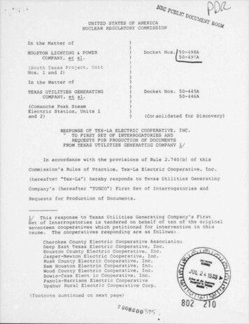
PACK CONTENTS; Tick the appropriate boxes to familiarise yourself with the part names and toconfirm that the parts are included.Essentials 8.5 kW Electric Shower 3 x Wall Plugs 3 x Fixing Screws Documentation 1 x Installation & User Guide1 x Installation Template1 x Guarantee Brochure61 x Essentials 8.5 kWElectric Shower
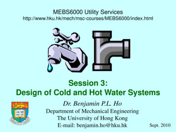
; Tick the appropriate boxes to familiarise yourself with the part names and toconfirm that the parts are included.Essentials 9.5 kW or 10.8 kW Electric Shower 3 x Wall Plugs 3 x Fixing Screws Documentation 1 x Installation & User Guide1 x Installation Template1 x Guarantee Brochure71 x Essentials 9.5 kW or10.8 kW Electric Shower
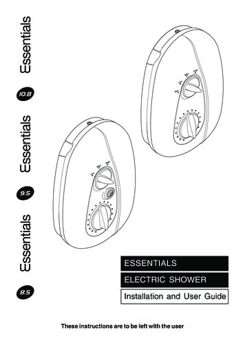
SPECIFICATIONSDimensions96 mm318 mm210 mmNote! 8.5 kW model shown. All dimensions are nominal and in millimetres.837 mm
Wiring Diagram8.5 kW Essentials9.5 and 10.8 kW Essentials9
Plumbing1.2.3.Minimum maintained inlet pressure for satisfactory operation:8.5 kW and 9.5 kW: 0.7 bar (70 kPa).10.8 kW: 1.0 bar (100 kPa).Maximum static inlet pressure: 10 bar (1000 kPa).Minimum static pressure to keep the flow valve closed: 0.5 bar (50 kPa).Electrical1.2.The 8.5 kW and 9.5 kW appliance requires a 40 Amp fuse. The 10.8 kW requiresa 45Amp fuse.The terminal block will not accept cable larger than 10 mm2.Standards and Approvals1.This Essentials shower complies with all of the relevant directives for CE marking.Flow Rate Graph3.These curves are for the specified outputs at 240 V.All appliance heating elements have a manufacturing tolerance. Flow rates maybe above or below those shown on the flow rate graph.The left-hand axis shows temperature rise.Temperature rise (Showering temperature) - (Supply water temperature)Temperature Rise ( C)1.2.10.8 kW9.5 kW8.5 kWFlow Rate (l/min)10
INSTALLATION REQUIREMENTSPlumbing1.2.3.4.5.6.7.8.The Essentials 8.5 kW and 9.5 kW electric showers are designed to operate witha minimum maintained inlet pressure of 0.7 bar (70 kPa) up to a maximumstatic inlet pressure of 10 bar (1000 kPa).The Essentials 10.8 kW electric shower is designed to operate with a minimummaintained inlet pressure of 1.0 bar (100 kPa) up to a maximum static inletpressure of 10 bar (1000 kPa).The appliance is normally connected to the cold water mains-fed supply. However,the water supply can be taken from a cold water storage cistern, provided thereis a minimum maintained inlet head of water of 7 metres for the 8.5kW, 9.5kWand 10 metres for the 10.8kW (the vertical distance from the base of the coldwater storage cistern to the shower fitting handset). To reduce pressure lossesand fluctuations, the cistern-fed water supply must be independent from othersupply draw-offs, and should avoid long horizontal pipe runs and use swept bendsrather than 90 elbows. For further advice please refer to the back cover of thisguide for Essentials Showers contact telephone and fax numbers.The appliance is suitable for installation within the shower area. It is fitted with apressure relief device and must be positioned over a water catchment area withthe controls at a convenient height for the user. The shower fitting should bepositioned so that it discharges down the centre line of the bath, or across theopening of a shower cubicle, and must be directed away from the appliance.The appliance is fitted with an inlet connector assembly that is designed to acceptplumbing supplies from the top or bottom. The water supply can be fed with 15mm pipe or 10 mm microbore pipe, suitably adapted into the inlet connectorassembly. If 10 mm microbore is used, then an allowance for increased pressureloss must be made to ensure that the minimum maintained inlet pressure isachieved.Do not fit the appliance to the wall and tile up to the case. The appliance must befitted onto a finished flat and even wall surface. Otherwise, difficulty may beencountered when fitting the cover, and subsequent operation of the unit couldbe impaired (small pillars moulded on to the back of the case allow air circulation).Use only the inlet connector assembly supplied with the appliance. Do not useany other types of fitting.Refrain from applying excessive force when making any connections. Alwaysprovide mechanical support when making the plumbing connections.This appliance is not designed to be plumbed directly from the rear. For a rearentry supply, add an elbow to the supply pipe and connect it as a rising or fallingsupply.11
9.10.11.12.13.14.15.16.Do not install the appliance in a position where it may become frozen. Theshower unit must not be fitted where it may be exposed to freezing conditions.The shower unit must not be used if you suspect it may be frozen.We recommend that a non-restrictive (free-flowing) isolating valve is fitted in thecold water supply pipe to allow the complete maintenance of the appliance. Donot use a valve with a loose washer plate (jumper) as this can lead to a build upof static pressure.To avoid damage to the case when soldered fittings are used, pre-solder thepipework and fittings before connecting them to the inlet stub.Supply pipework MUST be flushed to clear debris before connecting the appliance.The appliance is fitted with a 1/2" BSP male outlet thread, to accept an Essentialsshower hose.When installed in very hard water areas (above 200 ppm temporary hardness)your installer may advise the installation of a water treatment device, to reducethe effects of limescale formation. Appliance malfunction due to excessivelimescale formation is not covered by the manufacturer’s guarantee. Your localwater company will be able to advise on the hardness of water in your area.A hose retaining soap dish is suppliedto prevent the handset from droppingbelow the spillover level of the bath orshower, which could lead tocontamination from back-siphonage.The supplied hose retaining soap dishshould meet the majority of userrequirements for shower installationswith flexible outlet fittings. However,Hose Retainingthere will be occasions when the hoseSoap Dishretaining soap dish will not provide asuitable solution. In these instancesan outlet double checkvalve must befitted. This will increase the required25 mmsupply pressure typically by 0.1 barminimum(10 kPa).Double checkvalves, fitted in the inletSpilloversupply to the appliance, cause aLevelpressure build-up, which could exceedthe maximum static inlet pressure forthe appliance.Avoid layouts where the shower hose will be sharply kinked. This may reducethe life of the hose.12
Electrical1.2.3.4.5.6.7.8.9.In a domestic installation, the rating of the electricity supply company fuse andthe consumer unit must be adequate for the additional demand. This is a highpower appliance, and it is essential to contact your electricity supply company toensure that the supply is adequate for the appliance. Voltage drop due to localheavy demand will reduce the performance of the shower.The appliance must be earthed by connecting the supply-cable earth conductorto the earth terminal.Supplementary bonding: Within the bathroom or shower room, all accessibleconductive parts of electrical equipment and extraneous conductive parts thatare likely to introduce earth potential, must be electrically bonded to earth usinga minimum cable size of 4.0 mm2 if the cable is not mechanically protected(2.5 mm2 if mechanically protected).The minimum cable size (cross-sectional area) must conform to BS 7671.To obtain full advantage of the power provided by this unit, use the shortestpossible cable route from the consumer unit to the shower.A 30 mA residual current device (RCD) should be fitted. This may be part of theconsumer unit or a separate unit.A separate, permanently connectedsupply must be taken from theconsumer unit to the appliance througha double-pole switch, which has aminimum 3 mm contact separation.The switch can be a ceiling mountedpull-cord type within the shower room,or a wall mounted switch in anadjacent room.DO NOT twist the individual cablecores of the live and neutralconductors, as this will prevent themfrom entering the terminal block.DO NOT exert strain on the terminalblock.Plumbing and Electrical SchematicDO NOT turn-on the electrical supplyuntil the plumbing has been completed.13
INSTALLATION1.2.3.4.5.Determine a position for the shower, at least 200 mm from the ceiling.Put the installation template on the wall and mark the positions of the top twofixing holes. Ensure that there are sufficient lengths of supply pipe and electricalcable to reach the connection points as shown on the template.Remove the installation template and drill the top and side fixing holes. Insertthe supplied wall plugs.Caution! Do not drill into cables or pipes in the wall.Thoroughly flush the supply pipe.On the shower, turn both knobs to the full anti-clockwise position.MedHighLowStop9.5 and 10.8 kW Essentials8.5 kW Essentials6.Remove the three screws that hold thecover on the shower and remove thecover.7.Remove the service tunnel from theshower.8.Determine the direction of the incomingwater supply: falling (entering theshower from the top), or rising (enteringthe shower from the bottom).Do not use an incoming supplyentering the shower directly from theback. Add an elbow to the supply pipeand connect it as a rising or lRotate the inlet connector to suit thedirection of the incoming water supply.Inlet Connector14
10. The case has thinned sections thatcan be removed to allow entry of thesupply pipe and electrical cables.Remove the top thinned section of thecase for a falling supply, or removethe bottom thinned section of theservice tunnel for a rising supply.11. If the electrical cables enter fromabove or below, remove an additionalthinned section for the electrical cable.Do not remove any case if theelectrical cables enter from the back.ThinnedSectionService TunnelThinnedSection12. Secure the shower to the wall looselythrough the top and side fixing holes,using the supplied screws.13. Mark the position of the bottom fixinghole.14. Remove the shower from the wall.Drill the bottom fixing hole and insertthe supplied wall plug.Screws15. Replace the shower on the wall andsecure through the three fixing holes,using the supplied screws.16. Thoroughly flush the mains-fed coldwater supply pipe. The supply mustbe clean and free from debrisBEFORE connecting the appliance.17. Connect the inlet supply pipe to theinlet connector using a 1/2” BSP nipplewith compression nuts and olives(shown) or a push-fit connector.InletConnectorCompressionNutOlive1/2” BSP NippleOliveCompressionNutInlet Supply Pipe15
18. Bring the electrical cables into thecase.NL19. Strip a short section of the electricalcables.20. Fit an earth sleeve to the earth wire.21. Loosen the screws in the terminalblock and insert the bare wires into theclamps.L (Live) Brown WireE (Earth) Green Sleeved WireN (Neutral) Blue WireNote! Do not twist the cores of thewires or strain the cables to make themreach the terminal block.ElectricalCablesScrew22. Tighten the screws in the terminalblock so that they securely clamp thebare wires.ShowerCover23. If necessary, fit an earth bondingclamp to the supply pipe and ensurethat the bonding complies with therelevant regulations in force at the timeof installation.24. Replace the service tunnel.25. Replace the cover. If the cover doesnot fit easily, rotate the knobs slightlyso that they fit onto the spindles. Donot force the cover.26. Tighten the three cover screws.16ScrewsServiceTunnel
COMMISSIONINGCaution! If you are unsure how electric showers work, please read the Operationsection before continuing.1.Turn the shower off by turning thepower knob to Stop (8.5 kW).orTurn the shower off by pressing thepower button. (9.5 kW and 10.8 kW).Make sure that the button is in the offposition.MedHighLowStop8.5 kW9.5 kW and10.8 kWPower button in Power button inthe On position the Off position2.3.4.5.6.7.Turn the temperature knob fullyanticlockwise to cold.Turn on the water supply fully at theisolating valve. Check that water is notleaking from the bottom of the case.Switch on the electrical supply at thedouble pole switch. The light around thepower button will turn on (9.5 kW and10.8 kW only).Turn the shower on by pressing thepower button (9.5 kW and 10.8 kWonly).orTurn the power knob to Low (8.5kW).Check that water flows freely from theshower within a few seconds. If not,refer to the Maintenance section. Thewater from the handset should be atfull force and at a cool temperature.Turn the temperature knob slowlyclockwise to hot. As the knob is rotatedthe flow will be reduced and thetemperature will remain cool – thisshows that the flow regulator assemblyis operating correctly.Turn the temperature knob back fullyanticlockwise to cold.179.5 kW and10.8 kW8.5 kW
8.Turn the power knob to Med. Thetemperature of the water should riseslightly. Allow a few seconds for thewarm water to reach the handset – thisshows that the half power setting isoperating correctly.9. Turn the power knob to High. Thetemperature of the water will rise further– this shows that the full power settingis operating correctly.10. Set the shower temperature by rotatingthe temperature knob as necessary.Turn the knob clockwise for warmerwater and anticlockwise for coolerwater. Allow 10 –15 seconds for theadjusted temperature to reach thehandset.Note! It is normal for the flow rate tochange when the temperature ischanged.11. When the required temperature isreached, turn the power knob to Stop(8.5 kW) to stop the flow. Water willcontinue to flow from the handset fora few seconds, as water is purged fromthe tank. The shower is now set forfuture operation.orWhen the required temperature isreached, press the power button (9.5and 10.8 kW) to stop the flow. Waterwill still continue to flow from thehandset for a few seconds, as wateris purged from the tank.12. Switch off the power at the double poleswitch.Note! It is normal for the shower tomake a slight hissing sound duringoperation. High mains water pressureand high shower temperatures willaffect the tone.188.5 kW8.5 kWCoolerWarmerMedHighLowStop8.5 kW9.5 kW and10.8 kW
OPERATIONAdvice to UsersNote! Read the Important Safety Information section first.Warning! The spray plate holes must be kept clear. Lack of regular spray platecleaning will lead to poor performance and cause early failure of the appliance. Seethe shower fittings User Guide for more information.1. Electric showers work by taking in cold water and passing it over the heatingelements contained in the tank inside the shower.2. The showering temperature is adjusted by turning the temperature control knob,which varies the flow of cold water across the elements. The slower the rate offlow, the warmer the water, and vice versa. The holes in the spray plate of theshower handset should always be kept clean to maintain a consistent flow andstable shower temperatures.3. The appliance is designed to stabilise temperature changes caused by waterpressure fluctuations. These fluctuations can be caused by taps being turned onor off, or toilets being flushed. Under such conditions, average shower temperatureswill be held within a 6 C range, provided that the minimum required pressure ismaintained.4. Seasonal changes in the temperature of the incoming cold water supply and/orfluctuations in mains electrical voltage will effect the temperature of the water.Adjust the temperature knob as necessary to compensate.5. The shower requires a minimum pressure of 0.7 bar (70 kPa) to operate (1 bar(100 kPa) is required for 10.8 kW). At pressures above 0.7 bar (70 kPa), theshower will minimise the temperature fluctuations caused when other draw-offpoints are used. If the flow rate drops below an acceptable level, the heatingelement inside the shower will turn off, resulting in a cold shower.6. If the water temperature reaches an unsafe level, then the thermal switch willturn off the heating element inside the shower. The heating element will be turnedback on when the water temperature drops. The thermal switch will cycle on/off/on unless the flow rate is increased and the temperature of the shower is reduced.This will result in a fluctuating shower temperature.7. Check the shower temperature before entering the shower. The previous usermay have selected a different temperature setting.8. When the shower is first turned on, or the temperature setting is changed, therewill be a slight delay before the water temperature changes.19
8.5 kW Essentials Operating InstructionsTo turn the shower on1. Switch on the electrical supply at thedouble pole switch.2. Turn the power knob to High. Wait15 - 20 seconds for warm water toreach the handset.For electrical economy, set the powerknob to Med. This setting will providesufficient power when the supply watertemperature is warmer, such as in thesummer.For an unheated shower, set the powerknob to Low.To set the shower temperature1. Set the shower temperature by rotatingthe temperature knob as necessary.Turn the knob clockwise for hotterwater and anticlockwise for coolerwater. Wait 10 - 15 seconds for theadjusted temperature to reach thehandset.Note! It is normal for the flow rate tochange when the temperature ischanged.Note! If the water temperature cyclesbetween hot and cold, the temperatureis set too high. This is causing thethermal switch to turn off the heatingelement to reduce the watertemperature. Turn the temperatureknob anticlockwise to reduce the watertemperature.To turn the shower off1. Turn the power knob to Stop.Note! A small amount of water maycontinue to flow from the handset fora few moments.2. Switch off the electrical supply at thedouble pole switch.20
9.5 kW and 10.8 kW Essentials Operating InstructionsTo turn the shower on1. Switch on the electrical supply at thedouble pole switch. The light around thepower button will turn on.2. Turn the shower on by pressing the powerbutton.3. Turn the power knob to High. Wait 15 - 20seconds for warm water to reach thehandset.For electrical economy, set the powerknob to Med. This setting will providesufficient power when the supply watertemperature is warmer, such as in thesummer.For an unheated shower, set the powerknob to Low.To set the shower temperature1. Set the shower temperature by rotatingthe temperature knob as necessary. Turnthe knob clockwise for hotter water andanticlockwise for cooler water. Wait 10–15 seconds for the adjusted temperatureto reach the handset.Note! It is normal for the flow rate tochange when the temperature is changed.Note! If the water temperature cyclesbetween hot and cold, the temperature isset too high. This is causing the thermalswitch to turn off the heating element toreduce the water temperature. Turn thetemperature knob anticlockwise to reducethe water temperature.To turn the shower off1. Turn the shower off by pressing the powerbutton.Note! A small amount of water maycontinue to flow from the handset for afew moments.2. Switch off the electrical supply at thedouble pole switch. The light around thepower button will turn off.21
FAULT DIAGNOSISThe troubleshooting information tabled below gives you details on probable causesand remedies should difficulties be encountered whilst the shower is in operation.Warning! There are no user serviceable components beneath the cover of theappliance.ONLY A COMPETENT TRADESPERSON SHOULD REMOVE THE FRONT COVER!MalfunctionRemedyCauseShower is too hotduring the summer.The incoming water iswarmer in the summer, sothe shower power setting istoo high.Turn the power knob toMedium and adjust thetemperature knob until thedesired temperature isreached.Shower is too hot.The handset sprayplate isblocked.Turningthetemperature knobdoes not affect thewater temperature.The handset sprayplate isblocked.Regularly clean the handsetsprayplate. Refer to theMaintenance section of thehandset manual.Remove and clean the handsetsprayplate. Refer to theMaintenance section of thehandset manual. If the faultpersists, contact the showerinstaller.The water continuesto flow when thedouble pole switch isturned off.Broken diaphragm.Contact your installer toreplace the flow valveassembly.No water or very lowflow rate.The handset sprayplate isblocked.Clean the handset sprayplate.Refer to the Maintenancesection of the handset manual.Open the stop/isolating valvecompletely.The incoming water supplystop valves, or theappliance isolating valve, isclosed.The hose or handset isblocked.22Clear the blockage or replacethe hose or handset.(Continued. . . .)
MalfunctionNo hot water fromshower, with theknobs in anyposition.CauseThe power is off at thedouble pole switch.The fuse is blown or theMCB/RCD has beentripped, indicating apossible electrical fault.Other water outlets arebeingusedduringshowering, causing thewater pressure to dropbelow the minimumrequired.The water pressure isbelow the minimumrequired.Failure of pressure switch,micro switch or thermalswitch.Temperature cyclesbetween hot andcold.The temperature is set toohigh. This is causing thethermal switch to turn offthe heating element toreducethewatertemperature.RemedySwitch on the power at thedouble pole switch.Renew the fuse or reset theMCB/RCD. If the fault p
1. Read all of these instructions and retain this guide for later use. 2. Pass on this guide in the event of change of ownership of the installation site. 3. Follow all warnings, cautions and instructions contained in this guide, and on or inside the appliance. 4. The electrical installation must comp