Transcription
SoftwareArchitecturePatternsMark RichardsREPORT
Software ArchitecturePatternsUnderstanding Common ArchitecturePatterns and When to Use ThemMark Richards
Software Architecture Patternsby Mark RichardsCopyright 2015 O’Reilly Media, Inc. All rights reserved.Printed in the United States of America.Published by O’Reilly Media, Inc., 1005 Gravenstein Highway North, Sebastopol, CA95472.O’Reilly books may be purchased for educational, business, or sales promotional use.Online editions are also available for most titles (http://oreilly.com/safari). For moreinformation, contact our corporate/institutional sales department: 800-998-9938 orcorporate@oreilly.com.Editor: Heather SchererProduction Editor: Colleen LobnerCopyeditor: Amanda KerseyFebruary 2015:Interior Designer: David FutatoCover Designer: Ellie VolckhausenIllustrator: Rebecca DemarestFirst EditionRevision History for the First Edition2015-02-24:2015-03-30:2017-06-22:First ReleaseSecond ReleaseThird ReleaseThe O’Reilly logo is a registered trademark of O’Reilly Media, Inc. Software Architec‐ture Patterns, the cover image, and related trade dress are trademarks of O’ReillyMedia, Inc.While the publisher and the author have used good faith efforts to ensure that theinformation and instructions contained in this work are accurate, the publisher andthe author disclaim all responsibility for errors or omissions, including without limi‐tation responsibility for damages resulting from the use of or reliance on this work.Use of the information and instructions contained in this work is at your own risk. Ifany code samples or other technology this work contains or describes is subject toopen source licenses or the intellectual property rights of others, it is your responsi‐bility to ensure that your use thereof complies with such licenses and/or rights.978-1-491-92424-2[LSI]
Table of ContentsIntroduction. . . . . . . . . . . . . . . . . . . . . . . . . . . . . . . . . . . . . . . . . . . . . . . . . . . v1. Layered Architecture. . . . . . . . . . . . . . . . . . . . . . . . . . . . . . . . . . . . . . . . . 1Pattern DescriptionKey ConceptsPattern ExampleConsiderationsPattern Analysis135782. Event-Driven Architecture. . . . . . . . . . . . . . . . . . . . . . . . . . . . . . . . . . . 11Mediator TopologyBroker TopologyConsiderationsPattern Analysis111417183. Microkernel Architecture. . . . . . . . . . . . . . . . . . . . . . . . . . . . . . . . . . . . 21Pattern DescriptionPattern ExamplesConsiderationsPattern Analysis212324254. Microservices Architecture Pattern. . . . . . . . . . . . . . . . . . . . . . . . . . . . 27Pattern DescriptionPattern TopologiesAvoid Dependencies and OrchestrationConsiderationsPattern Analysis2729323334iii
5. Space-Based Architecture. . . . . . . . . . . . . . . . . . . . . . . . . . . . . . . . . . . . 37Pattern DescriptionPattern DynamicsConsiderationsPattern Analysis38394243A. Pattern Analysis Summary. . . . . . . . . . . . . . . . . . . . . . . . . . . . . . . . . . . 45iv Table of Contents
IntroductionIt’s all too common for developers to start coding an applicationwithout a formal architecture in place. Without a clear and welldefined architecture, most developers and architects will resort tothe de facto standard traditional layered architecture pattern (alsocalled the n-tier architecture), creating implicit layers by separatingsource-code modules into packages. Unfortunately, what oftenresults from this practice is a collection of unorganized source-codemodules that lack clear roles, responsibilities, and relationships toone another. This is commonly referred to as the big ball of mudarchitecture anti-pattern.Applications lacking a formal architecture are generally tightly cou‐pled, brittle, difficult to change, and without a clear vision or direc‐tion. As a result, it is very difficult to determine the architecturalcharacteristics of the application without fully understanding theinner-workings of every component and module in the system.Basic questions about deployment and maintenance are hard toanswer: Does the architecture scale? What are the performancecharacteristics of the application? How easily does the applicationrespond to change? What are the deployment characteristics of theapplication? How responsive is the architecture?Architecture patterns help define the basic characteristics andbehavior of an application. For example, some architecture patternsnaturally lend themselves toward highly scalable applications,whereas other architecture patterns naturally lend themselvestoward applications that are highly agile. Knowing the characteris‐tics, strengths, and weaknesses of each architecture pattern is neces‐v
sary in order to choose the one that meets your specific businessneeds and goals.As an architect, you must always justify your architecture decisions,particularly when it comes to choosing a particular architecture pat‐tern or approach. The goal of this report is to give you enough infor‐mation to make and justify that decision.vi Introduction
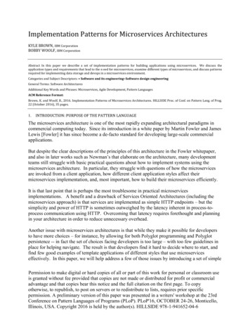
CHAPTER 1Layered ArchitectureThe most common architecture pattern is the layered architecturepattern, otherwise known as the n-tier architecture pattern. Thispattern is the de facto standard for most Java EE applications andtherefore is widely known by most architects, designers, and devel‐opers. The layered architecture pattern closely matches the tradi‐tional IT communication and organizational structures found inmost companies, making it a natural choice for most business appli‐cation development efforts.Pattern DescriptionComponents within the layered architecture pattern are organizedinto horizontal layers, each layer performing a specific role withinthe application (e.g., presentation logic or business logic). Althoughthe layered architecture pattern does not specify the number andtypes of layers that must exist in the pattern, most layered architec‐tures consist of four standard layers: presentation, business, persis‐tence, and database (Figure 1-1). In some cases, the business layerand persistence layer are combined into a single business layer, par‐ticularly when the persistence logic (e.g., SQL or HSQL) is embed‐ded within the business layer components. Thus, smallerapplications may have only three layers, whereas larger and morecomplex business applications may contain five or more layers.Each layer of the layered architecture pattern has a specific role andresponsibility within the application. For example, a presentationlayer would be responsible for handling all user interface and1
browser communication logic, whereas a business layer would beresponsible for executing specific business rules associated with therequest. Each layer in the architecture forms an abstraction aroundthe work that needs to be done to satisfy a particular businessrequest. For example, the presentation layer doesn’t need to knowor worry about how to get customer data; it only needs to displaythat information on a screen in particular format. Similarly, thebusiness layer doesn’t need to be concerned about how to formatcustomer data for display on a screen or even where the customerdata is coming from; it only needs to get the data from the persis‐tence layer, perform business logic against the data (e.g., calculatevalues or aggregate data), and pass that information up to the pre‐sentation layer.Figure 1-1. Layered architecture patternOne of the powerful features of the layered architecture pattern isthe separation of concerns among components. Components withina specific layer deal only with logic that pertains to that layer. Forexample, components in the presentation layer deal only with pre‐sentation logic, whereas components residing in the business layerdeal only with business logic. This type of component classificationmakes it easy to build effective roles and responsibility models intoyour architecture, and also makes it easy to develop, test, govern,and maintain applications using this architecture pattern due towell-defined component interfaces and limited component scope.2 Chapter 1: Layered Architecture
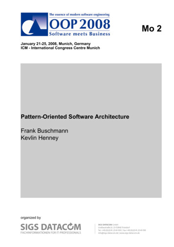
Key ConceptsNotice in Figure 1-2 that each of the layers in the architecture ismarked as being closed. This is a very important concept in the lay‐ered architecture pattern. A closed layer means that as a requestmoves from layer to layer, it must go through the layer right below itto get to the next layer below that one. For example, a request origi‐nating from the presentation layer must first go through the busi‐ness layer and then to the persistence layer before finally hitting thedatabase layer.Figure 1-2. Closed layers and request accessSo why not allow the presentation layer direct access to either thepersistence layer or database layer? After all, direct database accessfrom the presentation layer is much faster than going through abunch of unnecessary layers just to retrieve or save database infor‐mation. The answer to this question lies in a key concept knownas layers of isolation.The layers of isolation concept means that changes made in onelayer of the architecture generally don’t impact or affect componentsin other layers: the change is isolated to the components within thatlayer, and possibly another associated layer (such as a persistencelayer containing SQL). If you allow the presentation layer directaccess to the persistence layer, then changes made to SQL within theKey Concepts 3
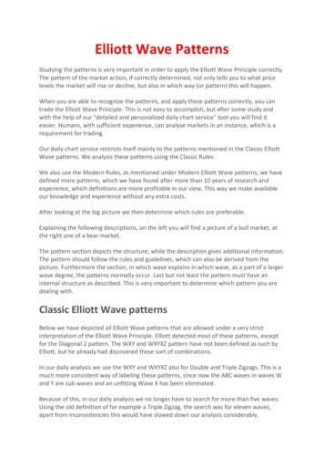
persistence layer would impact both the business layer and the pre‐sentation layer, thereby producing a very tightly coupled applicationwith lots of interdependencies between components. This type ofarchitecture then becomes very hard and expensive to change.The layers of isolation concept also means that each layer is inde‐pendent of the other layers, thereby having little or no knowledge ofthe inner workings of other layers in the architecture. To understandthe power and importance of this concept, consider a large refactor‐ing effort to convert the presentation framework from JSP (JavaServer Pages) to JSF (Java Server Faces). Assuming that the contracts(e.g., model) used between the presentation layer and the businesslayer remain the same, the business layer is not affected by the refac‐toring and remains completely independent of the type of userinterface framework used by the presentation layer.While closed layers facilitate layers of isolation and therefore helpisolate change within the architecture, there are times when it makessense for certain layers to be open. For example, suppose you wantto add a shared-services layer to an architecture containing com‐mon service components accessed by components within the busi‐ness layer (e.g., data and string utility classes or auditing and loggingclasses). Creating a services layer is usually a good idea in this casebecause architecturally it restricts access to the shared services to thebusiness layer (and not the presentation layer). Without a separatelayer, there is nothing architecturally that restricts the presentationlayer from accessing these common services, making it difficult togovern this access restriction.In this example, the new services layer would likely reside below thebusiness layer to indicate that components in this services layer arenot accessible from the presentation layer. However, this presents aproblem in that the business layer is now required to go through theservices layer to get to the persistence layer, which makes no sense atall. This is an age-old problem with the layered architecture, and issolved by creating open layers within the architecture.As illustrated in Figure 1-3, the services layer in this case is markedas open, meaning requests are allowed to bypass this open layer andgo directly to the layer below it. In the following example, since theservices layer is open, the business layer is now allowed to bypass itand go directly to the persistence layer, which makes perfect sense.4 Chapter 1: Layered Architecture
Figure 1-3. Open layers and request flowLeveraging the concept of open and closed layers helps define therelationship between architecture layers and request flows and alsoprovides designers and developers with the necessary information tounderstand the various layer access restrictions within the architec‐ture. Failure to document or properly communicate which layers inthe architecture are open and closed (and why) usually results intightly coupled and brittle architectures that are very difficult to test,maintain, and deploy.Pattern ExampleTo illustrate how the layered architecture works, consider a requestfrom a business user to retrieve customer information for a particu‐lar individual as illustrated in Figure 1-4. The black arrows showthe request flowing down to the database to retrieve the customerdata, and the red arrows show the response flowing back up to thescreen to display the data. In this example, the customer informa‐tion consists of both customer data and order data (orders placed bythe customer).Pattern Example 5
The customer screen is responsible for accepting the request and dis‐playing the customer information. It does not know where the datais, how it is retrieved, or how many database tables must be queriesto get the data. Once the customer screen receives a request to getcustomer information for a particular individual, it then forwardsthat request onto the customer delegate module. This module isresponsible for knowing which modules in the business layer canprocess that request and also how to get to that module and whatdata it needs (the contract). The customer object in the business layeris responsible for aggregating all of the information needed by thebusiness request (in this case to get customer information). Thismodule calls out to the customer dao (data access object) module inthe persistence layer to get customer data, and also the order daomodule to get order information. These modules in turn executeSQL statements to retrieve the corresponding data and pass it backup to the customer object in the business layer. Once the customerobject receives the data, it aggregates the data and passes that infor‐mation back up to the customer delegate, which then passes thatdata to the customer screen to be presented to the user.Figure 1-4. Layered architecture exampleFrom a technology perspective, there are literally dozens of waysthese modules can be implemented. For example, in the Java plat‐form, the customer screen can be a (JSF) Java Server Faces screen6 Chapter 1: Layered Architecture
coupled with the customer delegate as the managed bean compo‐nent. The customer object in the business layer can be a local Springbean or a remote EJB3 bean. The data access objects illustrated inthe previous example can be implemented as simple POJO’s (PlainOld Java Objects), MyBatis XML Mapper files, or even objectsencapsulating raw JDBC calls or Hibernate queries. From a Micro‐soft platform perspective, the customer screen can be an ASP (activeserver pages) module using the .NET framework to access C# mod‐ules in the business layer, with the customer and order data accessmodules implemented as ADO (ActiveX Data Objects).ConsiderationsThe layered architecture pattern is a solid general-purpose pattern,making it a good starting point for most applications, particularlywhen you are not sure what architecture pattern is best suited foryour application. However, there are a couple of things to considerfrom an architecture standpoint when choosing this pattern.The first thing to watch out for is what is known as the architecturesinkhole anti-pattern. This anti-pattern describes the situation whererequests flow through multiple layers of the architecture as simplepass-through processing with little or no logic performed withineach layer. For example, assume the presentation layer responds to arequest from the user to retrieve customer data. The presentationlayer passes the request to the business layer, which simply passesthe request to the persistence layer, which then makes a simple SQLcall to the database layer to retrieve the customer data. The data isthen passed all the way back up the stack with no additional pro‐cessing or logic to aggregate, calculate, or transform the data.Every layered architecture will have at least some scenarios that fallinto the architecture sinkhole anti-pattern. The key, however, is toanalyze the percentage of requests that fall into this category. The80-20 rule is usually a good practice to follow to determine whetheror not you are experiencing the architecture sinkhole anti-pattern. Itis typical to have around 20 percent of the requests as simple passthrough processing and 80 percent of the requests having somebusiness logic associated with the request. However, if you find thatthis ratio is reversed and a majority of your requests are simple passthrough processing, you might want to consider making some of theConsiderations 7
architecture layers open, keeping in mind that it will be more diffi‐cult to control change due to the lack of layer isolation.Another consideration with the layered architecture pattern is that ittends to lend itself toward monolithic applications, even if you splitthe presentation layer and business layers into separate deployableunits. While this may not be a concern for some applications, it doespose some potential issues in terms of deployment, general robust‐ness and reliability, performance, and scalability.Pattern AnalysisThe following table contains a rating and analysis of the commonarchitecture characteristics for the layered architecture pattern. Therating for each characteristic is based on the natural tendencyfor that characteristic as a capability based on a typical implementa‐tion of the pattern, as well as what the pattern is generally knownfor. For a side-by-side comparison of how this pattern relates toother patterns in this report, please refer to Appendix A at the endof this report.Overall agilityRating: LowAnalysis: Overall agility is the ability to respond quickly to aconstantly changing environment. While change can be isolatedthrough the layers of isolation feature of this pattern, it is stillcumbersome and time-consuming to make changes in thisarchitecture pattern because of the monolithic nature of mostimplementations as well as the tight coupling of componentsusually found with this pattern.Ease of deploymentRating: LowAnalysis: Depending on how you implement this pattern,deployment can become an issue, particularly for larger applica‐tions. One small change to a component can require aredeployment of the entire application (or a large portion of theapplication), resulting in deployments that need to be planned,scheduled, and executed during off-hours or on weekends.As such, this pattern does not easily lend itself toward a contin‐uous delivery pipeline, further reducing the overall rating fordeployment.8 Chapter 1: Layered Architecture
TestabilityRating: HighAnalysis: Because components belong to specific layers in thearchitecture, other layers can be mocked or stubbed, makingthis pattern is relatively easy to test. A developer can mock apresentation component or screen to isolate testing within abusiness component, as well as mock the business layer to testcertain screen functionality.PerformanceRating: LowAnalysis: While it is true some layered architectures can per‐form well, the pattern does not lend itself to high-performanceapplications due to the inefficiencies of having to go throughmultiple layers of the architecture to fulfill a business request.ScalabilityRating: LowAnalysis: Because of the trend toward tightly coupled and mon‐olithic implementations of this pattern, applications build usingthis architecture pattern are generally difficult to scale. You canscale a layered architecture by splitting the layers into separatephysical deployments or replicating the entire application intomultiple nodes, but overall the granularity is too broad, makingit expensive to scale.Ease of developmentRating: HighAnalysis: Ease of development gets a relatively high score,mostly because this pattern is so well known and is not overlycomplex to implement. Because most companies develop appli‐cations by separating skill sets by layers (presentation, business,database), this pattern becomes a natural choice for mostbusiness-application development. The connection between acompany’s communication and organization structure and theway it develops software is outlined is what is called Conway’slaw. You can Google “Conway’s law" to get more informationabout this fascinating correlation.Pattern Analysis 9
CHAPTER 2Event-Driven ArchitectureThe event-driven architecture pattern is a popular distributedasynchronous architecture pattern used to produce highly scalableapplications. It is also highly adaptable and can be used for smallapplications and as well as large, complex ones. The event-drivenarchitecture is made up of highly decoupled, single-purpose eventprocessing components that asynchronously receive and processevents.The event-driven architecture pattern consists of two main topolo‐gies, the mediator and the broker. The mediator topology is com‐monly used when you need to orchestrate multiple steps within anevent through a central mediator, whereas the broker topology isused when you want to chain events together without the use of acentral mediator. Because the architecture characteristics and imple‐mentation strategies differ between these two topologies, it is impor‐tant to understand each one to know which is best suited for yourparticular situation.Mediator TopologyThe mediator topology is useful for events that have multiple stepsand require some level of orchestration to process the event. Forexample, a single event to place a stock trade might require you tofirst validate the trade, then check the compliance of that stock tradeagainst various compliance rules, assign the trade to a broker, calcu‐late the commission, and finally place the trade with that broker. Allof these steps would require some level of orchestration to deter‐11
mine the order of the steps and which ones can be done serially andin parallel.There are four main types of architecture components within themediator topology: event queues, an event mediator, event channels,and event processors. The event flow starts with a client sending anevent to an event queue, which is used to transport the event to theevent mediator. The event mediator receives the initial event andorchestrates that event by sending additional asynchronous eventsto event channels to execute each step of the process. Event process‐ors, which listen on the event channels, receive the event from theevent mediator and execute specific business logic to process theevent. Figure 2-1 illustrates the general mediator topology of theevent-driven architecture pattern.Figure 2-1. Event-driven architecture mediator topologyIt is common to have anywhere from a dozen to several hundredevent queues in an event-driven architecture. The pattern doesnot specify the implementation of the event queue component; itcan be a message queue, a web service endpoint, or any combinationthereof.There are two types of events within this pattern: an initial event anda processing event. The initial event is the original event received by12 Chapter 2: Event-Driven Architecture
the mediator, whereas the processing events are ones thatare generated by the mediator and received by the event-processingcomponents.The event-mediator component is responsible for orchestratingthe steps contained within the initial event. For each step in the ini‐tial event, the event mediator sends out a specific processing eventto an event channel, which is then received and processed by theevent processor. It is important to note that the event mediatordoesn’t actually perform the business logic necessary to process theinitial event; rather, it knows of the steps required to process the ini‐tial event.Event channels are used by the event mediator to asynchronouslypass specific processing events related to each step in the initialevent to the event processors. The event channels can be either mes‐sage queues or message topics, although message topics are mostwidely used with the mediator topology so that processing eventscan be processed by multiple event processors (each performing adifferent task based on the processing event received).The event processor components contain the application businesslogic necessary to process the processing event. Event processors areself-contained, independent, highly decoupled architecture compo‐nents that perform a specific task in the application or system.While the granularity of the event-processor component can varyfrom fine-grained (e.g., calculate sales tax on an order) to coarsegrained (e.g., process an insurance claim), it is important to keep inmind that in general, each event-processor component should per‐form a single business task and not rely on other event processors tocomplete its specific task.The event mediator can be implemented in a variety of ways. As anarchitect, you should understand each of these implementationoptions to ensure that the solution you choose for the event media‐tor matches your needs and requirements.The simplest and most common implementation of the event medi‐ator is through open source integration hubs such as Spring Integra‐tion, Apache Camel, or Mule ESB. Event flows in these open sourceintegration hubs are typically implemented through Java code or aDSL (domain-specific language). For more sophisticated mediationand orchestration, you can use BPEL (business process executionlanguage) coupled with a BPEL engine such as the open sourceMediator Topology 13
Apache ODE. BPEL is a standard XML-like language that describesthe data and steps required for processing an initial event. For verylarge applications requiring much more sophisticated orchestration(including steps involving human interactions), you can implementthe event mediator using a business process manager (BPM) suchas jBPM.Understanding your needs and matching them to the correct eventmediator implementation is critical to the success of any eventdriven architecture using this topology. Using an open source inte‐gration hub to do very complex business process managementorchestration is a recipe for failure, just as is implementing a BPMsolution to perform simple routing logic.To illustrate how the mediator topology works, suppose you areinsured through an insurance company and you decide to move. Inthis case, the initial event might be called something like relocationevent. The steps involved in processing a relocation event are con‐tained within the event mediator as shown in Figure 2-2. For eachinitial event step, the event mediator creates a processing event (e.g.,change address, recalc quote, etc.), sends that processing event to theevent channel and waits for the processing event to be processed bythe corresponding event processor (e.g., customer process, quoteprocess, etc.). This process continues until all of the steps in the ini‐tial event have been processed. The single bar over the recalc quoteand update claims steps in the event mediator indicates that thesesteps can be run at the same time.Broker TopologyThe broker topology differs from the mediator topology in thatthere is no central event mediator; rather, the message flow is dis‐tributed across the event processor components in a chain-likefashion through a lightweight message broker (e.g., ActiveMQ,HornetQ, etc.). This topology is useful when you have a relativelysimple event processing flow and you do not want (or need) centralevent orchestration.There are two main types of architecture components within thebroker topology: a broker component and an event processor compo‐nent. The broker component can be centralized or federated andcontains all of the event channels that are used within the event flow.14 Chapter 2: Event-Driven Architecture
The event channels contained within the broker component can bemessage queues, message topics, or a combination of both.Figure 2-2. Mediator topology exampleThis topology is illustrated in Figure 2-3. As you can see from thediagram, there is no central event-mediator component controllingand orchestrating the initial event; rather, each event-processorcomponent is responsible for processing an event and publishing anew event indicating the action it just performed. For example, anevent processor that balances a portfolio of stocks may receive aninitial event called stock split. Based on that initial event, the eventprocessor may do some portfolio rebalancing, and then publish anew event to the broker called rebalance portfolio, which would thenbe picked up by a different event processor. Note that there may betimes when an event is published by an event processor but notpicked up by any another event processor. This is common whenyou are evolving an application or providing for future functionalityand extensions.Broker Topology 15
Figure 2-3. Event-driven architecture broker topologyTo illustrate how the broker topology works, we’ll use the sameexample as in the mediator topology (an insured person moves).Since there is no central event mediator to receive the initial event inthe broker topology, the customer-process component receives theevent directly, changes the customer address, and sends out an eventsaying it changed a customer’s address (e.g., change address event).In this example, there are two event processors that are interested inthe change address event: the quote process and the claims process.The quote processor component recalculates the new autoinsurance rates based on the address change and publishes an eventto the rest of the system indicating what it did (e.g., recalc quoteevent). The claims processing component, on the other hand,receives the same change address event, but
the application (e.g., presentation logic or business logic). Although the layered architecture pattern does not specify the number and types of layers that must exist in the pattern, most layered architec‐ tures consist of four standard layers: presentation, business, persis‐ tence, and