Transcription
Spiral Development:Experience, Principles,and RefinementsSpiral Development WorkshopFebruary 9, 2000Barry Boehm, edited by Wilfred J. HansenJuly 2000SPECIAL REPORTCMU/SEI-2000-SR-008
Pittsburgh, PA 15213-3890Spiral Development:Experience, Principles,and RefinementsSpiral Development WorkshopFebruary 9, 2000CMU/SEI-2000-SR-008Barry Boehm, edited by Wilfred J. HansenJuly 2000COTS-Based SystemsUnlimited distribution subject to the copyright.
This report was prepared for theSEI Joint Program OfficeHQ ESC/DIB5 Eglin StreetHanscom AFB, MA 01731-2116The ideas and findings in this report should not be construed as an official DoD position. It is published in the interest ofscientific and technical information exchange.FOR THE COMMANDERNorton L. Compton, Lt Col., USAFSEI Joint Program OfficeThis work is sponsored by the U.S. Department of Defense. The Software Engineering Institute is afederally funded research and development center sponsored by the U.S. Department of Defense.Copyright 2000 by Carnegie Mellon University.NO WARRANTYTHIS CARNEGIE MELLON UNIVERSITY AND SOFTWARE ENGINEERING INSTITUTE MATERIAL ISFURNISHED ON AN “AS-IS” BASIS. CARNEGIE MELLON UNIVERSITY MAKES NO WARRANTIES OF ANYKIND, EITHER EXPRESSED OR IMPLIED, AS TO ANY MATTER INCLUDING, BUT NOT LIMITED TO,WARRANTY OF FITNESS FOR PURPOSE OR MERCHANTABILITY, EXCLUSIVITY, OR RESULTS OBTAINEDFROM USE OF THE MATERIAL. CARNEGIE MELLON UNIVERSITY DOES NOT MAKE ANY WARRANTY OFANY KIND WITH RESPECT TO FREEDOM FROM PATENT, TRADEMARK, OR COPYRIGHT INFRINGEMENT.Use of any trademarks in this report is not intended in any way to infringe on the rights of the trademark holder.Internal use. Permission to reproduce this document and to prepare derivative works from this document for internal use isgranted, provided the copyright and “No Warranty” statements are included with all reproductions and derivative works.External use. Requests for permission to reproduce this document or prepare derivative works of this document for externaland commercial use should be addressed to the SEI Licensing Agent.This work was created in the performance of Federal Government Contract Number F19628-95-C-0003 with CarnegieMellon University for the operation of the Software Engineering Institute, a federally funded research and developmentcenter. The Government of the United States has a royalty-free government-purpose license to use, duplicate, or disclose thework, in whole or in part and in any manner, and to have or permit others to do so, for government purposes pursuant to thecopyright license under the clause at 52.227-7013.For information about purchasing paper copies of SEI reports, please visit the publications portion of our Web ml).
Table of ContentsAbstract1Introduction1.1 Success Stories from the Workshop1.2 The Spiral Development Model2The Invariants and Their Variants52.1 Spiral Invariant 1: Concurrent Determinationof Key Artifacts (Ops Concept, Requirements,Plans, Design, Code)62.2 Spiral Invariant 2: Each Cycle DoesObjectives, Constraints, Alternatives, Risks,Review, Commitment to Proceed92.3 Spiral Invariant 3: Level of Effort Driven byRisk Considerations112.4 Spiral Invariant 4: Degree of Detail Driven byRisk Considerations132.5 Spiral Invariant 5: Use of Anchor PointMilestones: LCO, LCA, IOC142.6 Spiral Invariant 6: Emphasis on System andLife Cycle Activities and Artifacts163Anchor Point Milestones3.1 Detailed Descriptions3.2 Relationships to Other Process ModelsEvolutionary nal RUP Phases22WinWin Spiral Model23MBASE Electronic Process Guide24Summary27References31Acronyms35i
iiCMU/SEI-2000-SR-008
List of FiguresFigure 1: Original Diagram of Spiral Development 2Figure 2: Two System Designs: Cost vs. ResponseTime7Figure 3: Models Excluded: Sequential Phaseswithout Key Stakeholders10Figure 4: Pre-Ship Test Risk Exposure12Figure 5: Scientific American Order Processing17Figure 6: Anchor Points and the Rational RUPPhases22Figure 7: The WinWin Spiral Model23Figure 8 EPG Top-Level Outline of Activities,Artifacts, and Agents25Figure 9 EPG Diagram of the Inception Phase25Figure 10 EPG Outline and Description of RiskDriven Analysis26Figure 11 The “Outputs”Section of the Descriptionon the Right of Figure 10.26CMU/SEI-2000-SR-008iii
ivCMU/SEI-2000-SR-008
List of TablesCMU/SEI-2000-SR-008Table 1:WinWin Spiral Anchor Points (with riskdriven level of detail for each element) 20Table 2:Invariants of Spiral Processes: Name,Rationale, and Variants28Table 3:Hazardous Spiral Look-Alikes29v
viCMU/SEI-2000-SR-008
AbstractSpiral development is a family of software development processes characterized by repeatedly iterating a set of elemental development processes and managing risk so it is activelybeing reduced. This paper characterizes spiral development by enumerating a few “invariant”properties that any such process must exhibit. For each, a set of “variants” is also presented,demonstrating a range of process definitions in the spiral development family. Each invariantexcludes one or more “hazardous spiral look-alike” models, which are also outlined. Thisreport also shows how the spiral model can be used for a more cost-effective incrementalcommitment of funds, via an analogy of the spiral model to stud poker. An important andrelatively recent innovation to the spiral model has been the introduction of anchor pointmilestones. The latter part of the paper describes and discusses these.Editor’s Note: This document began as a set of slides prepared and annotated by Barry Boehm andpresented by him at the Spiral Development Workshop, February 2000. With Barry's consent, I undertook the task of converting these slides to the text you now see. The original slides are available onthe workshop Web site: I-2000-SR-008vii
viiiCMU/SEI-2000-SR-008
1 IntroductionThis presentation opened the Workshop on Spiral Development Experience and Implementation Challenges held by the University of Southern California (USC) and the Software Engineering Institute (SEI) on February 9-11, 2000 at USC. The workshop brought togetherleading executives and practitioners with experience in spiral development of softwareintensive systems in the commercial, aerospace, and government sectors. Its objectives wereto distill the participants' experiences into a set of critical success factors for implementingand conducting spiral development, and to identify the most important needs, opportunities,and actions to expedite organizations' transition to successful spiral development. For theworkshop, “development” was defined to include life cycle evolution of software-intensivesystems and such related practices as legacy system replacement and integration of commercial-off-the-shelf (COTS) components. Although of greatest utility for software developments, the spiral model can also be used to develop hardware or integrate software, hardware,and systems.To provide a starting point for addressing the workshop objectives, I have tried in this talk todistill my experiences in developing and transitioning the spiral model at TRW; in using it insystem acquisitions at the Defense Advanced Research Projects Agency (DARPA); in tryingto refine it to address problems that people have had in applying it in numerous commercial,aerospace, and government contexts; and in working with the developers of major elaborations and refinements of the spiral model such as the Software Productivity Consortium's(SPC) Evolutionary Spiral Process (SPC) [SPC 94] and Rational, Inc.'s Rational Unified Process (RUP) [Royce 98, Kruchten 98, Jacobson 99]. I've modified the presentation somewhatto reflect the experience and discussions at the Workshop and this report is a further refinement.One of the findings of the workshop was a need for a clear and widely understood definitionof the spiral development model. The characteristics of the model noted here should sufficeas a starting point for this work.1.1 Success Stories from the WorkshopA number of projects and project frameworks successfully exploiting the spiral model werepresented at the workshop, often with supplementary material elsewhere. C-Bridge’s RAPIDapproach has been used successfully to develop e-commerce applications in 12-24 weeks. ItsDefine, Design, Develop, and Deploy phases use the equivalent of the anchor point milestones (see Section 2.5) as phase gates [Leinbach 00]. The large spiral telecommunicationsCMU/SEI-2000-SR-0081
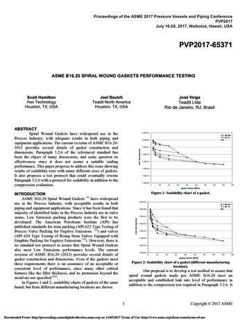
applications discussed in [Bernstein 00] and [DeMillo 00] use a complementary best practiceas their anchor point milestones: the AT&T/Lucent/Telcordia Architecture Review Board process [AT&T 93]. Xerox’s Time-to-Market process uses the anchor point milestones as hardware-software synchronization points for its printer business line [Hantos 00].Several successful large aerospace spiral projects were also discussed. The best documentedof these is the CCPDS-R project discussed in [Royce 98]. Its Ada Process Model was thepredecessor of the Rational Unified Process and USC MBASE approach, which have bothbeen used on a number of successful spiral projects [Jacobson 99, Boehm 98], as has the SPCEvolutionary Spiral Process [SPC 94]. Further successful large aerospace spiral projectswere presented by SAIC and TRW [Kitaoka 00, Bostelaar VESIDENTIFY,RESOLVE RISKSRISK ANALYSISRISK ANALYSISRISK KPROTOTYPE 3ANAL.PROTOTYPE 2PROTOTYPE1REVIEWRQTS PLANLIFE CYCLEPLANDEVELOPMENT PLANEMULATIONSCONCEPT PLAN NEXTPHASESINTEGRATIONAND TESTPLANDESIGN VALIDATIONAND VERIFICATIONIMPLEMENTATIONACCEPTANCE TESTUNITTESTINTEGRATION ANDTESTDEVELOP, VERIFYNEXT LEVEL PRODUCTFigure 1: Original Diagram of Spiral Development2CMU/SEI-2000-SR-008
1.2 The Spiral Development ModelFigure 1 is a redrawing of the original spiral model diagram published by Boehm [Boehm88]. It captures the major spiral model features: cyclic concurrent engineering; risk drivendetermination of process and product; growing a system via risk-driven experimentation andelaboration; and lowering development cost by early elimination of nonviable alternativesand rework avoidance. As a result of planning and risk analysis, different projects maychoose different processes. That is, the spiral model is actually a risk-driven process modelgenerator, in which different risk patterns can lead to choosing incremental, waterfall, evolutionary prototyping, or other subsets of the process elements in the spiral model diagram.For a number of reasons, however, the spiral model is not universally understood. For instance, Figure 1 contains some oversimplifications that have caused a number of misconceptions to propagate about the spiral model. These misconceptions may fit a few rare risk patterns, but are definitely not true for most risk patterns. The most significant misconceptionsto avoid are: that the spiral is just a sequence of waterfall increments; that everything on theproject follows a single spiral sequence; that every element in the diagram needs to be visitedin the order indicated; and that there can be no backtracking to revisit previous decisions. Inaddition to these misconceptions, other similar— but hazardously distinct— processes havebeen held up as spiral processes.To promote understanding and effective use of the spiral model, this report more preciselycharacterizes the spiral model. We begin with a simple overview definition to capture theessence of the model:The spiral development model is a risk-driven process model generator.It is used to guide multi-stakeholder concurrent engineering of softwareintensive systems. It has two main distinguishing features. One is acyclic approach for incrementally growing a system's degree ofdefinition and implementation while decreasing its degree of risk. Theother is a set of anchor point milestones for ensuring stakeholdercommitment to feasible and mutually satisfactory system solutions.Risks are situations or possible events that can cause a project to fail to meet its goals.They range in impact from trivial to fatal and in likelihood from certain to improbable. A risk management plan enumerates the risks and prioritizes them in degree ofimportance, as measured by a combination of the impact and likelihood of each. Foreach risk the plan also states a mitigation strategy to deal with the risk. For instance,the risk that technology is unready may be mitigated by an appropriate prototype implementation in an early spiral cycle.A process model answers two main questions: What should be done next?CMU/SEI-2000-SR-0083
For how long should it continue?Under the spiral model the answers to these questions are driven by risk considerations andvary from project to project and sometimes from one spiral cycle to the next. Each choice ofanswers generates a different process model. At the start of a cycle, all of the project’s success-critical stakeholders must participate concurrently in reviewing risks and choosing theproject’s process model accordingly. (Risk considerations also apply toward to ensuring thatprogress is not impeded by stakeholders’overparticipation).The cyclic nature of the spiral model was illustrated in Figure 1.Anchor point milestones drive the spiral to progress toward completion and offer a means tocompare progress between one spiral project and another. The second half of the report expands on these milestones. It also presents some experience-based refinements of the spiralmodel developed to address spiral usage problems encountered over the years: evolutionarydevelopment, Rational Unified Process (RUP), the WinWin spiral model, and the ModelBased (System) Architecting and Software Engineering (MBASE) approach.The spiral development model is more precisely characterized in the next section with invariant properties and their variants. Invariant 5 invokes the relatively new concept of “anchorpoint milestones.” These are considered in more depth in the third section. The fourth sectionpresents tables summarizing the material.4CMU/SEI-2000-SR-008
2 The Invariants and Their VariantsThose successfully following the spiral model discipline will find that their cycles invariantlydisplay these six characteristics:1. Concurrent rather than sequential determination of artifacts.2. Consideration in each spiral cycle of the main spiral elements: critical-stakeholder objectives and constraints product and process alternatives risk identification and resolution stakeholder review commitment to proceed3. Using risk considerations to determine the level of effort to be devoted to each activitywithin each spiral cycle.4. Using risk considerations to determine the degree of detail of each artifact produced ineach spiral cycle.5. Managing stakeholder life-cycle commitments with three anchor point milestones: Life Cycle Objectives (LCO) Life Cycle Architecture (LCA) Initial Operational Capability (IOC)6. Emphasis on activities and artifacts for system and life cycle rather than for softwareand initial development.Subsequent sections describe each of these invariants, the critical-success-factor reasons whyit is an essential invariant, and its associated optional variants. Examples are given, includingan analogy with stud poker which demonstrates how the spiral model accommodates costeffective incremental commitment of funds. Many processes are adopted which may seem tobe instances of the spiral model, but lack essential invariants and thus risk failure. Each invariant excludes one or more such process models, which we call “hazardous spiral lookalikes.” They are cataloged and pilloried as part of describing the invariants.CMU/SEI-2000-SR-0085
2.1 Spiral Invariant 1: Concurrent Determination ofKey Artifacts (Ops Concept, Requirements, Plans,Design, Code)Spiral Invariant 1 states that it is success-critical to concurrently determine a compatible andfeasible combination of key artifacts: the operational concept, the system and software requirements, the plans, the system and software architecture and design, and the key codecomponents including COTS, reused components, prototypes, success-critical components,and algorithms.Summary of Invariant 1Why invariantavoids premature sequential commitments tosystem requirements, design, COTS,combination of cost / schedule / performanceExample: "one second response time"Variants1a. Relative amount of each artifact developed in each cycle1b. Number of concurrent mini-cycles in each cycleModels excludedIncremental sequential waterfallswith high risk of violating waterfall model assumptionsWhy is this a success-critical invariant? Because sequential determination of the key artifactswill prematurely overconstrain, and often extinguish, the possibility of developing a systemwhich satisfies the stakeholders’essential success conditions. Examples are premature commitments to hardware platforms, to incompatible combinations of COTS components [Garlan95], and to requirements whose achievability has not been validated, such as the one-secondresponse time requirement Example just below.Variants 1a and 1b indicate that the product and process internals of the concurrent engineering activity are not invariant. For a low technology, interoperability-critical system, the initial spiral products will be requirements-intensive. For a high-technology, more standalonesystem, the initial spiral products will be prototype code-intensive. Also, there is no invariantnumber of mini-cycles (e.g., individual prototypes for COTS, algorithm, or user-interfacerisks) within a given spiral cycle.6CMU/SEI-2000-SR-008
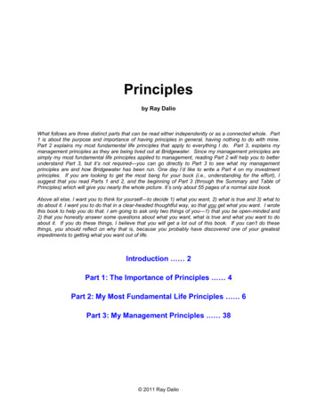
Example: One-Second Response TimeFigure 2 provides an example of the kinds of problems that occur when high-risk requirements are prematurely frozen. In the early 1980s, a large government organization contractedwith TRW to develop an ambitious information system. The system would provide morethan a thousand users, spread across a large building complex, with powerful query andanalysis capabilities for a large and dynamic database. 100MArch. A:Custommany cache processors 50MArch. B:ModifiedClient-ServerOriginal Spec1After Prototyping2345Response Time (sec)Figure 2: Two System Designs: Cost vs. Response TimeTRW and the customer specified the system using a classic sequential-engineering waterfalldevelopment model. Based largely on user need surveys and an oversimplified high-levelperformance analysis, they fixed into the contract a requirement for a system response time ofless than one second.Two thousand pages of requirements later, the software architects found that subsecond performance could only be provided via Architecture A, a highly customized design that attempted to anticipate query patterns and cache copies of data so that each user’s likely datawould be within one second’s reach. The resulting hardware architecture had more than 25super-minicomputers busy caching data according to algorithms whose actual performancedefied easy analysis. The scope and complexity of the hardware-software architecturebrought the estimated cost of the system to nearly 100 million, driven primarily by the requirement for a one-second response time.Faced with this unattractive prospect, the customer and developer decided to develop a prototype of the system’s user interface and representative capabilities to test. The resultsCMU/SEI-2000-SR-0087
showed that a four-second response time would satisfy users 90 percent of the time. A foursecond response time could be achieved with Architecture B, cutting development costs to 30 million [Boehm 00a]. Thus, the premature specification of a one-second response timeinserted the hidden risk of creating an overly expensive and time-consuming system development.Hazardous Spiral Look-Alike: Violation of Waterfall AssumptionsInvariant 1 excludes one model often labeled as a spiral process, but which is actually a “hazardous spiral look-alike.” This is the use of a sequence of incremental waterfall developmentswith a high risk of violating the underlying assumptions of the waterfall model. These assumptions are1. The requirements are knowable in advance of implementation.2. The requirements have no unresolved, high-risk implications, such as risks due toCOTS choices, cost, schedule, performance, safety, security, user interfaces, andorganizational impacts.3. The nature of the requirements will not change very much either during development orevolution.4. The requirements are compatible with all the key system stakeholders’expectations,including users, customer, developers, maintainers, investors.5. The right architecture for implementing the requirements is well understood.6. There is enough calendar time to proceed sequentially.These assumptions must be met by a project if the waterfall model is to succeed. If all ofthese are true, then it is a project risk not to specify the requirements, and the waterfall modelbecomes a risk-driven special case of the spiral model. If any of the assumptions are untrue,then specifying a complete set of requirements in advance of risk resolution will commit aproject to assumptions/requirements mismatches that will lead the project into trouble.Assumption 1— the requirements are knowable in advance of implementation— is generallyuntrue for new user-interactive systems, because of the IKIWISI syndrome. When asked fortheir required screen layout for a new decision-support system, users will generally say, “Ican’t tell you, but I’ll know it when I see it (IKIWISI).” In such cases, a concurrentprototyping/requirements/architecture approach is essential.The effects of invalidity in Assumptions 2, 4, and 5 are well illustrated by the example inFigure 2. The one-second response time requirement was unresolved and high-risk. It wascompatible with the users’expectations, but not with the customer’s budget expectations.And the need for an expensive custom architecture was not understood in advance.The effects of invalidity in Assumptions 3 and 6 are well illustrated by electronic commerceprojects. In these projects the volatility of technology and the marketplace is so high that requirements and traceability updates will swamp the project in overhead. Furthermore, theamount of initial calendar time it takes to work out a complete set of detailed requirements8CMU/SEI-2000-SR-008
that are likely to change several times downstream is not a good investment of the scarce timeto market available to develop an initial operational capability.2.2 Spiral Invariant 2: Each Cycle Does Objectives,Constraints, Alternatives, Risks, Review,Commitment to ProceedSpiral Invariant 2 identifies the activities in each quadrant of the original spiral diagram thatneed to be done in each spiral cycle. These include consideration of critical-stakeholder objectives and constraints; elaboration and evaluation of project and process alternatives forachieving the objectives subject to the constraints; identification and resolution of risks attendant on choices of alternative solutions; and stakeholders’review and commitment to proceedbased on satisfaction of their critical objectives and constraints. If all of these are not considered, the project may be prematurely committed to alternatives that are either unacceptable tokey stakeholders or overly risky.Summary of Invariant 2Why invariantAvoids commitment to stakeholder-unacceptableor overly risky alternatives.Avoids wasted effort in elaborating unsatisfactory alternativesExample: "Windows-only COTS"Variants2a. Choice of risk resolution techniques:prototyping, simulation, modeling, benchmarking,reference checking, etc.2b. Level of effort on each activity within each cycleModels excludedSequential phases with key stakeholders excludedProject groups must also guard against having the appearance but not the reality ofstakeholder participation by accepting an unqualified member of an integrated product team(IPT). A good set of criteria for qualified IPT members-— as described in Boehm and adoptedin USAF [Boehm 98, USAF 00]— is to ensure that IPT members are representative (of organizational rather than personal positions), empowered (to make commitments which will behonored by their organizations), knowledgeable (of their organization's critical success factors), collaborative, and committed.Spiral Invariant 2 does not mandate particular generic choices of risk resolution techniques.However, there are risk management guidelines that suggest, for example, the best-candidateCMU/SEI-2000-SR-0089
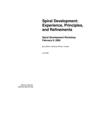
risk resolution techniques for the major sources of project risk [Boehm 89a]. This invariantalso does not mandate particular levels of effort for the activities performed during each cycle. Levels must be balanced between the risks of learning too little and the risks of wastingtime and effort gathering marginally useful information.Example: Windows-Only COTSIgnoring Invariant 2, can lead to a good deal of wasted effort in elaborating an alternative thatcould have been shown earlier to be unsatisfactory. One of the current USC digital libraryprojects is developing a web-based viewer for oversized artifacts (e.g., newspapers, large images). The initial prototype featured a tremendously powerful and high-speed viewing capability, based on a COTS product called ER Mapper. The initial project review approved selection of this COTS product, even though it only ran well on Windows platforms, and theLibrary had significant Macintosh and UNIX user communities. This decision was based oninitial indications that Mac and UNIX versions of ER Mapper would be available soon.However, subsequent investigations indicated that it would be a long time before such Macand UNIX capabilities would become available. At a subsequent review, ER Mapper wasdropped in favor of a less powerful but fully portable COTS product, Mr. SID, but only aftera good deal of effort was wasted on elaborating the ER Mapper solution. If a representativeof the Mac or UNIX user community had been involved in the early project decisions, thehomework leading to choosing Mr. SID would have been done earlier, and the wasted effortin elaborating the ER Mapper solution would have been avoided.Hazardous Spiral Look-Alike: Excluding Key StakeholdersExcluded by Invariant 2 is another “hazardous spiral look-alike”: organizing the project intosequential phases or cycles in which key stakeholders are excluded. Examples are excludingdevelopers from system definition, excluding users from system construction, or excludingsystem maintainers from either definition or per,User, ionFigure 3: Models Excluded: Sequential Phases without Key Stakeholders10CMU/SEI-2000-SR-008
Even though the phases shown in Figure 3 may look like risk-driven spiral cycles, this spirallook-alike will be hazardous because its exclusion of key stakeholders is likely to cause critical risks to go undetected. Excluding developer participation in early cycles can lead to project commitments based on unrealistic assumptions about developer capabilities. Excludingusers or maintainers from development cycles can lead to win-lose situations, which generally evolve into lose-lose situations [Boehm 89b].2.3 Spiral Invariant 3: Level of Effort Driven by RiskConsiderationsSpiral Invariant 3 dictates the use of risk considerations to answer the difficult questions ofhow-much-is-enough of a given activity. How much is enough of domain engineering?prototyping? testing? configuration management? and so on.Summary of Invariant 3Why invariantDetermines “how much is enough” of each activity:domain engineering, prototyping, testing, CM, etc.Avoids overkill or belated risk resolutionExample: Pre-ship testingVariants3a. Choice of methods used to pursue activities:MBASE/WinWin, Rational RUP, JAD, QFD, ESP, . . .3b. Degree of detail of artifacts produced in each cycleModels excludedRisk-insensitive evolutionary or incremental developmentIf you plot a project's risk exposure as a function of time spent prototyping, there is a point atwhich risk exposure is minimized. Spending significantly more time than this is an overkillleading to late market entry and decreased market penetration. Spending significantly lesstime prototyping is an underkill, leading to premature development with significant delaysdue to unanticipated snags. Given that risk profiles vary from project to project, this meansthat the risk-minimizing level of prototyping effort will vary from project to project. Theamount of effort devoted to other activities will also vary as a function of a project's risk profile.Variants to be considered include the choice of methods used to pursue activities (e.g.,MBASE/WinWin, Rational RUP, JAD, QFD, ESP) and the degree of detail of artifacts produced in each cycle. Another variant is an organization's choice of particular methods for riskassessment and management.CMU/SEI-2000-SR-00811
Example: Pre-Ship TestingFigure 4 shows how risk considerations can help determine “how much testing is enough”before shipping a product. This can be determined by adding up the two main sources ofRisk Exposure, RE Probability (Loss) Size (Loss), incurred by two sources of loss: loss ofprofitability due to product defects, and loss of profitability due to delays in capturing marketshare. The more testing that is done, the lower becomes the risk exposure due to defects, asdiscovered defects reduce both the size of loss due to defects and the probability that undiscovered defects still remain. However, the more time spent testing, the higher are both theprobability
Figure 6: Anchor Points and the Rational RUP Phases 22 Figure 7: The WinWin Spiral Model 23 Figure 8 EPG Top-Level Outline of Activities, Artifacts, and Agents 25 Figure 9 EPG Diagram of the Inception Phase 25 Figure 10 EPG Outline and Description of Risk Driven Analysis 26 Figure 11 The