Transcription
LECTURE NOTESONSUB: INTERNAL COMBUSTION ENGINE &GAS TURBINES8th SEMESTER, B.TECH MECHANICAL ENGINEERINGCOURSE CODE – BME 423Prepared by:Mrs. Dulari HansdahAssistant ProfessorDEPARTMENT OF MECHANICAL ENGINEERINGVEER SURENDRA SAI UNIVERSITY OFTECHNOLOGY, BURLA, ODISHA
DISCLAIMERThis document does not claim any originality and cannot be used as a substitute forprescribed text books. The information presented here is merely a collection by thecommittee members for their respective teaching assignments. Various sources as mentionedat the reference of the document as well as freely available material from internet wereconsulted for preparing this document. The ownership of the information lies with therespective authors or institutions. Further, this document is not intended to be used forcommercial purpose and the committee members are not accountable for any issues, legal orotherwise, arising out of use of this document. The committee members make norepresentations or warranties with respect to the accuracy or completeness of the contents ofthis document and specifically disclaim any implied warranties of merchantability or fitnessfor a particular purpose. The committee members shall be liable for any loss of profit or anyother commercial damages, including but not limited to special, incidental, consequential, orother damages.
SYLLABUSModule - I1. Introduction: Classification of IC engines, working cycles, comparison of two stroke& four stroke engines, Comparison between SI & CI engines. (2)2. Fuel combustion &Fuel injection: Structure & composition of IC engine fuel, Fuelrating properties of fuel, Fuel additives and non-petroleum fuels. Fuel air requirementfor ideal normal operation, maximum power & quick acceleration, simple carburetor& its draw back. Practical carburetor, petrol injection. Requirements & type of dieselinjection system, fuel pump, injectors &nozzles.(8)Module - II3. Ignition &combustion in IC Engines: Battery, magneto & Electronic ignition systems,Ignition timing, spark advance mechanism. Stages of SI engine combustion, Effect ofengine variables on ignition lag flame front propagation. Abnormal combustion, preignition & detonation, Theory of detonation, Effect of engine variables on detonation,Control of detonation. Requirement of good combustion chambers for SI engines.Stages of CI engine combustion. Effect of engine variables on delay periods. DieselKnock & methods of control in CI engine combustion chambers.(10)Module - III4. Testing and performance: Power, Fuel and air measurement methods, performance ofSI and CI Engines, Characteristics curve. Variables affecting performance andmethods to improve engine performance.(5)5. Cooling and Lubricating Systems, Engine Emission & Controls: Air cooling andWater cooling system, Effect of cooling on power output & efficiency, properties oflubricants &types of lubricating system engine emission & its harmful effect.Methods of measuring pollutants and control of engine emission.(7)Module – IV6. Gas turbines:Introduction, open & closed cycle gas turbines, Constant volume&constant pressure cycles. Thermodynamic analysis of ideal basic cycle withregeneration reheat & intercooling .Analysis of ideal basic cycle considering actuallosses. Application of gas turbine.(8)
LESSON ics to be coveredWhat is IC engines and components of IC engine, IC engine terminology,classification ofIC engines, comparison of Two stroke &four strokeengines, Comparison between SI & CI engines, valve and port timingdiagramLecture-02 Working cycles-Otto, Diesel and Dual cycle, problem solvingLecture-03 Fuel- structure & composition of IC engine fuel, properties of SI and CIengine fuel, fuel ratingLecture-04 Fuel additives and non-petroleum fuels (alternative fuels)Lecture-05 Fuel air requirement for ideal normal operation, maximum power & quickacceleration, simple carburettor and its parts, problem solvingLecture-06 Drawback of simple carburettor, types of carburettorLecture-07 Petrol injection, Lucas petrol injection system, electronic petrol injectionsystemLecture-08 Requirements & type of diesel injection systemLecture-09 fuel pump, types of injectorsLecture-10 Types of nozzles, spray formation and its direction, injection timingLecture-11 Ignition system- requirements of ignition system, Battery and magnetoignition systemLecture-12 Ignition timing, spark plug, spark advance mechanismLecture-13 Disadvantage of conventional ignition system, electronic ignition systemLecture-14 Factors affecting energy requirement of ignition system14151617181920212223242526Lecture-15 Stages of SI engine combustion, effect of engine variables on ignition lagflame front propagationLecture-16 Abnormal combustion, pre-ignition & detonation, theory of detonation, effectof engine variables on detonationLecture-17 Control of detonation, requirement of good combustion chambers for SIenginesLecture-18 Stages of CI engine combustion, effect of engine variables on delay periodsLecture-19 Diesel Knock & methods of control in CILecture-20 Diesel engine combustion chambersLecture-21 Testing and performance- Indicated power (indicator diagram-pistonindicator, balanced-diaphragm type of indicator)Measurement of brake power (prony brake, rope brake, eddy current,Lecture-22 hydraulic dynamometer), Measurement of friction power (Willian‟s linemethod, Morse test, Motoring test)Lecture-23 Fuel consumption measurements (volumetric and gravimetric method), airconsumption measurementsLecture-24 Variables affecting performance of SI engineLecture-25 Variables affecting performance of CI engine, problem solvingLecture-26 Engine emissions, measurement method of smoke emission, measurement ofunburnt hydrocarbon emission
27282930Lecture 27Lecture 28Lecture 29Lecture 30Lecture 31313233Lecture 32Lecture 33343536Lecture-34Lecture 35Lecture 3637383940Lecture 37Lecture 38Lecture 39Lecture 40Measurement of CO2, NOx, engine emission controlRequirement of cooling of the engine, types of cooling, air cooling systemWater cooling (thermo-syphon, forced or pump, evaporative cooling system)Comparison of cooling system, Effect of cooling on power output &efficiencyLubrication- requirement of lubrication of the engine, effect of variables onengine friction, principle and function of lubricating system, properties oflubricating oilTypes of lubricating system, additives to lubricating oilTurbine definition, types of turbines, comparison of gas turbine withreciprocating IC engine and steam turbine, classification of gas turbineThermodynamic cycle or Brayton cycle, problem solvingRegenerative gas turbine cycle, reheat gas turbine cycle, problem solvingGas turbine cycle with both reheat and heat exchange method, gas turbinewith inter cooler, problem solvingReal gas turbine, losses calculation, problem solvingLinking components of turbine, combustion chamberFuels for turbine, emission from turbineApplication of gas turbine, automotive gas turbine
INTERNAL COMBUSTION ENGINE & GAS TURBINESModule - IINTRODUCTIONHeat engine:A heat engine is a device which transforms the chemical energy of a fuel into thermal energyand uses this energy to produce mechanical work. It is classified into two types(a) External combustion engine(b) Internal combustion engineExternal combustion engine:In this engine, the products of combustion of air and fuel transfer heat to a second fluid whichis the working fluid of the cycle.Examples:*In the steam engine or a steam turbine plant, the heat of combustion is employed to generatesteam which is used in a piston engine (reciprocating type engine) or a turbine (rotary typeengine) for useful work.*In a closed cycle gas turbine, the heat of combustion in an external furnace is transferred togas, usually air which the working fluid of the cycle.Internal combustion engine:In this engine, the combustion of air and fuels take place inside the cylinder and are used asthe direct motive force. It can be classified into the following types:1. According to the basic engine design- (a) Reciprocating engine (Use of cylinder pistonarrangement), (b) Rotary engine (Use of turbine)2. According to the type of fuel used- (a) Petrol engine, (b) diesel engine, (c) gas engine(CNG, LPG), (d) Alcohol engine (ethanol, methanol etc)3. According to the number of strokes per cycle- (a) Four stroke and (b) Two stroke engine4. According to the method of igniting the fuel- (a) Spark ignition engine, (b) compressionignition engine and (c) hot spot ignition engine5. According to the working cycle- (a) Otto cycle (constant volume cycle) engine, (b) dieselcycle (constant pressure cycle) engine, (c) dual combustion cycle (semi diesel cycle) engine.
6. According to the fuel supply and mixture preparation- (a) Carburetted type (fuel suppliedthrough the carburettor), (b) Injection type (fuel injected into inlet ports or inlet manifold,fuel injected into the cylinder just before ignition).7. According to the number of cylinder- (a) Single cylinder and (b) multi-cylinder engine8. Method of cooling- water cooled or air cooled9. Speed of the engine- Slow speed, medium speed and high speed engine10. Cylinder arrangement-Vertical, horizontal, inline, V-type, radial, opposed cylinder orpiston engines.11. Valve or port design and location- Overhead (I head), side valve (L head); in two strokeengines: cross scavenging, loop scavenging, uniflow scavenging.12. Method governing- Hit and miss governed engines, quantitatively governed engines andqualitatively governed engine14. Application- Automotive engines for land transport, marine engines for propulsion ofships, aircraft engines for aircraft propulsion, industrial engines, prime movers for electricalgenerators.Comparison between external combustion engine and internal combustion engine:External combustion engine*Combustion of air-fuel is outside the enginecylinder (in a boiler)*The engines are running smoothly andsilently due to outside combustion*Higher ratio of weight and bulk to outputdue to presence of auxiliary apparatus likeboiler and condenser. Hence it is heavy andcumbersome.*Working pressure and temperature insidethe engine cylinder is low; hence ordinaryalloys are used for the manufacture of enginecylinder and its parts.*It can use cheaper fuels including solid fuelsInternal combustion engine* Combustion of air-fuel is inside the enginecylinder (in a boiler)* Very noisy operated engine* It is light and compact due to lower ratio ofweight and bulk to output.* Working pressure and temperature insidethe engine cylinder is very much high; hencespecial alloys are used*High grade fuels are used with properfiltration*Lower efficiency about 15-20%*Higher efficiency about 35-40%* Higher requirement of water for dissipation *Lesser requirement of waterof energy through cooling system*High starting torque*IC engines are not self-startingMain components of reciprocating IC engines:Cylinder: It is the main part of the engine inside which piston reciprocates to and fro. Itshould have high strength to withstand high pressure above 50 bar and temperature above
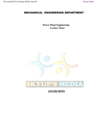
2000 oC. The ordinary engine is made of cast iron and heavy duty engines are made of steelalloys or aluminum alloys. In the multi-cylinder engine, the cylinders are cast in one blockknown as cylinder block.Cylinder head: The top end of the cylinder is covered by cylinder head over which inlet andexhaust valve, spark plug or injectors are mounted. A copper or asbestos gasket is providedbetween the engine cylinder and cylinder head to make an air tight joint.Piston: Transmit the force exerted by the burning of charge to the connecting rod. Usuallymade of aluminium alloy which has good heat conducting property and greater strength athigher temperature.Figure 1 shows the different components of IC engine.Fig. 1. Different parts of IC enginePiston rings: These are housed in the circumferential grooves provided on the outer surfaceof the piston and made of steel alloys which retain elastic properties even at high temperature.2 types of rings- compression and oil rings. Compression ring is upper ring of the pistonwhich provides air tight seal to prevent leakage of the burnt gases into the lower portion. Oilring is lower ring which provides effective seal to prevent leakage of the oil into the enginecylinder.Connecting rod: It converts reciprocating motion of the piston into circular motion of thecrank shaft, in the working stroke. The smaller end of the connecting rod is connected withthe piston by gudgeon pin and bigger end of the connecting rod is connected with the crank
with crank pin. The special steel alloys or aluminium alloys are used for the manufacture ofconnecting rod.Crankshaft: It converts the reciprocating motion of the piston into the rotary motion with thehelp of connecting rod. The special steel alloys are used for the manufacturing of thecrankshaft. It consists of eccentric portion called crank.Crank case: It houses cylinder and crankshaft of the IC engine and also serves as sump forthe lubricating oil.Flywheel: It is big wheel mounted on the crankshaft, whose function is to maintain its speedconstant. It is done by storing excess energy during the power stroke, which is returnedduring other stroke.Terminology used in IC engine:1. Cylinder bore (D): The nominal inner diameter of the working cylinder.2. Piston area (A): The area of circle of diameter equal to the cylinder bore.3. Stroke (L): The nominal distance through which a working piston moves between twosuccessive reversals of its direction of motion.4. Dead centre: The position of the working piston and the moving parts which aremechanically connected to it at the moment when the direction of the piston motion isreversed (at either end point of the stroke).(a) Bottom dead centre (BDC): Dead centre when the piston is nearest to the crankshaft.(b) Top dead centre (TDC): Dead centre when the position is farthest from the crankshaft.5. Displacement volume or swept volume (Vs): The nominal volume generated by theworking piston when travelling from the one dead centre to next one and given as,Vs A L6. Clearance volume (Vc): the nominal volume of the space on the combustion side of thepiston at the top dead centre.7. Cylinder volume (V): Total volume of the cylinder.V Vs Vc8. Compression ratio (r):Four stroke engine:-Cycle of operation completed in four strokes of the piston or two revolution of thepiston.
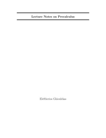
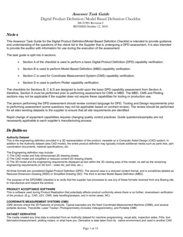
(i)(ii)(iii)(iv)Suction stroke (suction valve open, exhaust valve closed)-charge consisting offresh air mixed with the fuel is drawn into the cylinder due to the vacuum pressurecreated by the movement of the piston from TDC to BDC.Compression stroke (both valves closed)-fresh charge is compressed intoclearance volume by the return stroke of the piston and ignited by the spark forcombustion. Hence pressure and temperature is increased due to the combustionof fuelExpansion stroke (both valves closed)-high pressure of the burnt gases force thepiston towards BDC and hence power is obtained at the crankshaft.Exhaust stroke (exhaust valve open, suction valve closed)- burned gases expel outdue to the movement of piston from BDC to TDC.Figure 2 show the cycle of operation of four stroke engine.Fig. 2. Cycle of operation in four stroke engineTwo stroke engine:-No piston stroke for suction and exhaust operations-Suction is accomplished by air compressed in crankcase or by a blower-Induction of compressed air removes the products of combustion through exhaust ports-Transfer port is there to supply the fresh charge into combustion chamberFigure 3 represents operation of two stroke engine
Fig. 3. Cycle of operation in two stroke engineComparison of Four-stroke and two-stroke engine:Two-stroke engineTwo stroke of the piston and onerevolution of crankshaft2.One power stroke in each revolution ofcrankshaft3.Lighter flywheel due to more uniformturning movement4.Theoretically power produce is twicethan the four stroke engine for same size5. Heavy and bulkyLight and compact6. Lesser cooling and lubrication requirements Greatercoolingandlubricationrequirements7. Lesser rate of wear and tearHigher rate of wear and tear8. Contains valve and valve mechanismContains ports arrangement9. Higher initial costCheaper initial cost10. Volumetric efficiency is more due to greater Volumetric efficiency less due to lessertime of inductiontime of induction11. Thermal efficiency is high and also part load Thermal efficiency is low, part loadefficiency betterefficiency lesser12. It is used where efficiency is important.It is used where low cost, compactnessand light weight are important.Ex-cars, buses, trucks, tractors, industrial Ex-lawn mowers, scooters, motor cycles,engines, aero planes, power generation etc.mopeds, propulsion ship etc.1.Four-stroke engineFour stroke of the piston and two revolutionof crankshaftOne power stroke in every two revolution ofcrankshaftHeavier flywheel due to non-uniformturning movementPower produce is less
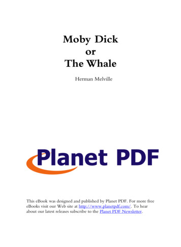
Comparison of SI and CI engine:SI engineWorking cycle is Otto cycle.Petrol or gasoline or high octane fuel isused.High self-ignition temperature.Fuel and air introduced as a gaseous mixturein the suction stroke.CI engineWorking cycle is diesel cycle.Diesel or high cetane fuel is used.Low self-ignition temperature.Fuel is injected directly into the combustionchamber at high pressure at the end ofcompression stroke.Carburettor used to provide the mixture. Injector and high pressure pump used toThrottle controls the quantity of mixture supply of fuel. Quantity of fuel regulated inintroduced.pump.Use of spark plug for ignition systemSelf-ignition by the compression of air whichincreased the temperature required forcombustionCompression ratio is 6 to 10.5Compression ratio is 14 to 22Higher maximum RPM due to lower weight Lower maximum RPMMaximum efficiency lower due to lower Higher maximum efficiency due to highercompression ratiocompression ratioLighterHeavier due to higher pressuresValve timing diagram:The exact moment at which the inlet and outlet valve opens and closes with reference to theposition of the piston and crank shown diagrammatically is known as valve timing diagram.It is expressed in terms of degree crank angle. The theoretical valve timing diagram is shownin Fig. 4.Fig. 4. Theoretical valve timing diagramBut actual valve timing diagram is different from theoretical due to two factors-mechanicaland dynamic factors. Figure 4 shows the actual valve timing diagram for four stroke lowspeed or high speed engine.
Opening and closing of inlet valve-Inlet valve opens 12 to 30ᵒ CA before TDC to facilitate silent operation of the engine underhigh speed. It increases the volumetric efficiency.-Inlet valve closes 10-60ᵒ CA after TDC due to inertia movement of fresh charge intocylinder i.e. ram effect.Figure 5 represents the actual valve timing diagram for low and high speed engine.Fig. 5. Actual valve timing diagram for low and high speed engineOpening and closing of exhaust valveExhaust valve opens 25 to 55ᵒ CA before BDC to reduce the work required to expel out theburnt gases from the cylinder. At the end of expansion stroke, the pressure inside the chamberis high, hence work to expel out the gases increases.Exhaust valve closes 10 to 30ᵒ CA after TDC to avoid the compression of burnt gases in nextcycle. Kinetic energy of the burnt gas can assist maximum exhausting of the gas. It alsoincreases the volumetric efficiency.Note: For low and high speed engine, the lower and upper values are usedrespectivelyValve overlapDuring this time both the intake and exhaust valves are open. The intake valve is openedbefore the exhaust gases have completely left the cylinder, and their considerable velocityassists in drawing in the fresh charge. Engine designers aim to close the exhaust valve just asthe fresh charge from the intake valve reaches it, to prevent either loss of fresh charge orunscavenged exhaust gas.
Port timing diagram:-Drawn for 2-stroke engine-No valve arrangement-3 ports- inlet, transfer and exhaustFigure 6 shows port timing diagram for 2-stroke engineFig. 6. Port timing diagram for 2-stroke engineWorking cycle:(a) Otto cycle- thermodynamic cycle for SI/petrol engine-Reversible adiabatic compression and expansion process-Constant volume heat addition (combustion) and heat rejection process (exhaust)Figure 7 depicts the Otto cycleFig. 7. Otto cycleHeat supplied, qs Cv(T3-T2)Heat rejection, qR Cv(T4-T1)Compression ratio,Thermal efficiency, ()(())
In process 1-2, adiabatic compression process,( )( )In adiabatic expansion process, i.e. 3-4,( )( )( )( )(( ))Work done (W)Pressure ratio, ( )( )[()()][()()][ ()()([()])]Mean effective pressure,[()()][(()()()])(b) Diesel cycle- thermodynamic cycle for low speed CI/diesel engine-Reversible adiabatic compression and expansion process-Constant pressure heat addition (combustion) and heat rejection process (exhaust)Figure 8 depicts the diesel cycle.
Fig. 8. Diesel cycleHeat supplied, Q1 Cp(T3-T2)Heat rejection, Q2 Cv(T4-T1)Compression ratio, Cut off ratio, (Thermal efficiency,)(())()()In adiabatic compression process i.e. 1-2,( )( )In process 2-3, pressure constant, then( )In adiabatic expansion process i.e. 3-4,( )( ( ))( )((() ))()( )( )[( )( )()]Work done (W)()()*()(*since) (()) (() )
Mean effective pressure,[()()][ ()(()()])(c) Dual cycle or limited pressure cycle-thermodynamic cycle for high speed dieseland hot spot ignition engine-Reversible adiabatic compression and expansion process-Constant pressure and constant volume heat addition (combustion) and heatrejectionprocessTotal heat supplied, Q1 Cv(T3-T2) Cp(T4-T3)Heat rejection, Q2 Cv(T5-T1)Compression ratio, Cut off ratio, Pressure ratio, Figure 9 shows the P-V diagram of Dual cycle.Fig. 9. Dual cycle(Thermal efficiency,()()(In adiabatic compression process i.e. 1-2,( ))(( )In constant volume combustion process i.e. 2-3,)())(())
In constant pressure combustion process i.e. 3-4,In adiabatic expansion process i.e. 4-5,( )( )( )( )(())(()( )[())]()Work done (W)()()[()(())()()])()()]Mean effective pressure,[[ (() (())(()Comparison of Otto, Diesel and Dual cycle:(a) For same compression ratio and same heat input()()()(b) For constant maximum pressure and same heat input)]
()()()(c) For same maximum pressure and temperature()()()(d) For same maximum pressure and output()()FUELS &FUEL INJECTIONIn IC engines, the chemical energy contained in the fuel is converted into mechanical powerby burning (oxidizing) the fuel inside the combustion chamber of the engine.Fuels suitable for fast chemical reaction have to be used in IC engines, they are followingtypes(a) Hydrocarbons fuels derived from the crude petroleum by proper refining process such asthermal and catalytic cracking method, polymerisation, alkylation, isomerisation, reformingand blending.(b) Alternative fuels such as-Alcohols (methanol, ethanol)Natural gas (methane)LPG (propane, butane)Hydrogen*Classification of petroleum fuels used for IC engine:Liquid hydrocarbons- Engine fuels are mainly mixtures of hydrocarbons, with bondsbetween hydrogen and carbon atoms. During combustion these bonds are broken and newbonds are formed with oxygen atoms, accompanied by the release of chemical energy.Principal products are carbon dioxide and water vapour. Fuels also contain small amounts ofS, O2, N2, H2O. The different constituents of crude petroleum which are available in liquidhydrocarbons are- paraffins, naphthenes, naphthenes, olefins, aromatics.(i) Paraffin-Paraffins or alkanes can in general be represented by-CnH2n 2-All the carbon bonds are single bonds – they are “saturated” high number of H atoms, highheat content and low density (620 – 770 kg/m3)-The carbon atoms can be arranged as a straight chain or as branched chain compounds.-Straight chain group (normal paraffins) shorter the chain, stronger the bond not suitable for SI engines – high tendancy for autoignition according to the value of“n” in the formula, they are in gaseous (1 to 4), liquid (5 to 15) or solid ( 16) state.
-Hexan C6H14 (normal paraffin)H H H H H HH–C–C–C–C–C–C–HH H H H H H- Branched chain compounds (isoparaffins)When four or more C atoms are in a chain molecule it is possible to form isomers,they have the same chemical formula but different structures, which often leads tovery different chemical properties.Example: Iso-octane- C8H18(ii) Naphthenes-Also called as cycloparaffins and represented as CnH2n-Saturated hydrocarbons which are arranged in a circle have stable structure and lowtendancy to autoignite compared to alkanes (normal paraffins)-Can be used both in SI-engines and CI-engines-Low heat content and high density (740 – 790 kg / m3)(iii) Olefins-Olefins or alkenes are represented as Mono olefins-CnH2n or Dio-olefins CnH2n-2-Olefins have the same C-to-H ratio and the same general formula as naphthenes, theirbehavior and characteristics are entirely different-They are straight or branch chain compounds with one or more double bond. The position ofthe double bond is indicated by the number of first C atom to which it is attached, i.e.,CH2 CH.CH2.CH2.CH3 called pentene-1CH3.CH CH3 called butene-2-Olefinic compounds are easily oxidized, have poor oxidation stability-Can be used in SI-engines, obtained by cracking of large molecules low heat content anddensity in the range 620 – 820 kg / m3Alkenes are such as,Hexen (mono-olefin)H H H H H HH–C–C–C–C–C C-HH H H HButadien (dio-olefin)H H H HH–C C–C C–H(iv) Aromatics-These are so called due to aromatics odour and represented as CnH2n-6-They are based on a six-membered ring having three conjugated double bonds-Aromatic rings can be fused together to give polynuclear aromatics, PAN, also calledpolycyclic aromatic hydrocarbons, PAH simplest member is benzene (C6H6)
-Can be used in SI-engines, to increase the resistance to knock not suitable for CI-engines dueto low cetene number-Low heat content and high density in the range 800 – 850 kg / m3*Refinery processes:Crude oil is the liquid part of the naturally occurring organic material composed mostly ofHCs that is trapped geologically in underground reservoirs – it is not uniform and varies indensity, chemical composition, boiling range etc. for different fields. The refinery processesinvolved in production of different range of fuel is shown in Fig. 10 and Fig. 11.Fig. 10. Refinery processesFig. 11. Products made from crude oil(i) Distillation process-This is the initial process used in all refineries – aims to separate the crude oil into differentboiling range fractions, each of which may be a product in its own right, a blend componentor feed for further processing step-Crude oil contains many thousands of different HCs, each has its own boiling point – lightestare gases at ambient temperature but can remain dissolved in heavier liquid HCs unless
temperature is raised, heaviest are solids at ambient temperature but stay in solution unlesstemperature is lowered.Gasoline distillation temperature is 35 – 200 oCJet fuel 35 - 150Diesel fuel 175 – 370Heavy fuels, oil 370 – 550-Generally distillation of crude oil produces 30% gasoline, 20-40 % diesel fuel, 20 % heavyfuels, 10-20 % heavy oils.(ii) Cracking process-There are two types of cracking process for engine fuel production: thermal cracking andcatalytic cracking(a)Thermal cracking: It takes place through the creation of HC free radicals by Cto- C bond scission-The feed is heated to around 500 - 600 OC and 70 - 100 bars and passed into asoaking chamber where cracking takes place. The cracked products are fractionated.The product is relatively unstable and requires the use of antioxidants and othertreatments to prevent gum formation in use. It has relatively poor MON (motor octanenumber).(b)Catalytic cracking: It is the most important and widely used process forconverting heavy refinery streams to lighter products – to increase the ratio of light toheavy products from crude oil.-Compared to thermal cracking, it has higher yield, improved quality product forgasoline (not for diesel fuel) and superior economics.-A fluidized bed of catalyst is used – feed is introduced into it. Catalyst flows fromone vessel to another through a pipe (between reactor and regenerator). Cracked oilvapour pass to fractionating towers where smaller molecules are separated fromheavier products (gas, catalytic naphtha, cycle oils and residue).-Aluminium silicate known as zeolite is used as a catalyst – has high activity andsuppress the formation of light olefins.(iii)Alkylation: It is a process for producing a high-octane gasoline component (alkylate) bycombining light olefins with isobutane in the presence of a strongly acidic catalyst (sulfuricor hydrofluoric acid).(iv)Isomerization: It is a process for converting straight chain paraffins to branch chain –used to provide isobutane feed for the alkylation process or to convert relatively low-octanequality of straight paraffins to more valuable branch chain molecules.eg. n-pentane with RON (research octane number) 62 can be converted to isopentane withRON 92-Process involves contacting HCs with a catalyst (platinum on a zeolite base) and separatingany unchanged straight paraffins for recycle through the unit. The product is clean burningand has better RON quality.
(v)Polymerization: It is a process where light olefins such as propene and butenes are reactedtogether to give heavier olefins which have good octane quality and low vapour pressure ingasoline.-Most commonly used catalyst is phosphoric acid-The product is almost 100 % olefinic and has relatively poor MON compared with RON.eg. CH3CH2CH CH2 CH3CH CH2 CH3(CH2)4CH CH2butenepropeneheptene*Alternative fuels:(a) Alcohols: These include methanol (methyl alcohol), ethanol (ethyl alcohol), propanol(propyl alcohol), butanol (butyl alcohol) as compounds-The OH group which replaces one of the H atoms in an alkane, gives thes
LECTURE NOTES ON SUB: INTERNAL COMBUSTION ENGINE & GAS TURBINES 8th SEMESTER, B.TECH MECHANICAL ENGINEERING COURSE CODE – BME 423 Prepared by: Mrs. Dulari Hansdah