Transcription
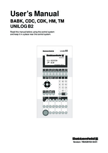
User’s ManualBABK, CDC, CDK, HM, TMUNILOG B2Read this manual before using the control systemand keep it in a place near the control system.Version: TB2GBV02 03/01
Injection Moulding TechnologyBattenfeld GmbHScherl 10 D-58527 MeinerzhagenTel. 49 2354/72-0 Fax 49 2354/72-234TB2GBD2B.P65Battenfeld Kunststoffmaschinen Ges.m.b.H.Wr.Neustädter Straße 81 A - 2542 KottingbrunnTel. 43 2252/404-0 Fax 43 2252/404-261www.battenfeld.comDIN EN ISO 9001
Caution! Caution! Caution! Caution!Important information for commissioning!For commissioning and operating the machine, passwords have beenassigned ex works.These passwords enable the operator of the machine or the person adjustingthe machine to carry out the initial operation procedure.Customer password: 1998Customer service password: 1990For information on the handling of the password protection please refer to the"The Control Unit UNILOG B2" chapter in the control unit’s manual.To prevent the machine from interventions by non-authorised persons, theuser should remove this page from the operating manual and keep it in a safeplace.A: TB2GBPAA.P65B: TB2DEPAA.P65E: 130900 / D. SchwabG: 230301 / Ruder
Index0Preface4Injection unitSettingsThe Control Unit UNILOGB2Control elementsNozzle contact5KeyboardInjectionInjection profileKey functionsPre-extrusionDisplayHandling of the control unit6Holding pressureOperation errorHolding pressure profileErrorsCooling timePassword protection71Machine in generalSettings Metering /DecompressionPasswordBack pressureInformationProgram preselections28Open / Ejector / Air valvesToggleTemperature control zonesChange over timeScrew barrelSettings EjectorTolerancesAir valves (option)Mould temperaturesStart-up / DecreaseMetering / Decompression9Control optimisationCore pullers (option)Settings Core pullersFeed zone / Tolerances103CloseMould safety deviceQuality tableEvaluationConfigurationHigh pressureMould mounting heightA: TB2GBI3B.P65B: TB2DEI3B.P65E: 241100 / T. WeißG: 230301 / RuderChapter - IPage - 1
Index11Monitoring15Robot interfaceParts counterRobot interfaceTime monitoringLC RobotWeekly time switchParts removal robotCalendar clock1712ServiceLoadSetting parametersSaveStroke calibration13Machine overviewData record managementDelete19Cycle overviewPrintSelectionMachine parametersStartInputs / outputsLanguageAxis statusController status20Error messagesSymbols14PeripheryInterrupt listMaterial conveyorAirmouldBelt conveyorChapter - IPage - 2A: TB2GBI3B.P65B: TB2DEI3B.P65E: 241100 / T. WeißG: 230301 / Ruder
The Control Unit UNILOG B2PrefaceWho is this manual intended for?This manual is intended for all persons who areto operate and to monitor the injection mouldingmachine.Your task is to monitor the proper functioning ofthe machine. In case a malfunction occurs, youshould be able to retrieve information as to thecause of malfunction as well as the essentialmachine data. To this end, you must be familiarwith the operation of the control unit. Thismanual provides the knowledge by means ofwhich you may safely operate the control unit.What are the contents of this manual?Usage to the intended purposeThe control system UNILOG B2 is designed forthe operation and control of injection mouldingmachines.The operation of the control unit is reserved fortrained personnel only (e.g. tool setters, servicetechnicians). Other usage is not permitted.Safety measuresThis manual is part of the technicaldocumentation on the injection mouldingmachine. Before operating the control system,make sure you are familiar with all the safetymeasures required for the operation of theinjection moulding machine.To keep this manual as short and as accessibleas possible, only those operations are describedwhich you can/ are permitted to carry outyourself. Functions and information relating tocommissioning and special service measuresare compiled in a separate service manual onlyavailable to those members of the Battenfeldstaff who have been specially trained for thiskind of work.At first, an overview on the control elements ofthe control system will be provided. An exampleof the typical operational procedure will be given,followed by a detailed description of theindividual display menus.As a rule, the description will always follow thesame pattern: After a short introduction to therespective function, the individual parameterswill be described in detail.A: TB2GB00B.P65B: TB2DE00B.P65E: 091000 / D. SchwabG: 230301 / RuderChapter - 0Page - 1
The Control Unit UNILOG B2The Control Unit UNILOG B2Function overviewThe digital control unit UNILOG B2 has beendeveloped from the control unit UNILOG 2040.All functions of the injection moulding machinemay be controlled via the display menus and thekeyboard. The functions are classified accordingto the subassemblies or the respectiveactivities. To select a menu, you simply have topress the appropriate key. The symbols facilitatea quick access to the desired function.For the manual operation, the machinesdisposes of 8 given keys operating the mainfunctions of the machine (drive, heating, andoperating mode). Another 16 keys are assignedother functions, depending on the machine type(e.g. opening / closing the mould).The control system comes with a dust-proofeasy to clean membrane keyboard. Whenpressing a key, you can feel a distinct actionpoint which thus improves safety during input.Chapter - 0Page - 2A: TB2GB00B.P65B: TB2DE00B.P65E: 091000 / D. SchwabG: 230301 / Ruder
The Control Unit UNILOG B2Control elements1Display7Control system type2Function keys with graphic symbolsDirect selection of a menu8Numeric keysInput of values3Cursor keysMovements within the menus9"ENTER" keyAcceptance of input values4"Back" keyPage up within the menus10"C" key (Clear)Deletes entries5Other function keys with graphicsymbolsInformation and data management11Function keysMain functions12Function keysManual mode: assignment dependingon the machine6"EMERGENCY STOP" keyA: TB2GB00B.P65B: TB2DE00B.P65E: 091000 / D. SchwabG: 230301 / RuderChapter - 0Page - 3
The Control Unit UNILOG B2KeyboardNumeric keysThe control unit has several keypads.The numeric keys in the numerical keypad aredesigned for the input of numeric values.Function keys with graphic symbols"C" key (Clear)The function keys below the display aredesigned for the direct selection of a menu. Thegraphic symbols represent the functionscompiled in the respective menu.Press the "C" (Clear) key to delete an entry andthe "ENTER" key to accept it.In case a menu consists of several pages, scrollto the next page by depressing the samefunction key several times. If you want to pagedown, hold down the "Back" key in the middle ofthe cursor keys and press the respectivefunction key afterwards.The function keys below the cursor keys aredesigned for data management and for viewingthe alarm messages. You may save and loaddata and have them printed.Cursor keysUse the cursor keys arranged on the circle toselect the individual fields of the display menu.The selected field will be presented reversely.You may only enter data in a selected andhighlighted field. Always press the "ENTER" keyto acknowledge the entries."Back" keyOther function keys with graphic symbolsThe lower function keys are used for the directcontrol of the machine. The keys in the first rowoperate the main functions of the machine. Twoor three keys cooperate like two-way switches.A light emitting diode integrated within the keysignals the current switch position.Depending on the machine type, the keys in thelast two rows are assigned further functions.The integrated light emitting diodes signal thelimit position of the respective function.Use the "Back" key to page up the last 10menus selected in reversed order.Chapter - 0Page - 4A: TB2GB00B.P65B: TB2DE00B.P65E: 091000 / D. SchwabG: 230301 / Ruder
The Control Unit UNILOG B2Key functionsMonitoring functions F11Machine in general F01Service C12Temperature control zones F02Machine overview F13Close F03Periphery F14Injection unit F04Robot F15Injection F05Reserve F16Holding pressure F06Data record management F17Metering, Decompression F07Not assigned F18Open / Ejector / Air valves F08Print F19Core pullers F09Error messages F20Quality table F10A: TB2GB00B.P65B: TB2DE00B.P65E: 091000 / D. SchwabG: 230301 / RuderChapter - 0Page - 5
The Control Unit UNILOG B2"Back" keyNumeric keys 0.9.Point, minus"Clear" key (delete)"ENTER" key (accept input)Drive Stop (red LED)Drive Start (green LED)Drive StopThe red LED will be lit up if the drive has beenswitched off manually (using the "Stop" key).The red LED will flash if the drive has beenswitched off using either a monitoring programor the weekly time switch.Drive StartThe green LED will flash if the drive is in thestart-up phase and will be lit up if the drive runs.The green LED is lit up when the oil heatingstarts or the drive is ready for operation.Manual modeAutomatic modeSetting modeHeater off (red LED)Heater on (green LED)Decrease temperature inheater (green LED)Use the keys for the heating to activate thebarrel heating, mould heating (option) and theheaters (option) activated.NoteThe mould heating and the heaters have to beactivated in the respective displays (see chapter2).Heater offThe red LED will be lit up if the heater has beenswitched off manually (using the "Heater off"key).The red LED will flash, if the heater has beenswitched off using either a monitoring programor the weekly time switch.Heater onThe green LED will be lit up if the heater isswitched on.Decrease temperature in heaterThe green LED is lit up if the temperature in theheater is either decreased manually or by usinga monitoring program.The green LED flashes during the Delay timeTemperature decrease until the temperaturedecrease is activated.The activated operating mode will be indicatedby the green LED.Chapter - 0Page - 6A: TB2GB00B.P65B: TB2DE00B.P65E: 091000 / D. SchwabG: 230301 / Ruder
The Control Unit UNILOG B2Open mouldClose mouldOptions12Ejector forwardEjector backwardAir valve 1Air valve 2In the manual mode, the air valvesare activated by pressing thefunction key.Material conveyorOn / OffInjection unit forwardInjection unit backUse this function key to switch thematerial conveyor on or off.Injection and holding pressureMetering / DecompressionReduce / increase mouldmounting height (togglemachines only)ROBOTLC RobotBackward / forwardAll movements of the "Unipick P5"LC robot are performed forwardand backward, depending on the programsetting.ROBOTParts removal robotForward / Backward ClockingAll movements of the parts removalrobot will be carried out accordingto the program setting by pressing the rightfunction key. Use the left function key to moveback single movements of the parts removalrobot to the initial position.A: TB2GB00B.P65B: TB2DE00B.P65E: 091000 / D. SchwabG: 230301 / RuderChapter - 0Page - 7
The Control Unit UNILOG B2Move in core pullerMove out core puller10In the manual and the setting mode,these function keys on the operatorpanel are used to perform the movement.Key-operated switchManual mode / Automatic modeTo prevent the machine from beingchanged over by unauthorisedpersons, the Manual mode /Automatic mode selection switchhas been designed as key-operated switch.The key can be removed in any position.NoteThe Manual mode / Automatic mode functionkeys will then be assigned no function. Only thesetting mode can be selected.01231231231231231Chapter - 0Page - 81Key-operated switch /Acknowledgement keyManual moulded article removalThis option enables the operator toremove the injection mouldingmanually. To this end, the safetygate will already be opened duringthe core puller or the ejectormovement (when opening themould) (TM, HM machines).Key-operated switch versionThe function can be switched on or off using thekey-operated switch. The key can be removed inany position.Acknowledgment key versionKey-operated switchAlarm horn On / OffThe function is generally active. Theacknowledgement key is designed to enable thecore puller or the ejector movement.Use this key-operated switch (CDConly) to switch off the function ofthe alarm horn. The key can beremoved in any position.CautionIf the acknowledgment key has been pressedduring the closing movement, an error messagewill occur.A: TB2GB00B.P65B: TB2DE00B.P65E: 091000 / D. SchwabG: 230301 / Ruder
The Control Unit UNILOG B2DisplayVia the menus shown on the display, you mayobtain all the information required for theoperation of the machine.At the lower edge of the display, the symbol ofthe selected function is shown on your left. Tofacilitate the orientation, the function is markedby a function number, e.g. F03. The number ofpages contained in this menu as well as thecurrent page (e.g. 1/2 page 1 of 2 pages) areindicated below.The field on the outer right of the lower edge isexclusively reserved for the malfunctionindication. In case of an error, the flashing errorsymbol will be displayed within this field. On theleft of the symbol, you can see the time set inthe system. This time indication always has tocorrespond to the actual time to ensure thatcontrol functions are carried out properly.A: TB2GB00B.P65B: TB2DE00B.P65E: 091000 / D. SchwabG: 230301 / RuderIn the main part of the display, the set and theactual values together with the selectedfunctions are displayed within different fields. Ingeneral, the values are displayed in SI units, theparameters are assigned English orinternational abbreviations.Brightness settingYou can use the keyboard to change thebrightness of the LC display. To this end, pressthe "Back" key and one of the "Cursor" keyssimultaneously. The settings will be savedautomatically.Set the brightness lower: "Back Up Arrow"Set the brightness higher: "Back Down Arrow"Chapter - 0Page - 9
The Control Unit UNILOG B2Handling of the control unit Enter the other set values in the samewayIn the following, an example shows you how youwork with the control system.Example: Setting the temperature control zonesF02 26 01DE.BMP Press the "Temperature control zones"key. The first page (1/6) of the F02 menuwill be displayed Press the "Temperature control zones"key. The second page (2/6) of the F02menu will be displayed. The input fieldfor the upper set tolerance value isselected (L ) Enter the desired tolerance value usingthe numeric keys Press the "C" key in case you haveentered an incorrect set value. Theentered set value will be deleted Enter the new set value using thenumeric keys Press the "ENTER" key. The set valuewill be accepted Enter the lower tolerance value in (L-) inthe same way Hold down the "Back" key and press the"Temperature control zone" key. The firstpage (1/6) of the "F02" menu will bedisplayed againF02 16 01DE.BMP When the page is displayed, the firstfield in the upper left will always beselected for set value input. (T0 Temperature control zone 0) Enter the desired set temperature valueusing the "numeric keys" Press the "ENTER" key. The set valuewill be accepted Press the cursor keys until the next fieldis selected for the set value input (T1) Enter the set value via the numeric keysonce again and press the "ENTER" keyto accept the inputChapter - 0Page - 10A: TB2GB00B.P65B: TB2DE00B.P65E: 091000 / D. SchwabG: 230301 / Ruder
The Control Unit UNILOG B2What happens in case of amaloperation?ErrorsIn case an error occurs at the machine, theerror symbol on the display will be flashing.Information on the incoming error may beretrieved immediately.F03 21 01DE.BMPThe entire input will be entered in the selectedfield. When pressing the "ENTER" key, thecontrol system only accepts those values whichare valid, i.e. those being within the allowedvalue range or containing correct characters. Incase the entered value is invalid, the originalvalue will be displayed in the input field afterpressing the "ENTER" key. For your information,the permitted limiting value of the respectiveparameter is displayed next to the functionsymbol at the lower edge of the display. Youmay now repeat the input, using a valid value.F03 31a 01DE.BMPF20 13a 01DE.BMP Press the "Error messages" key. TheF20 menu will be overlain. One orseveral incoming errors will berepresented as symbols Press the "Error messages" key severaltimes to scroll down all pages, ifappropriateIf you are not able to remedy the cause of erroryourself, call a service technician, stating thealarm message currently represented assymbol. On the third page of the menu, youobtain additional information on the incomingerrors, if necessary. Note the additionalinformation and have them ready for inquiries.NoteA detailed description of the error messagesmay be found in the "Error messages F20"chapter in this manual.A: TB2GB00B.P65B: TB2DE00B.P65E: 091000 / D. SchwabG: 230301 / RuderChapter - 0Page - 11
The Control Unit UNILOG B2Password protectionThe access to the control system is protectedon several levels by means of a password.If no password has been entered, all usermenus may be selected; however, the input ofset values is not possible.After entering the customer password, all usermenus may be selected and the set values maybe entered.In addition to the user menus, the customerpages of the " Service C12" menu may also beaccessed after entering the customer servicepassword.In addition to the user menus, all service menupages will also be accessible after entering theservice password. The service password is onlyavailable to members of the Battenfeld staff.In order to disable the access after entering thepassword, the input of an incorrect passwordwill be sufficient, e.g. 0.NoteFor further information on the password entry,please refer to chapter "Machine in generalF01".Chapter - 0Page - 12A: TB2GB00B.P65B: TB2DE00B.P65E: 091000 / D. SchwabG: 230301 / Ruder
Machine in general F01Machine in general F01Three screen pages are available in the presentmenu. Page 1 is the start page which willalways be displayed after starting up the controlunit. On page 2/3 you can find a legend on howto handle the control unit and on page 3/3, avariety of program selections can be made.Password system F01 1/3N1 Select field "N1". Enter an invalid password (e.g. 0) andpress the "ENTER" key. The input of setvalues is no longer possibleN2Character set0Latin1ChineseIf required, you can change over the charactersused to identify the functions and parameters inthe menus. Either Latin or Chinese characterswill be used.PasswordF01 13 01DE.BMPAfter entering the correct password, the setvalues may be entered. Without a password,you may select all user menus and view data,but you are not allowed to change them. Themenu for the entry of the password will beautomatically displayed when switching on themachine.Enter the password Select field "N1". Enter the password and press the"ENTER" key. The set values can nowbe enteredA: TB2GB01B.P65B: TB2DE01B.P65E: 161100 / D. SchwabG: 230301 / RuderDisable set value input Select field "N2". Enter either 0 for Latin or 1 for Chinesecharacters and press the "ENTER" key.The menus will now be displayed in theselected languageUnit system:metricspiThe settings for the units can be seen on thelower edge of the page. The software enables achange over between metric and SPI units (USunits).Chapter - 1Page - 1
Machine in general F01LegendInformation F01 2/3p - pressurePressure [bar] / [psi]t - timeTime [s / min]v - speedSpeed [%]T - temp.Temperature [ C] / [ F]F01 23 01DE.BMPOn this page, an overview on the symbols andabbreviations predominantly used in the menuswill be given. On the right, the current version ofthe visualisation master will be displayed.C - counterCounter [pieces]W - watchCycle time [s / min]L - limitTemperature tolerance [ C] / [ F]Fields for set value inputs (pointed)Field for program selection (arrow)P - performanceHeating capacity [%]s - strokeStroke [mm] / [inch]N - programProgramField for actual value display (square)Chapter - 1Page - 2actual valuesActual valuesA: TB2GB01B.P65B: TB2DE01B.P65E: 161100 / D. SchwabG: 230301 / Ruder
Machine in general F01Program preselections F01 3/31Semiautomatic mode 1If the "Semiautomatic mode 1" program isswitched on, only one of the machine cycles willbe completed automatically. The "Automatic" keyhas to be pressed (LED on). The user must nowopen the safety gate, discharge the injectionmoulding and close the safety gate again. Tostart a new cycle press the "Close" or the "Closesafety gate" key (option, up to size 2700 / -).F01 33 01DE.BMPYou may select and activate different programsfor the machine operation.Automatic operating mode0Fully automatic mode21Semiautomatic mode 12Semiautomatic mode 2The program "Semiautomatic mode 2" enablesthe user to discharge the injection moulding fromthe machine themselves. If the program isswitched on, the cycle is carried outautomatically up to the "Ejector front" strokeposition. The "Automatic" key has to be pressed(LED on). The user must now open the safetygate, discharge the injection moulding and closethe safety gate again.Select one of the operating modes for theautomatic mode.0Fully automatic modeIf the "Fully automatic mode" program has beenswitched on, the machine will be operated in thefully automatic mode. The "Automatic" key hasto be pressed (LED on). Press the "Close" keyto start the first cycle.A: TB2GB01B.P65B: TB2DE01B.P65E: 161100 / D. SchwabG: 230301 / RuderCautionWhen removing the moulded articles manually(option), "Open mould" (TM / HM only), "Ejectorforward and back", and "Move core puller in andout" can also be performed with the safety gateopened, the key-operated switch activated or theacknowledgement key held down.Semiautomatic mode 2NoteIt is recommended to choose the stroke marker"Ejector front" so that the injection moulding isjust prevented from falling down and may easilybe discharged while the safety gate is opened.Chapter - 1Page - 3
Machine in general F01To start a new cycle press the "Close" or the"Close safety gate" key (option, up to size2700 / -,-). The cycle starts with the ejectormoving backward.CautionWhen removing the moulded articles manually(option), "Open mould" (TM / HM only), "Ejectorforward and back", and "Move core puller in andout" can also be performed with the safety gateopened, the key-operated switch activated or theacknowledgement key held down.Motor Stop Heater Stop0off1onIn case this program is switched on, the heaterwill also be switched off, if the drive motor hasbeen switched off. This program may used asan alternative to "N3" - "Motor Stop andTemperature decrease".The operating steps in detail:Motor Stop Temperaturedecrease Close safety gate0off Press "Close" or "Safety gate Close"(option; up to size 2700 / -). The cyclestarts1on Open the safety gate after reaching"Ejector front" stroke marker Discharge injection moulding Close safety gate Press "Close" or "Safety gate Close"(option; up to size 2700 / -) The nextcycle startsChapter - 1Page - 4If the present program is switched on, theheating will be decreased to the "loweredtemperature" if the drive motor is switched off("Temperature control zones F02" menu, page2/6, parameter "N3").If the drive motor is switched on again, theordinary temperature settings are valid.A: TB2GB01B.P65B: TB2DE01B.P65E: 161100 / D. SchwabG: 230301 / Ruder
Machine in general F01Cycle counter switch-offDrop-out preventer (option)0off0off1on1onIn case this program is switched on, the controlunit switches the drive motor off automatically atthe end of the cycle when reaching the set"cycle number" ("Monitoring functions" menuF11, page 1/5, parameter "C2").After switching the machine to "Manual mode",the drive motor may be switched on again. To beable to run the machine in the "Automatic mode"again, either the actual value of the cyclecounter has to be reset (parameter "N7") or theset value "C2" has to be increased. Otherwisethe machine will immediately switch off at theend of the cycle.If the program is switched on, a new cycle willbe disabled until the injection moulding haspassed the photoelectric barrier. If the injectionmoulding does not pass the photoelectric barrierduring the change over time (injection mouldingwill be ejected), the next cycle will not bestarted. The control system signals an error.CautionIf the photoelectric barrier remains interruptedduring the entire cycle (e.g. if ejected partsproject into the drop-out area of the machine),the next closing procedure will also be disabled.Mould heating (option)0off1onIn addition to the barrel heating you may switchon the mould heating with its own tolerancesand lowered temperature.A: TB2GB01B.P65B: TB2DE01B.P65E: 161100 / D. SchwabG: 230301 / RuderChapter - 1Page - 5
Machine in general F01Automatic stop function forcooling water (option)0off1onIf the program is switched on, the valve for theautomatic stop function for the cooling water(mounted at the cooling water distributor) will beclosed for "Motor Stop" in the "Automatic mode".The valve is always opened in the manual modeor if the program is switched off.Central lubrication (option)0off1onUse this program to start a manual lubricationcycle, if required.The lubricating time depends on the respectivesetting on the service menu page. (Each hour 2lubrication cycles with 5 sec. each).During normal operation, the control unit willcarry out the lubricating interval automatically, inaccordance with all machine cycles selected inthe service menu.Screw change (from size - / 1900)0off1onTo change the screw, it is necessary that theinjection unit is completely back. If you haveselected the screw change program, you moveback the injection unit completely in the settingmode. To this end, it is necessary that theinjection piston is in the front position.Dry operation Clamp. unit (option)0off1onIn addition to the selected automatic mode, thefollow selection options are available. If theprogram is active only the movements of theclamping unit, the ejector, the core pullers, andthe unscrewing device will be used. Theinjection assembly will not be triggered.NoteNote that the "Breathing" or "Compression"functions must not be activated in this operatingmode. In addition, the injection assembly mustbe heated up to operating temperature.Default setting:TM 500 / -:10000TM 750 / -:6000TM 1000 / -:6000from TM 1300 / -:Chapter - 1Page - 6125A: TB2GB01B.P65B: TB2DE01B.P65E: 161100 / D. SchwabG: 230301 / Ruder
Temperature control zones F02Temperature controlzones F02Temperature control zones Screwbarrel F02 1/6This menu consists of 6 pages.On page 1/6, you may specify the set values fora maximum of 8 temperature control zones ofthe screw barrel, on page 2/6 the respectivetolerance values and the lowered temperature.On page 3/6, you may specify the set values fora maximum of 5 temperature control zones ofthe mould, on page 4/5 the respective tolerancevalues.Page 5/6 contains the parameters for the controloptimisation.On page 6/6, you can specify the set value forthe feed zone and the respective tolerancevalues.Enter the set values for the temperatures T andthe tolerances L in [ C] / [ F], the set values ofthe heating capacity "P" in [%] of the maximumcapacity, the time "t" in [min].F02 16 01DE.BMPThe set temperatures for a maximum of 8screw barrel zones may be entered and therespective actual values may be retrieved.T0 - T7Set values Temperature controlzonesEnter a set value for each used temperatureprobe of the screw barrel.CautionInactive temperature sensor inputs have to bebridged.T0 -T7 Actual values Temperature controlzonesDisplay of the current temperature of therespective temperature control zone of thescrew barrel.A: TB2GB02B.P65B: TB2DE02B.P65E: 080900 / D. SchwabG: 230301 / RuderChapter - 2Page - 1
Temperature control zones F02Tolerances / Temperaturedecrease F02 2/6L-You may specify by how many degrees theselected set value may be fallen short of. Thetolerance value is valid for all temperaturecontrol zones of the screw barrel. When fallingshort of the tolerance in the automatic mode, thecontrol system disables the functions Injection,Metering, and Decompression.T10F02 26 01DE.BMPUpper and lower tolerance values for thespecified set temperatures and the settemperature for the temperature decreaseprogram may be determined.L Upper ToleranceYou may specify by how many degrees theselected set value may be exceeded. Thetolerance value is valid for all temperaturecontrol zones of the screw barrel. Whenexceeding the tolerance in the automatic mode,the control system disables the functionsInjection, Metering, and Decompression.NoteIn the manual mode, material may be injecteddespite exceeding the tolerance.Chapter - 2Page - 2Lower ToleranceLowered temperatureEnter the set value for the lowered temperature.If the present program is switched on ("Programpreselections F01" menu, page 3/3, parameter"N3"), the heating will be decreased to the"lowered temperature" if the drive motor isswitched off.The set value for the lowered temperature isalso valid for the manual decrease of thetemperature in the heater ("Decrease heater"key).During the temperature decrease, the Injection,Metering, and Decompression functions aredisabled.P0 - 7 Actual value Heating capacityFor each temperature control zone of the screwbarrel, the current heating capacity is indicatedin per cent. If required, you may check theproper functioning of the heater by means ofthese values.A: TB2GB02B.P65B: TB2DE02B.P65E: 080900 / D. SchwabG: 230301 / Ruder
Temperature control zones F02T12Actual value Oil temperatureDisplay of the current hydraulic oil temperaturewithin the oil tank. The respective set values arepreset in the control system and cannot bechanged here.Temperature control zones MouldF02 3/6When undershooting 40 C (104 F), thehydraulic oil will be heated. While the oil is beingheated, all movements of the machine will bedisabled.When reaching 45 C (113 F), the coolingwater valve to the oil cooler opens. At 60 C(140 F), there w
Control elements 1 Display 2 Function keys with graphic symbols Direct selection of a menu 3 Cursor keys Movements within the menus 4 "Back" key Page up within the menus 5 Other function keys with graphic symbols Information and data management 6 "EMERGENCY STOP" key 7 Control system type 8