Transcription
IEEE TRANSACTIONS ON SYSTEMS, MAN, AND CYBERNETICS-PART A SYSTEMS AND HUMANS, VOL. 26, NO. 1, JANUARY 199681A Knowledge-Based Simulation Environmentfor Hierarchical Flexible ManufacturingBernard P. Zeigler, Fellow, ZEEE, Tae H. Cho, and Jer:zy W. Rozenblit, Member, IEEEAbstract- This article presents an approach to embeddingexpert systems within an object oriented simulation environment.The basic idea is to create classes of expert system modelsthat can be interfaced with other model classes. An expertsystem shell is developed within a knowledge-based design andsimulation environment which combines artificialintelligence andsystems modeling concepts. In the given framework, interruptibleand distributed expert systems can be defined as componentsof simulations models. This facilitates simulation modeling ofknowledge-based controls for flexible manufacturing and manyother autonomous intelligent systems. Moreover, the structureof a system can be specified using a recursive system entitystructure (SES) and unfolded to generate a family of hierarchicalstructures using an extension of SES pruning called recursivepruning. This recursive generation of hierarchical structures isespecially appropriate for design of multilevel flexible factories.The article illustrates the utility of the proposed frameworkwithin the flexible manufacturing context.I. INTRODUCTIONCOMPUTER simulation is one of the most widely usedtechniques in manufacturing systems study [ 11-[3].Rapid modeling of such systems can play a significant role insupporting timely determination of optimal manufacturingstrategies in response to changing market requirements.However developing simulation models of large-scale complexsystems is an arduous, time-consuming task.Simulation modeling of manufacturing and other systemshas become even more demanding due to the incorporationin recent years of intelligent knowledge-based elements intotheir control functions. For example, expert systems have beendeveloped for solving problems of varying complexities inareas such as planning, scheduling, controlling, maintenanceand fault diagnosis [3]-[7]. Such knowledge-based systemspresent a host of specific requirements on an environment toaid the simulation model builder. Such issues include:Communication Links: Expert and knowledge-based control elements have to interact efficiently with the manufacturing or other processes they control. This requires thatthere be a systematic way of establishing communicationlinks between expert system elements and other modelcomponents for rapid and valid model development.Distributed Expert Systems: Expert systems may be spatially and functionally distributed. This requires the capability to represent multiple expert system model components, often copies of the same prototypes, within thesame simulation environment.ZnterrzqtibiZity: Often, due to cost and resource limitations, only one expert system agent is available tohandle requests from multiple sources. In this case, theinferenicing has to be interrupted to process more urgentrequests first. Also inferencing may have to pause whilewaiting for needed process data. Such interruptlresumebehavior should be representable in the simulation model.Hierarchical Modular Construction: Expert systemsshould be treated no differently from other simulationmodels in building complex models from components ina model base [SI-[lo].These requirements must be satisfied in order to efficientlydevelop simulation models with embedded expert systems ina timely, cost-effective and valid manner [ 111.To address these issues, this article presents a framework forembedding expert systems within an object oriented simulationenvironmenit. The basic idea is to create classes of expertsystem models that can be interfaced with other model classes.An expert system shell for the simulation environment isdeveloped and implemented in the DEVS-Scheme knowledgebased design and simulation environment. This frameworkcombines artificial intelligence, system theory, and modelingformalism concepts [SI-[lo], [12]. We show how this framework S U P P I D Sthe construction of interruptible distributedexperl. systems as modular components of simulations models.We also show how fractal (recursive) architectures for flexiblemanufacturing that have been previously proposed [ 131 canbe specified using a recursive system entity structure conceptin DEVS-Scheme. We remark that the framework extendswell beyond manufacturing to support simulation modelingof knowledge-based control in many other high autonomysystems [ 141.11. BACKGROUNDThere has been an increasing volume of research thatattempts to combine artificial intelligence (AI) and simulationin the last several years [15]-[18]. Expert or knowledgeManuscript received May 7, 1993; revised February 13, 1994 and October based systems have been applied to simulation to support the23, 1994. This work was supported in part by Motorola Inc., Scottsdale, AZ. modell building process, express behaviors of intelligent agentThe authors are with the AI Simulation Group, Department of Electricalcomponents, and aid the modeller to execute and interpretand Computer Engineering, University of Arizona, Tucson, AZ 85721 USA.simulation runs [ 191.Publisher Item Identifier S 1083-4427(96)00050-1.1083427/96 05.00 0 1996 IEIZE
IEEE TRANSACTIONS ON SYSTEMS, MAN, AND CYBERNETICS-PART82A SYSTEMS AND HUMANS, VOL. 26, NQ. 1, JANUARY THESIS-IE* test-condition* execute-actionCLASFICATIOMEROBOT-IEFig. 1. Class hierarchy of DESErouter-rules000Several knowledge-based simulation shells have been developed. The Knowledge Based Simulation System (KBS): class or instance variable[20j uses expert systems to assist the simulationist during*:methodthe entire simulation process. Simulation Craft [21] offers theservices of three basic experts embedded in the system: Model Fig. 2. Class hierarchy of rules.Building Expert, Model Execution Expert, and Model AnalysisENTITIESExpert. The behaviors of the objects created for simulation areexpressed by production rules in ART-ROSS [22].DEVS-Scheme [9], [lo], [12] is a knowledge-based s h u l a tion environment that allows a modeller to keep models in anPARAMETERSorganized library in modular form, thus supporting the hierarthresholdchical synthesis required in investigating design alternatives.tripleROUTER-FACTS* test-tripleThe DEVS-Scheme environment is based on two formalisms:discrete event-system specification (DEVS) and system entitystructure. The DEVS formalism [8] is a theoretical, wellgrounded means of expressing hierarchical, modular discrete: class or instrance variableevent models. In DEVS, a system has a time base, inputs,*: methodstates, outputs, and functions. The system functions determine Fig. 3. Class hierarchy of facts.next states and outputs based on the current states and inputs[SI, [9], [23]. The system entity structure ( S E 8 directs theOur framework is based on the distributed expert systemsynthesis of models from components in a model base. Theclassesshown in Fig. 1. The most general class is entitiesSES is a knowledge representation scheme that combines decomposition, taxonomic, and coupling relationships 191, [101. which provides utilities for manipulating instances (objects)Due to its object-oriented multiple inheritance capabilities, for its subclasses. The class entities can be shared amongsubclasses of existing classes can be readily added to DEVS- all subclasses which belong to their own problem domain.Scheme as desired. The reader is assumed to be familiar with The highest level classes (most general classes) in DES arethe basic concepts of DEVS and SES as expounded in the knowledge-bases and inference-engines.The class knowledgebuses is further specialized into synthesis-kb and classijicationgrowing literature in the area [lo].In the next section we show how to program expert systems kb to distinguish between synthesis expert systems [28] andin an object oriented language and how such expert systems classification expert systems [29], [30], two main types ofexpert systems and inferencing methods. The correspondingare embedded in DEVS models.two inference engine classes are synthesis-ie and classijicationie. As expert systems for new applications are developed, new111. EXPERTSYSTEM SHELL FOR SIMULATION ENVIRONMENTclasses may be added to the existing classes shown in FigThe Distributed Expert System Environment (DESE) is de- 1. For example, a class robot-ie required in modeling ausigned and implemented in SCOOPS (Scheme Object Oriented tonomous robots was developed by inheriting and augmentingProgramming System) [24j. Distributed expert systems (DES) the features of classijication-ie.can have distributed control (inference engines) and data basesRules and facts have their own class specialization hierar(rules and facts). DESE is a software package consisting of chies. As shown in Figs. 2 and 3, the leaf nodes representobject classes, methods and other utility functions for modeling some example classes created for modeling of expert systemsdistributed expert systems. The DES models created under which make decisions for routing transportation devices withinthe DESE are instances of generic classes developed so as the fractal architecture model to be discussed later. The classto exploit the benefits of object oriented programming such as parameters provides uncertainty management utilities basedthe ease of reuse, modularity, and extensibility [25]-[27].on [31j.-I---
83ZEIGLER et al.: KNOWLEDGE-BASED SIMULATION ENVIRONMENTKNOWLEDGIE-BASESTABLE IINSTANCEVARIABLESOF CLASSESIN DESEclas5InstanceATOMIC-MODELS-- ind-vim(sigma phase)int-transfninference-engine-- objeet-classea-- aoutputfnt-tmin- We-advancefn-rUle-classUsagevariable* inferencenew-ohjeets** make-new-expertknowledgeIbasesknowledge* make-copy* * *basesknowledgeATOMIC-EXPERT-MODELSind-vars (expert-core)make-copy-basesinferencekb-mmp. name of the instance of the knowledge base component- : instance-variableswhich is the same as the DES’snameenginesinferenceit-iepoints to an inference table which stores theinferencine state-enginesinferencelocal--enginesmemory-I: methodFig. 4. Interface of DES to DEVS-scheme.used to access each DES’sset of fact instancesATOMIC-EXPERT-MODELnameThe objects involved in the definitions of a DES areinstances of knowledge-base, inference-engine, rules and factclasses. An inference-engine instance does not directly accessrules and facts. Instead, it refers to an associated knowledgebase which has links to the relevant rules and facts. In thisway, the inferencing methods of the class inference-enginesor its subclasses are generic (i.e., can be used for rules andfacts stemming from a variety of classes).Fig. 1 also shows the instance variables of each class.The roles of instance variables are explained in Table I. Theinstance variable local-memory-name is used when a copy of aDES is made. This copy can access its own list of facts whichis an independent copy of the original DES’s list of facts (thisenables the engine to keep track of the distinct inferencingstates). The instance variable it-ie points to the inferencetable which stores the current inferencing information about aDES including fired rules, goal state, attribute list, etc., wherethe initial value of the attribute lists represents the currentdynamic status of the model components being controlled.These (fired rules, goal state, attribute list, etc.) are thecontents of the information that should be sent between expertsystem elements and model components. It is the it-ie orinference table that establishes the static communication linksbetween expert system elements and model components beingcontrolled. The nature of the communication links are staticsince the model components to be controlled by particularexpert system elements are predefined at system design level.When there are multiple sets of expert system elements in themodel as the fractal architecture model presented in SectionVI, each set of expert system elements can have its own staticcommunication links to corresponding model components.A. InterJacing DESE and DEVS-Scheme:Atomic-Expert-ModelsThe interface of DESE to DEVS-Scheme is accomplishedby creating classes called atomic-expert-models. This class(multiply) inherits methods and variables from the classesknowledge-bases and atomic-models (Fig. 4). Thus, as illus-r DEVS-COMPONENT- EXPERT-CORE II1hINFERENCE-ENG.OWLWDGE-BASESYE:UPILFig. 5. Composition of atomic-expert-model.trated in Fig. 5, an instance of class atomic-expert-modelshas both a1 DES (called as expert-core) and an atomic-model(called as DEVS component). These models can be duplicated by invoking the make-copy method which producesisomorphic copies [32].When a copy of atomic-expert-model is created, the statevariables of expert-core are initialized to the original model’sexpert-cone name which is extended by the duplicated modelname (in order to access different expert system component).The newly created copies of fact instances have names whichare extensions of the name of the original model. Rules arenot copied. Instead, each copy of the model has pointers tothe original rules.Besides the utilities just presented, all the methods andutilities of DEVS-Scheme remain applicable. In this way,inheritance of methods is exploited to extend hierarchical,modular dliscrete-event model construction and simulation toinclude distributed expert system components.B. Interruptibility of Expert System ModelsRecall that an important requirement for embedding expertsystems in a simulation environment is to provide intenupt-
84A: SYSTEMS AND HUMANS, VOL. 26, NO. 1, JANUARY 1996IEEE TRANSACTIONS ON SYSTEMS, MAN, AND CYBEF3ETICS-PARTABAB 6leyel-oneIIIIABleveLoneAB-dmIAIAB 6level-twoIIA @level-lwoAB @ level-th reeB-SWABOlevel-nIcABFig. 6. System entity structure for recursive pruning.ibility of the DES models. The interrupt capability is neededwhen an urgent or high priority task arrives while the inferenceengine is processing a less urgent one. When processing ofthe current task is interrupted, its state is saved for use wheninferencing is resumed later. The nature of saved states .arethe value of parameters (or facts of rules) just before theinferencing is interrupted. The values of parameters change asthe inferencing process proceeds toward goal states from initialstates through several intermediate states. Since these states arerepresented by different values of parameters, the saved state isthe value of parameters of an intermediate state.To implementthis behavior, there is transfer of control from the expert-coreto the DEVS component after the end of each basic inferencecycle. A check is done to see if a high priority external inputevent has been buffered by the DEVS component since thelast check was made. This is similar to cyclic polling of anoperating system interrupt. In this context however, the basicinference cycle can be defined as the user desires, for example,as the firing of a single rule, firing of a given number of nules,passage of a predefined simulation time, or the attainmelit ofan inferencing subgoal. The cost of interruption lies in twoaspects. The first aspect is in computer computation time.Whenever the interrupt occurs, all the values must be savedso that the resuming inferencing process can start from theinterrupted states. The second aspect is in simulation time,i.e., the actual delay time of the system due to the interruptionof the current process. This delay occurs, however, ma:y becompensated by improved performance, which is the reasonfor providing interrupt capability.IV. RECURSIVEPRUNINGThe system entity structure (SES) directs the synthesis ofmodels from components in a model base [9], [lo]. TheSES is a knowledge representation scheme that combines thedecomposition, taxonomy, and coupling relationships. Thissection presents a design technique for generating recursivesystem entity structures, where substructures may containcopies of themselves. An operation called recursive pruning isapplied to the SES for generating hierarchical model structureswith properties similar to fractals. For example, Fig. 6 showsA 6 level-nC6level-nFig. 7. PES with recursive pruning.an SES which specifies the recursive structure of model AB.AB consists of A and B, where B is specialized into C orAB,the root model itself. If we select C at B-spec node inthe pruning process, the model AB will have A and C as itssubcomponents and no recursive structure is generated.On the other hand, truly recursive pruning is invoked whenAB is selected at E-spec node. As in a context free grammar,recursion can be continued to an arbitrary desired depth.Fig. 7 represents the PES resulting from n layers of recursionterminated by the final selection of C from the B-spec node.The figure also shows how a level-matched name extensionis generated each time the E-spec node is encountered duringpruning process. This enables self-similar models in differentlevels to be distinguished. Fig. 8 illustrates the hierarchicalmodel represented by the PES in Fig. 7.When there are several recursions in pruning process, itgets more complicated. To alleviate such complexity, wecan prune in more easily managed, reusable stages. In delaypruning, decisions can be delayed for later pruning sessions.For example, Fig. 9 shows an intermediate stage in which onlythe number of recursions of AB and the selection at the Aspec node of level one were decided. The remaining A-specnodes were left undecided and delayed for later pruning. Thisintermediate PES was further pruned, eventually to take theform of the PES at the left lower side of the figure. Here allpossible selections have been made and the PES is ready fortransformation to simulatable form.Delay Pruning is useful in constructing several similarmodel architectures where only relatively small differences insubsequent pruning are needed. This will be further illustratedin the flexible manufacturing system example to be discussednext.v.FRACTALARCHITECTUREMODELThis section describes the application of DES models andrecursive pruning to the fractal architecture for flexible manufacturing introduced by Tirpak et al. [13]. The purpose of this
85ZEIGLER et al.: KNOWLEDGE-BASED SIMULATION ENVIRONMENTSES7AB @ level-twoIAB0lwd-o l-nFig. 9. Dehy pruning.bfunext layer bfus.:atomic modelsII:coapledm Fig. 8. Model AB pruned to have a recursive structure.II.example is not to achieve a fully algorithmic development butto provide a framework for showing the utility of the justpresented simulation concepts.The fractal architecture to be considered includes multipleexpert systems in a family of modular, hierarchically constructed DEVS models. Although this example considers onlya limited aspect of the manufacturing process (transporterrouting), it generalizes readily to all phases of the manufacturing process. Since expert system components are treated nodifferently than other DEVS models, once the SES and modelbase have been constructed, it is relatively easy to generatealternative model architectures.41.transportersII " 'Imuting reqw*muting info.mutingrequest.,--A. SES Representation of Fractal ArchitecturesTypically, a flexible manufacturing system (FMS) consistsof a hierarchy of several workcells, each containing one ormore transporters, sub-cells, etc. Managing the flow of information and control across this hierarchy can be quite complex.Tirpak et. a1 [13] argue that, cast in a fractal, i.e., recursiveform, a model of an FMS admits of a natural hierarchicaldecomposition of highly decoupled units with similar structure materiainowinformation flowFig. 10. Basic fractal unit architecture.and control. The objective of such structuring is to manage thestructural icomplexity and coordination of an FMS hierarchy bymaximizing local functionality and minimizing global control.Moreover. the recurring components can be designed withinthe object-oriented paradigm so as to maximize reuse across
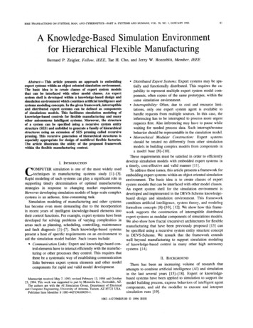
86IEEE TRANSACTIONS ON SYSTEMS, MAN, AND CYBERNETICS-PARTA SYSTEMS AND HUMANS, VOL. 26, NO. 1, JANUARY 1996factoryInext layer bSusIc'I:I!j :,,'Mu;hopfloor 1\:workstation 1.\\:in;ai ;next laver bfusinext layer bfus:::::::\t;': : : ,: ;3;Iworkstalion 2next layer bfuscFig. 11. Fractal architecture pruned to have five BFU's.levels. Thus the FMS fractal architecture model represents ahierarchical structure built from elements of a single basicdesign called a basic fractal unit (BFU). The design of theBFU incorporates a set of pertinent attributes that can fullyrepresent any level in the hierarchy [13].Fig. 10 depicts a BFU specifically designed to embodythe elements which fully describe the structure of any levelin the model hierarchy. Included within a BFU is a setof lower layer BFU's whose internal detail is hidden. Therouting controller (transporter router) sees these units asstations to which transfer batches should be delivered. It isthe responsibility of transporter routers within the lower layerBFU's to subsequently route the received batches.For illustration, the structure of one of the pruned models constructed for simulation is shown in Fig. 11 (detailedfunction of each model is described in [14]). The top ofthe hierarchy is a factory. The factory is composed of twoshop floors. The first shop floor (shopfloorl) in turn has
87ZEIGLER et al.: KNOWLEDGE-BASED SIMULATION FACTSI.div:s--ImarOUtermiotranspsIcoops Ill:inst.needd.as*:indicated Un U& provided bylnstanawriables:instanx fFig. 12. Classes in the construction of the expert router.two workstations, workstation1 and workstation2. Whereas,the second shop floor has two machines without having anyworkstation. Workstation1 has two machines and workstation2has just one machine.The transporter router is an expert system model whichcontrols routing of transporters in each BFU. It routes transporters among the lower layer BFU’s, output buffer and inputbuffer. There are total of five such DES models (one for eachBFU) whose inferencing is based on their own sets of facts,responding to the different dynamic conditions encountered ateach level (Fig. 11). The router and the rules used by its expertsystem are depicted in Fig. 12 and Appendix A.bfu :basic fractal unltbel : btu and exp. frameni :neat layerpu :processingunHdiv :dividerrouterm : router modelin-but :Input-bufferout-bur : output-buffertransp :bansporteret :experimentalframegenr :generatortransd :transducerFig. 13. System entity structure for bef (basic fractal unit with experimentalframe) architecture.IIIranapOBfacIB. Fractal Architecture ModelingThe recursive SES for the fractal architecture is shownin Fig. 13. The root of the SES, b e ! which represents themodel as being composed of BFU and ef, experimental frameconsisting of genr (generator model) and transd (transducermodel). Generator provides inputs to BFU, and transd collectsthe outputs from BFU for the calculation of output statistics.The BFU is specialized into two models, the nl (next lowerlayer) and ma (machine). The component nl is decomposedinto div (transfer batch job divider), routerm (transporterrouter), io (input/output buffer), transps (transporters) andBFU’s, where transps and BFU’s are broadcast-models, forwhich the number of components can be selected duringpruning. The io is again decomposed into in-io (input buffer)and out-io (output buffer).The fractal SES is pruned to yield a desired model architecture such as shown in Fig. 11. During recursive pruning,recursion stops when a machine ma is selected. Fig. 14 showsthe PES for the architecture in Fig. 11. This architecture isjust one of many possible that can be generated from the SES(Fig. 13). We can decide on an arbitrary number of hierarchical levels in constructing an architecture by terminating therecursion at the desired depth. Actually the depth need not beuniform. For example, the PES in Fig. 14 has three layers ofrecursion for the left side and two layers for the right side.The coupling at the BFU level is depicted in Fig. 15.IIIIrnrnaoestlmal est1Fig. 14. Pruned system entity structure of BFU.The PES in Fig. 14 does not show the experimental framepart of the architecture. There are five BFU’s in this architecture. The root is BFU@fuc (BFU for factory level).The modells at the second level (shop floor level) BFU’sare BFU@lsJD and BFU@sfl. The models BFU@wsO andBFU@wsl are workstation BFU’s within BFU@sfO. Thereare two transporters in BFU @sfl.All other BFU’s have justone transporter. Self-similar models within different BFU’s aredistinguished by the extension attached after the “@” symbol,
IEEE TRANSACTIONS ON SYSTEMS, MAN, AND CYBERNETICS-PART88-IbfubfusA SYSTEMS AND HUMANS, VOL. 26, NO. 1, JANUARY 1996IVO PORTS: message contentsINPUT PORTSi l l IIirpair that ccf&ts of a model requesting muting and a jobinfoe.g. (wsl @&info)iM :transperter model name forsignalinme current trnnspn ia donee.g. tmnsplOwslOVTPUT PORTScut: ajob-info0,.0.,i.Job-W : Uob-rype, Job-id, botch-size, scherbrlc)where zhe scherbrle Is Im Of model Mmes:iFig. 16. U 0 ports and corresponding message contents of transporter routermodel.aut-obb in-ibli int-t-obI t AbfU PO*p o n - m : c o m c t i m (message conmu)in-t-ob :input poil from banspoter(leadingrequest)in-ib inputport from bansporter(transfer batches)out-ob :output port lo vanspotem (bansfarbatches)out-t-ob :w ul port lo muter (routing request)h z k I lPat fmm[don;,dmReC q m f cW t i :wiprrt Pat to muter. * : inforroatian&on-:materklfbwRest of the port co eetionso r e f o d by r m h g ohme “phinwlporrsMd the comecrions of io model ( w f i g u r e ) .Fig. 15. DEVS BFU model.e.g., div@fac, div@s@, d i v e s f l , and so on. These extensions,which are generated during the pruning process, reflect thelevel and the module they belong to.VI. DISCUSSIONAND CONCLUSIONThe interruptibility feature developed for the DES environment is well illustrated by the transporter routing expertsystem. The current positions and velocities of all transporterswithin a BFU must be known when the transporter controller(router) makes its routing decisions. This position infomationis used to decide the departure time (in addition to thedestination) of a transporter. By controlling their departuretimes collisions among the transporters can be avoided. Whennecessary, the router model interrupts the inferencing processand sends position and velocity query messages to all thetransporters. After obtaining the needed position informationit resumes the inferencing process. Not all expert systemshells offer this interrupt capability. However, its utility asdemonstrated through simulation should suggest the need toinclude it in real world applications.Alternate structures (reconfigured structures) of the fractalarchitecture model can be generated through the recursivepruning process. The alternate structures can have differenthierarchical levels and different numbers of sub-BFU’s andtransporters within a BFU. After pruning, the details of anarchitecture model can be conveniently initialized prior tosimulation. Such rapid prototyping should greatly enhancethe ability to investigate alternative architectural solutions tomanufacturing problems in a timely manner.All h e component models in the fractal architecture modelbase are reusable. Since these models are modular and standalone components, reusability is achieved by specifying theirdesired coupling in an SES for a given application. To aidthe user in understanding the models for valid reuse, completedocumentation should be provided of the U 0 ports of models,the message structures on on these ports, and the behavioraldescription of models (Figs. 16, 17 and the Appendix illustratesuch documentation.)In conchsion, we have presented an approach to embeddingexpert systems within an object-oriented simulation environment that facilitates the creation of classes of expert systemmodel elements that can be interfaced with other model components. We have shown how interruptible distributed expertsystems can be defined as modular components of simulationsmodels. Their usefulness in fractal architectures for flexiblemanufacturing, as proposed in the literature, was illustrated.Simulation results forthis study are available in [14]. Finally,we showed how such an architecture can be specified using arecursive system entity structure. This recursive generation ofhierarchical structures is especially appropriate for design ofmultilevel flexible factories using fractal architecture concepts.However, the framework given in this paper extends wellbeyond manufacturing to support simulation modeling ofknowledge-based control in many other systems for whichhigh autonomy is the desired DELThe model gets a routing request and sends the routingdecision after inferencing the router rules. This router modelcan control more than one transporters.A. Model BehaviorInitially the model is at passive state. When a inferencingrequest comes from io model at input port in the model goesto inferencing state. If routerm is at inferencing state whena routing request arrives the routing request is placed in thequeue. The inferencing result is sent to a transporter throughoutput port out. The model returns to passive state when
ZEIGLER et al.: KNOWLEDGE-BASED SIMULATION ENVIRONMENTpassivet0IinferenceIFig. 17. State transition diagram of transporter router model.inferencing is done and the queue is empty (if
IEEE TRANSACTIONS ON SYSTEMS, MAN, AND CYBERNETICS-PART A SYSTEMS AND HUMANS, VOL.26, NO.1, JANUARY 1996 81 A Knowledge-Based Simulation Environment for Hierarchical Flexible Manufacturing Bernard P. Zeigler, Fellow, ZEEE, Tae H. Cho, and Jer:zy W. Rozenblit, Member, IEEE Abstract