Transcription
How to build aWIND TURBINEAxial flux alternator windmill plans8 foot and 4 foot diameter machines Hugh Piggott -May 2003
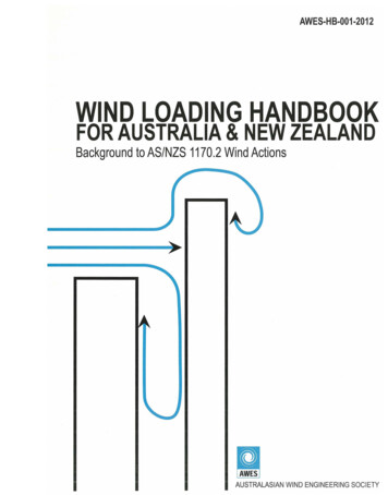
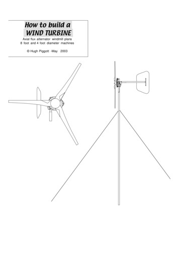
How to build a wind generator - the axial flux alternator windmill plans - May 2003 version Hugh Piggottthe results are quick for a one-off product. Mouldedfibreglass blades are usually better for batch production.Wooden blades will last for many years.IntroductionBladesThese plans describe how to build two sizes of machine.The diameter of the larger wind-rotor is 8 feet [2.4 m].The smaller machine has 4' diameter [1.2 m].The diameter is the width of the circulararea swept by the blades.page 2DIAMETERFurling systemThe plans include a description of how to construct afurling tail for the larger machine. This tail preventsoverload in high winds. This type of furling system hasbeen in use on Scoraig for decades and has passed the testof time.UnitsThe energy produced by wind turbinesdepends on the swept area more than itdoes on the alternator maximum output.AlternatorThe plans describe how to build a permanent magnetalternator.The alternator can be wired for 12, 24 or 48-volt batterycharging. Essentially this choice only affects the size ofwire and the number of turns per coil. But the towerwiring for the 12-volt version will be much heavier thanthe others. And the stator for the small machine isdifferent in thickness.The alternator design is integrated into a simple tower-topmounting arrangement (called a 'yaw bearing'). A tailvane faces the turbine into the wind. A built in rectifierconverts the electrical output to DC, ready to connect to abattery.Small wind turbines need low speed alternators. Lowspeed usually also means low power. The large machinealternator is exceptionally powerful because it contains 24large neodymium magnets. The power/speed curve for avery similar design is shown below. Maximum output isabout 500 watts under normal circumstances, but it iscapable of more than 1000 watts for short periods.The starting torque (force required to get it moving) isvery low because there are no gears, nor are there anylaminations in the alternator to produce magnetic drag.This means that the wind turbine can start in very lowwinds and produce useful power. Power losses are low inlow winds so the best possible battery charge is available.In higher winds the alternator holds down the speed of theblades, so the machine is quiet in operation, and theblades do not wear out. You can easily stop the windturbine by short-circuiting the output with a 'brakeswitch'. These features make the wind turbine pleasant tolive with.This document caters for both American readers andEuropean/UK readers, so the dimensions are in bothinches and millimetres. The mm figures are in brackets[like this]. In some of the theory sections I use metricalone, because it makes the mathematics so much easier.In some cases, the metric dimensions will be directconversions of the English dimensions, but not always.The reasons are that different size magnets are used forthe metric design, metric wire sizes are different fromAWG, and some important physical dimensions arerounded off to make more sense in mm.The US version typically uses a standard GM hub(Citation, Cavalier, etc) with five studs and a bearing at theback. The bearing housing needs a large circular hole inthe mounting at the back.I suggest you use only one system of measurement, eithermetric or 'English' and stick to that system. Your bestchoice of measurement system will depend on the magnetsize you choose.TolerancesMost of the dimensions given are nominal - the accuracy isnot critical, so you need to not follow the drawingsslavishly.The shapes of the blades are important near the tip butmuch less so near to the root (the larger, inner end of theblade).The alternator parts must be constructed and assembledwith enough accuracy that the magnets pass the coilscentrally as the machine rotates.BladesThe blades are carved from wood with hand tools. Youcan also use power tools if you prefer. Carved blades aregood for homebuilders because the process is pleasant andHugh@scoraigwind.co.uk
How to build a wind generator - the axial flux alternator windmill plans - May 2003 version Hugh PiggottCONTENTSIntroduction.2Blades. 2Alternator. 2Blades. 2Furling system . 2Units. 2Tolerances. 2Glossary.4Workshop tools.5Materials for the large machine.6Notes on workshop safety .8GENERAL . 8SPECIFIC HAZARDS . 8METALWORK . 8WOODWORKING . 8RESINS AND GLUES . 8MAGNETS . 8ELECTRICAL. 8BLADE THEORY.9Blade power . 9Blade speed . 9Blade number . 9Blade shape. 9Carving the blades .10STEP ONE is to create the tapered shape.10STEP TWO carving the twisted windward face .10STEP THREE carving the thickness . 11STEP FOUR Carve the curved shape on the back of theblade.12STEP FIVE Assembling the rotor hub. .12ALTERNATOR THEORY.15Preparing the bearing hub.15Drilling out the 1/2' [12 mm] holes in the flange.16Fabricating the alternator mounts .17Drilling the magnet rotor plates.19Making the coil winder.19Winding the coils.20ELECTRICAL THEORY.21Connecting the coils .22Hints for soldering. 22Soldering the coil tails . 22The ring neutral . 22The output wiring . 23Making the stator mould .23Mark out the shape of the stator. . 23Cut out the stator shape in plywood. . 24Wiring exit holes. 24Screw the mould to its base. 24Casting the stator.25Dry run. 25Putting it together. 25Removing the casting from the mould. 26The magnet-positioning jig .26Making the two rotor moulds.28Index hole . 28page 3Parts of the moulds .28Casting the rotors . 29Preparation.29Handling the magnets.29Dry run .29Checking for magnet polarity .29Putting it together .29FURLING SYSTEM THEORY. 30Why furl? .30How the furling tail works .30Controlling the thrust force . 31Fabricating the tail hinge. 32The tail itself.33Cutting out the tail vane . 34Mounting the heatsink . 34Assembling the alternator. 35Preparation.35Hub and shaft.35Back magnet rotor.35The stator.35Front magnet rotor.36Testing the alternator . 36Short circuit tests .36AC voltage tests .36DC voltage tests .36Connecting the rectifier. 37Connecting the battery . 37Fuses or circuit breakers . 37Connections. 37Brake switch . 37Choosing suitable wire sizes. 37Wire type .38Fitting and balancing the blades . 39Checking the tracking .39Balancing the rotor.39Fine tuning .39ADDITIONAL INFORMATION. 40Guyed tower ideas . 40Controlling the battery charge rate. 41Shunt regulator circuit . 41List of components required. 41Using polyester resin. 42Mould preparation .42Small machine supplement. 43Blades .43Bearing hub .43The shaft .44Rotor moulding .44Stator mould.46Assembly of the stator.46The yaw bearing .47The tail bearing and tail .47Wiring up the battery .48Hugh@scoraigwind.co.uk
How to build a wind generator - the axial flux alternator windmill plans - May 2003 version Hugh PiggottGlossaryAC-Alternating current as produced by the alternator.Allthread - USA word for 'threaded' or 'spun' rod orstuddingBrake switch - A switch used to short-circuit the wiresfrom the alternator so that it stops.Catalyst - A chemical used to make the polyester resin setsolid. Catalyst reacts with 'accelerator' already present inthe resin mix. The heat of reaction sets the polyester.Cavalier - A make of car. The cavalier in the UK is not thesame as the Cavalier in the USA but both have usefulwheel hubs.DC - direct current with a positive and a negative side, asin battery circuits.Diameter - The distance from one side of a circle toanother. The width of a disk right across the middle.page 4Phase - The timing of the cyclical alternation of voltage ina circuit. Different phases will peak at different times.Polyester - A type of resin used in fibreglass work. Alsosuitable for making castings.Power - the rate of delivery of energyRectifier - A semiconductor device that turns AC into DCfor charging the battery.Root - The widest part of the blade near to the hub at thecentre of the rotor.Rotor - A rotating part. Magnet rotors are the steel diskscarrying the magnets past the stator. Rotor blades are the'propeller' driven by the wind and driving the magnetrotors.Soldering - A method for making electrical connectionsbetween wires using a hot 'iron' and coating everythingwith molten solder.Drag - A force exerted by the wind on an object. Drag isparallel to the wind direction at the object. (see Lift)Stator - An assembly of coils embedded in a slab of resinto form part of the alternator. The magnets induce avoltage in the coils and we can use this to charge a battery.Drop - Used here to describe a certain measurement of theshape of a windmill blade. The 'drop' affects the angle ofthe blade to the wind.Styrene monomer - A nasty smelling solvent in thepolyester resin mix.Flux - The 'stuff' of magnetism. Similar to 'current' inelectricity. It can be visualised as 'lines' coming out of onepole and returning to the other.Furling - A protective action that reduces exposure toviolent winds by facing the blades away from them.Jig - A device used to hold the magnets in place beforesetting them in resin.Leading edge - The edge of a blade that would strike anobject placed in its path as the rotor spins.Lift - A force exerted by the wind on an object. Lift is atright angles to the wind direction at the object. (see Drag)Mould - A shaped container in which resin castings areformed. The mould can be discarded after the casting hasset.Multimeter - A versatile electrical test instrument, used tomeasure voltage, current and other parameters.Neodymium - The name given to a type of permanentmagnet containing neodymium, iron and boron. Thesemagnets are very strong and getting cheaper all the time.Offset - An eccentric position, off centre.Talcum powder- A cheap filler powder used to thicken theresin and slow its reaction (prevent it overheating).Tail - A projecting vane mounted on a boom at the back ofthe windmill used to steer it into or out of the windautomatically.Tap - a tool for making thread inside holes so you can fit ascrew into the hole.Thrust - The force of the wind pushing the machinebackwards.Tower - The mast supporting the windmill.Trailing edge - The blade edge furthest from the leadingedge. The trailing edge is sharpened, so as to release thepassing air without turbulence.Wedges - Tapered pieces of wood used to build up theblade thickness and increase its angle to the wind near theroot.Workpiece - The piece of wood or metal being shaped inthe workshop.Yaw bearing - the swivel at the top of the tower on whichthe windmill is mounted. The yaw bearing allows thewindmill to face the wind.Hugh@scoraigwind.co.uk
How to build a wind generator - the axial flux alternator windmill plans - May 2003 version Hugh PiggottWorkshop toolsMECHANICALTOOLS electric welder 'saws-all' oxy-acetylene torch welding mask chipping hammer vice G clamps pillar drill cordless drill handheld electric drill-- 1/2" [13mm] chuck drill bits holesaws 1/2" [M12] tap angle grinder belt sander cut-off machine hacksaw cold chisel hammer centre punch files tin snips tape measure steel ruler set square protractor scriber chalk compasses angle/bevel gauge spirit level vernier calipers ear protectors safety glasses/goggles face masksscrewdriverspliersvice grips10"adjustable wrenchcombinationwrenches 3/8"-3/4"[10-19mm] socket wrenches andratchets 10-19mmWOODWORKINGTOOLS vice G clamps hammer wooden mallet draw knife spoke shave planes large andsmall wood chisel oilstone jig saw screwdrivers handsaw circular saw pencil tape measure steel ruler set square spirit level calipersPLASTICS ETCTOOLSHugh@scoraigwind.co.ukpage 5 multimeter surform/rasp weighing scales spoons, knives formixing safety glasses face masks screwdrivers knife scissors felt pen soldering iron pencils tape measure steel ruler spirit level MiscellaneousconsumablesWelding rods, grindingdisks, hacksaw blades.Epoxy glue and bondofor misc. repairs.Lead flashing forbalancing blades(1/8" x 12" x 12" approx.piece)Heatsink compound forrectifier mountingSome extra tools forthe smaller machine1" diameter woodboring bit for moulds.
How to build a wind generator - the axial flux alternator windmill plans - May 2003 version Hugh PiggottMaterials for the large machineBLADE WOODpage 61 Tail1 1/4"4' 6"1 5/8"1/8"boomnominal bore[1350 mm][42.2][3mm1 tailhinge1 " nominalbore8"[200 mm]1 5/16"[33.4]1/8"[3mmPiecesSteel diskDiam.ThickHole2 1/2[65 ]PiecesMaterialLengthWidthThick3Light, straight4 feet6"1 1/2"bladesgrained wood[1200mm][150 mm][37mm]2Magnet rotordisks12 " O.D.[300 mm]5/16"8 mm1Off-cut ofEnough toOver 3"1 1/2"wedgeswood, withsome straight-grainedfind someniceportions[75mm][37mm]1 tailbearinSteel platedisk or1 5/8"[42.2]5/16"[8mm]g capsquareminimum1 yawbearinSteel platedisk or2 1/2"[65]5/16"[8mm]g capsquarePiecesMaterialLengthWidthThicSteel plate4"2 1/4"3/8"[100][56 mm][10]Steel bar12" [300]1 1/2"[30]5/16'portionsPLYWOOD ETC.PiecesMaterialLengthWidthThick12Hardboard16" [400]16" [400]1/8" [3 ]tailhinge1jigHardboardor plywood12" [300]12" [300]1/4" [6]12islandPlywoodfor magnet6" [158]6" [158]1/2" larger[9] smaller2Steel angle10 1/2"[267 mm]2"[50 mm]1/4"[6 ]1Exterior36"24"3/8"2Steel angletailvaneplywood fortail vane[900 mm][600][9 mm]2"[50mm]2"[50 mm]1/4"[6 ]1Steel angle2Exterior10"10 "1/2"4"[100 mm]2"[50 mm]1/4"[6 ]hubdisksqualityplywood[250mm][250mm][13 mm]Aluminium9"2"3/16"[220 mm][50]1Plywood24" [600]24" [600]angle orchannel[5mm]Plywood4"[100 winder2Smoothlid andbasefacedboard4Floor board24" [600]24" [600]Item 76 from www.wondermagnet.com[46 x 30 x 10 mm grade 40 NdFeB see below3/4" [19]suggestedsize16" [400]16" [400]3/4" [19]rotorsSTEEL AND ALUMINIUMSteel pipeLengthOverallDiam.WallThick1Yawbearg.2" nominal12"[300 mm]2 3/8"60.3 OD1/8"[3mm]1Yaw1 1/2 "16"1 7/8"1/8"nominal bore[400 mm][48 mm]Fibreglass resinUK SOURCES OF PARTSGlasplies 2, Crowland St. Southport,etcLancashire PR9 7RL(01704) 540 6 2 6MagnetsCERMAG Ltd. 94 Holywell Rd, SheffieldSA4 8AS (0114) 244 6 1 3 6Piecesbrg.Magnet blocks 2 x 1 x 1/2" grade 35 NdFeB[3mm]Winding wireRectifiers andothercomponentsHugh@scoraigwind.co.ukor sales@magna-tokyo.com EC WIRE LTD (01924) 266 3 7 7Percy Hawkins(01536) 523 2 2FARNELLwww.farnell.comJPR Electronicswww.jprelec.co.ukwww.Maplin.co.uk
How to build a wind generator - the axial flux alternator windmill plans - May 2003 version Hugh PiggottSTEEL FASTENERSWIRE ETCPiecesMaterialLengthWidth1Stainless steel5'1/2"mountsall-thread rod[1.5 m][M12]40Stainless steel1/2"nuts[M12]10Stainless steelwashers1/2"[M12]4for rotormouldsBolts,nuts washers3"[70 mm]1/2"[12 mm]4coil formerNails or pins4" ?[100 mm ?]3/16"[5 mm]1Stud or bolt6" approx.3/8"winder(winder shaft)[150 mm][10 mm]5winderNuts andwashers3tail vaneBolts, nutswashers2heatsink6WeightMaterialTurns per coil& sizeVoltag6 lbs.[3 kg]for tenEnamelwindingwire, called80 turns of #15 wire[90 turns of 1.4 mm]12 V160 turns of #18 wire24Vcoilsmagnet wirewww.otherpower.com[180 turns of 1 mm]Flexible wirewith high#14 [2 mm] or similar12-V,temperatureinsulation#18 [.75 MM] bundledin a protective sleeve24V or48V30'[10 m]3' [1 m]320 turns of #21 wire[360 turns 0.7 mm]solder wire3/8"[10 mm]3' [1 m]Insulationsleeving2 1/2"[60 mm]3/8"[M10]5BridgerectifiersBolts and nuts1" [25]1/4" [6]1ConnectorblockBolts and nuts1" [25]3/16" [5]Large enough to fitover the solder joints35A 6-800V single phasehttp://www.rfparts.com/bridge.htmBEARING HUBWood screws1 1/4" [32 mm]1Automotive rear hub with flanged shaft forconvenient mount to wind turbine.FIBERGLASS RESIN3"Material6lbs[2.5 kg]Polyester casting resin or fiberglass resin inliquid form (premixed with accelerator).Peroxide catalyst to suit.5 lbs.[2.2 kg]Talcum powder3' x 3'[1 x 1 m]Fiberglass cloth (or use chopped strand mat)1 ounce per sq. foot [300g per sq. metre]UKVERSIONHUBWax polishSilicone in coredrectifiers100page 7SHAFT
How to build a wind generator - the axial flux alternator windmill plans - May 2003 version Hugh PiggottNotes on workshop safetyGENERALWorkshop safety depends on correct behaviour. Thereare intrinsic dangers. Be aware of the risks to yourselfand others and plan your work to avoid hazards.Protective clothing will reduce the risks, but withoutawareness the workshop will not be safe.Keep the workshop tidy. Avoid trailing leads, precariousbuckets or other unnecessary hazards, which peoplecould trip over or spill.Watch out for others, to avoid putting them at risk andbeware of what they might do which could put you atrisk.Wear protective clothing - eye protection, gloves, helmet,mask, etc as appropriate to prevent danger. Avoid looseclothing or hair, which could be trapped in rotating toolsand pulled inwards.page 8WOODWORKINGTake care with sharp tools. Clamp the workpiecesecurely and consider what would happen if the toolslips. Watch out for others.Wear a dust mask when sanding. Do not force others tobreathe your dust. Take the job outside if possible.Wood splinters can penetrate your skin. Take care whenhandling wood to avoid cutting yourself.RESINS AND GLUESThe solvents in resins can be toxic. Wear a mask andmake sure there is adequate ventilation.Avoid skin contact with resins. Use disposable gloves.Plan your work to avoid spillage or handling of plasticresins and glues. Be especially careful of splashing resinin the eyes.Take care when handling tools which could cut or injureyourself or others. Consider the consequences of the toolslipping or the workpiece coming loose. Attend to yourwork, even when chatting to others.MAGNETSMagnets will erase magnetic media such as credit cards,sim cards, camera memory cards, and damage watches.Remove suchlike from pockets before handling magnets.SPECIFIC HAZARDSMagnets fly together with remarkable force. Beware oftrapping your fingers. This is the most likely cause ofsmall injuries. Slide magnets together sideways withextreme caution.METALWORKGrinding, sanding, drilling etc can produce high velocitydust and debris. Always wear a mask when grinding.Take care that any sparks and grit are directed into a safezone where they will not injure anyone, or cause fires.Consider how the tool might come into contact withfingers or other vulnerable body parts.Welding, drilling etc makes metal hot, so take care whenhandling metalwork during fabrication.Welding should take place in a screened space where thesparks will not blind others. Wear all protective clothingincluding mask. Do not inhale the fumes. Protect theeyes when chipping off slag. Do not touch live electrodesor bare cable.Steel mechanisms can fall or fold in such a way as tobreak toes or fingers. Think ahead when handling steelfabrications to prevent injury. Clamp the workpiecesecurely.Take great care when lifting steel assemblies, to avoidback injury. Keep well clear of towers and poles thatcould fall on your head. Wear a safety helmet whenworking under wind turbines.ELECTRICALCheck for dangerous voltages before handling anywiring.Battery voltage systems are mostly free from dangerousvoltages, but there is a shock hazard from wind turbinesrunning disconnected from the battery. Under theseconditions the output voltage can rise to dangerouslevels.Even at low voltages there is a danger of burns fromelectric arcs or short circuits. All circuits from batteriesshould have fuses or circuit breakers to preventsustained short circuits causing fires.Be especially careful with batteries. Metal objectscontacting battery terminals can cause large sparks andburns. Gas inside the battery can be ignited, causing anexplosion that spatters acid in the eyes. Acid will burnclothing and skin. Avoid contact, and flush any affectedparts with ample water. Take care when lifting andmoving batteries to prevent back injury or acid spills.Hugh@scoraigwind.co.uk
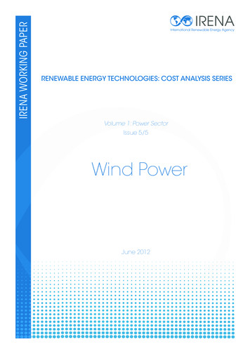
How to build a wind generator - the axial flux alternator windmill plans - May 2003 version Hugh PiggottBLADE THEORYBlade powerThe rotor blade assembly is the engine powering thewind generator. The blades produce mechanical powerto drive the alternator. The alternator will convert thisinto electrical power. Both types of power can bemeasured in watts.It's a good idea to use metric units for aerodynamiccalculations. The power (watts) in the wind blowingthrough the rotor is given by this formula:1/2 x air-density x swept-area x windspeed3(where air density is about 1.2 kg/m3)The blades can only convert at best half of the windÕstotal power into mechanical power. In practice onlyabout 25 -35% is a more typical figure for homebuiltrotor blades. Here is a simpler rule of thumb:Blade power 0.15 x Diameter2 x windspeed3 0.15 x (2.4 metres)2 x (10 metres/second)3 0.15 x 6 x 1000 900 watts approx.(2.4m diameter rotor at 10 metres/sec or 22 mph)Diameter is very important. If you doublethe diameter, you will get four times asmuch power. This is because the windturbine is able to capture more wind.Windspeed is even more important. Ifyou can get double the windspeed, you willget eight times as much power.page 9Blade numberPeople often ask ÒWhy not add more blades and getmore power?Ó It is true that more blades will producemore torque (turning force), but that does not equate tomore power. Mechanical power is speed multiplied bytorque. For electricity production you need speed morethan you need torque. Extra blades help the machine tostart to turn slowly, but as the speed increases the extradrag of all those blades will limit how much power it canproduce. Multibladed rotors work best at low tip speedratios.Fast turning blades generate much more lift per squareinch of blade surface than slow ones do. A few, slenderblades spinning fast will do the same job as many wideones spinning slowly.Blade shapeAny rotor designed to run at tip speed ratio 7 would needto have a similar shape, regardless of size. Thedimensions are simply scaled up or down to suit thechosen diameter.BLADE STATIONSDIAMETERCHORD WIDTHTHICKNESSWIDTHLEADINGEDGEBlade speedThe speed at which the blades rotate will depend on howthey are loaded. If the alternator has high torque and ishard to turn, then this may hold the speed down too low.If the wiring is disconnected and electricity production isdisabled, the rotor will accelerate and Ôrun awayÕ at amuch higher speed.Rotor blades are designed with speed in mind, relative tothe wind. This relationship is known as Ôtip speed ratioÕ(tsr). Tip speed ratio is the speed the blade tips traveldivided by the windspeed at that time.In some cases the tips of the blades move faster than thewind by a ratio of as much as 10 times. But this takesthem to over 200 mph, resulting in noisy operation andrapid erosion of the blades edges. I recommend a lowertip speed ratio, around 7.We are building a rotor with diameter 8 feet [2.4metres]. We want to know what rpm it will run at best ina 7 mph [3 m/s] wind when first starting to produceuseful power.Rpm windspeed x tsr x 60/circumference 3 x 7 x 60 /(2.4 x 3.14) 167 rpmDROPBLADE SECTIONBLADEANGLETRAILINGEDGEOUTLINE OF WOODEN WORKPIECEWe specify the shape at a series of stations along thelength of the blade. At each station the blade has ÔchordwidthÕ, 'blade angle' and 'thickness'. When carving ablade from a piece of wood (a ÔworkpieceÕ) we caninstead specify the width of the workpiece and also whatI call the ÔdropÕ. These measurements will then producethe correct chord width and blade angle. The drop is ameasurement from the face of the workpiece to thetrailing edge of the blade.The shape of the blade near the root may vary fromone wind turbine to another. A strongly twisted andtapered shape is ideal. But in some cases a much lesspronounced twist is also successful. I prefer the strongtwist and taper becausea) it is strongb) it is starts up better from rest,and c) I think it looks better.In fact it is not going to make a huge difference if theroot is a different shape. The blade root shape willprobably be determined more by practical issues such asavailable wood and the details of how to mount it to thealternator than by aerodynamic theory.Hugh@scoraigwind.co.uk
How to build a wind generator - the axial flux alternator windmill plans - May 2003 version Hugh PiggottCarving the bladesPieces3MaterialLight,straightgrained woodMaterialsLength4 feet[1200m
How to build a wind generator - the axial flux alternator windmill plans - May 2003 version ' Hugh Piggott page 2 Hugh@scoraigwind.co.uk Introduction Blades These plans describe how to build two sizes of machine. The diameter of the larger wind-rotor is 8 f