Transcription
INTRODUCTIONThis manual is intended to guide the user through basic service of Manitou front forks. Service issupported by the identification of common parts and assemblies that have been assembled intoService Kits. The purpose of this manual will be to describe conditions that may drive the needfor service and to provide installation instructions for the kits.Due to the time-consuming nature of suspension fork service, at this time our primary focus is tooffer service kits that minimize the amount of downtime and labor involved.Important information is highlighted in this manual by the following notations:WARNINGFailure to follow WARNING instructions could result in severe injury or death to theperson inspecting or repairing the suspension fork or the user.CAUTIONA CAUTION a caution indicates special precautions that must be taken to avoid damage tothe product.NOTEA NOTE provides key information to make procedures easier or clearerGENERAL WARNING: Suspension forks by design can contain preloaded springs, gasesand fluids under extreme pressure and warnings contained in this manual must beobserved to reduce the possibility of injury or possible death. Following theseinstructions can help you reduce the risk of being injured. Any questions in regards to theinformation in this manual should be directed to Manitou Customer Service at (888) 6863472.WARNING: Suspension forks uses preloaded spring(s) to provide compression springresistance. This system must be relieved of preload prior to servicing. Failure to relieveair pressure could result in injury or possible death.CAUTION: Suspension forks use precision machined aluminum and other soft alloy components.Using correct tools for assembly is essential to prevent damage.2012 SERVICE MANUAL
This manual is divided up into different sections, each one pertaining to a different part of theservicing of your fork. Below is a list of our fork models and which sections you will use to serviceyour particular fork.Circus Comp/Match/Tower Comp Forks1.Section 1 – Casting Removal2.Section 3 – Dust Seal Replacement3.Section 4 – Coil Spring Service4.Section 8 – Absolute Service5.Section 10 – Casting InstallationMinute Pro/Tower Pro Forks1.Section 1 – Casting Removal2.Section 3 – Dust Seal Replacement3.Section 5 – MARS Air Spring Service4.Section 8 - Absolute Service5.Section 10 – Casting InstallationCircus Expert/Minute Expert/Tower ExpertForks1.Section 1 – Casting Removal2.Section 3 – Dust Seal Replacement3.Section 7 – ACT Air Service4.Section 8 – Absolute Service5.Section 10 – Casting InstallationR7 Forks1.Section 1 – Casting Removal2.Section 3 – Dust Seal Replacement3.Section 6 – TS Air Service4.Section 8 – Absolute Service5.Section 10 - Casting InstallationR7 MRD Forks1.Section 2 – MRD Casting Removal2.Section 3 – Dust Seal Replacement3.Section 6 – TS Air Service4.Section 9 – Absolute MRD Service5.Section 11 – MRD Casting InstallationMarvel Expert Forks1.Section 1 – Casting Removal2.Section 3 – Dust Seal Replacement3.Section 8 – ISO Air Service4.Section 8 – Absolute Service5.Section 10 – Casting InstallationMarvel Pro Forks1.Section 2 – MRD Casting Removal2.Section 3 – Dust Seal Replacement3.Section 8 – ISO Air Service4.Section 9 – Absolute MRD Service5.Section 11 – MRD Casting Installation 2012 SERVICE MANUAL
Table of ContentsPage NumberSectionSection 1 - Casting RemovalSection 2 - MRD Casting RemovalSection 3 - Dust Seal ReplacementSection 4 - Coil Spring ServiceSection 5 - MARS Air Spring ServiceSection 6 - TS Air Spring ServiceSection 7 - ACT Air Spring ServiceSection 8 - ISO Air Spring ServiceSection 9 - Absolute ServiceSection 10 - Absolute MRD ServiceSection 11 - Casting InstallationSection 12 - MRD Casting InstallationOil Height ChartFork Exploded Diagrams4567-89 - 1011 - 1213 - 1415 - 1617 - 1819 - 2021222324 - 34Contact InformationHayes Bicycle Group6750 W Florist AveMilwaukee, WI 53218Toll Free:Direct:FAX:E-mail:Web site:(888) 686-3472(262) 242-4300(414) .com2012 SERVICE MANUAL
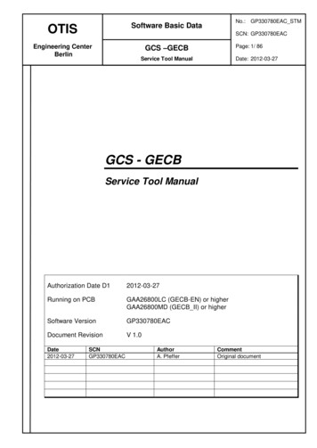
Casting Removal1. From the left leg dropout (Left when sitting on the bike), usea 10 or 11mm wrench to remove the compression rod screw.(Fig. 1)2. From the right leg dropout, if the fork has adjustable rebound, the knob will need to be removed. Screw the reboundall the way in (clockwise) remove the 2mm hex screw insidethe knob by turning it counter clockwise. Remove the knob bypulling gently away from the fork. (Fig. 2)FIG. 13. Use an 8mm hex wrench to turn the damper clockwise untilit can be pushed into the casting. (Fig. 3)4. Remove crown/steer/inner leg assembly from the outer legcasting by pulling firmly on the casting. If the fork uses theSemi bath Lubrication system, use caution as the oil that is inthe casting will be released when the casting is removed, it isbest to do this over some type of catch pan.FIG. 2FIG. 3 2012 SERVICE MANUAL
MRD Casting Removal1. From the left leg dropout (Left when sitting on the bike),use a 10 or 11mm wrench to remove the compression rodscrew. (Fig. 1)2. Remove the blue rebound knob on the bottom of theright leg with a 1.5mm Allen wrench. Be cautious of thedetent balls and springs under the knob as they are verysmall and easily lost. (Fig. 2)3. Remove the detent balls and springs from the DetentHousing. (Fig. 3)FIG. 14. Remove the Detent housing by unscrewing it counterclockwise using a green Park Tool pin spanner (or similartool) inserted into the holes that the springs and detentballs sit in. (Fig. 4)5. Using a 7mm or 8mm Allen wrench, turn the reboundassembly clockwise until it can be pushed into the casting. (Fig. 5)FIG. 26. Remove crown/steer/inner leg assembly from the outerleg casting by pulling firmly on the casting. The fork usesthe Semi bath Lubrication system, use caution as the oilthat is in the casting will be released when the casting isremoved, it is best to do this over some type of catch pan.FIG. 3FIG. 52012 SERVICE MANUALFIG. 4
Dust Seal Replacement1. Before replacing the dust seals you will need to removethe lower casting. Refer to the Casting Removal or MRDCasting Removal instructions depending on which modelfork you have.FIG. 12. To remove the dust seals, first remove the seal tensionsprings (otherwise they will get damaged), then take alarge flat-bladed screwdriver and insert the tip between thebottom of the seal and the top of the foam wiper. (Fig. 1)3. Push down on the screwdriver. This will pop the seal outof the casting. Next remove the foam oil ring. (Fig. 2)4. Oil the foam rings (new or after cleaning the old rings)with a small amount of semi-bath oil and place them in thetop of the casting above the Upper Bushings. (Fig. 3)FIG. 25. Install the dust seal into the leg, use a large socket orpiece of round tubing that is large enough in diameter topress on the outside shoulder of the seal rather than putting pressure on the sealing lip and spring so that they arenot damaged. (Fig. 4) Repeat steps 1-4 for the oppositecasting leg.FIG. 3 2012 SERVICE MANUALFIG. 4
Coil Spring Service1. Using a 2mm Allen wrench, remove the knobfrom the preload adjuster. (Fig. 1)2. Remove the preload adjuster from the fork usinga 20mm socket. (Fig. 2)FIG 13. Pull the coil spring out of the stanchion leg.4. Remove travel spacer and bottom out bumperfrom the end of the compression rod assembly.(Fig. 3)5. Remove the compression rod assembly fromthe stanchion leg. The compression rod comesout from the top of the stanchion leg. Turn the forksideways or upside down to get the compressionrod out of the leg. (Fig. 4)FIG 26. Inspect compression rod and top-out bumper. Ifdamaged replace.7. Install compression rod assembly into the stanchion leg. Insert through the top of the stanchionleg and maneuver the rod until it drops through thehole at the bottom of the stanchion leg.8. Lightly grease the spring and install into stanchion leg.FIG 39. Install the preload adjuster into the fork leg.Tighten down using a 20mm socket to 5,1- 6,2 Nm(45-55 in. lbs).10. Using a 2mm Allen wrench, install the preloadknob onto the adjuster. Tighten knob down to 0,50,7 Nm (4-6 in. lbs).11. Install bottom-out bumper and travel spaceronto the end of the compression rod.2012 SERVICE MANUALFIG 4
12. The casting needs to be removed prior to servicing the coil spring. Refer to the Casting RemovalInstructions first.13. Turn the preload knob counter-clockwise until itstops to relieve the preload on the spring.TRAVEL CONVERSION ON MATCHAND CIRCUS COMP 80/100MM FORKS1. The Match/Circus Comp 80 and 100mm forkscan be converted to either travel by moving aspacer on the compression rod. Follow steps 1-7 toremove the compression rod form the fork.2. The travel of the fork is determined by a plasticspacer. The spacer being on top of the flange onthe compression rod will cause the fork to have100mm of travel. (Fig. 5). The spacer being on thebottom on the flange will cause the fork to have80mm of travel. (Fig. 6)100mmFIG. 5 80mmFIG. 62012 SERVICE MANUAL
MARS Air Spring ServiceWARNING This fork uses compressed air to provide spring resistance andmust be relieved of pressure prior to servicing. Failure to relieve air pressurecould result in injury or possible death.FIG. 11. Before servicing the Mars Air System you will need toremove the lower casting. Refer to the Casting Removal orMRD Casting removal instructions depending on which forkmodel you have.2. Release the air from the fork by depressing the valvecore on the Schrader valve.3. Remove the air cap from the fork using a 20mm socket.(Fig. 1)4. Unthread the compression rod assembly from the bottomof the stanchion using a 22mm wrench and remove fromfork. (Fig. 2)FIG. 25. Remove the spring from the stanchion. (Fig. 3)6. Remove the air pushrod from the stanchion by pullingit out with needle nose pliers or by turning the fork upsidedown and letting it fall out. (Fig. 4)7. The next step is to remove the air piston. First look upinto the stanchion leg from the bottom. You will see an airshelf in the fork with a hole in the center of it. You will wantto push the air piston out the top of the stanchion leg witha long Allen wrench or similar tool. When inserting the toolinto the stanchion leg you must be sure it goes throughthe center hole of the air shelf to push the piston out. Theair shelf should never be removed from the fork. Doingso would damage the fork and require you to replace thecrown/steer assembly of the fork.FIG. 3FIG. 42012 SERVICE MANUAL
8. Apply grease around the side of the new air piston.We suggest using Manitou Prep M grease. (Fig. 5)9. Install air piston into the top of the stanchion leg andpush it past the threads. (Fig. 6)10. Pour in 5cc’s of semi-bath oil on top of the air piston. (Fig. 7)11. Install air cap onto the stanchion leg using a 20mmsocket and tighten to 6,8-8,0 Nm [60-80 lbf*in]FIG. 512. Turn the fork upside down and insert the air pushrod into the bottom of the stanchion. The long end ofthe pushrod goes towards the top of the fork and mustdrop through the center hole of the air shelf discussedin Step 7. Drop the pushrod into the stanchion leg andmaneuver it until you feel it drop through the centerhole.13. Lightly grease the spring and insert into the stanchion leg.FIG. 614. Install compression rod assembly into the stanchionleg using a 22mm wrench and tighten down to 6,8-8,0Nm [60-80 lbf*in]FIG. 7102012 SERVICE MANUAL
TS AIR SERVICEWARNING This fork uses compressed air to provide spring resistance andmust be relieved of pressure prior to servicing. Failure to relieve air pressurecould result in injury or possible death.1. Before servicing the TS Air system you will need toremove the lower casting. Refer to the Casting Removalor MRD Casting removal instructions depending on whichfork model you have.FIG. 12. Release all air from the system by depressing the valvecore on the Schrader valve.3. Using a 20mm socket, remove the air cap from the fork.(Fig. 1)4. Remove compression rod assembly from the bottom ofthe stanchion using a 22mm wrench. (Fig. 2 & 3)5. Using a long Allen wrench or similar tool, push the airpiston down and out the bottom of the stanchion leg. (Fig.4)FIG. 26. Apply grease around the side of the new air piston. Wesuggest using the Manitou Prep M grease. (Fig. 5)7. Install air piston into the fork stanchion. Install by pushing the piston in through the top of the stanchion and pushit past the threads. (Fig. 6)8. Install compression rod assembly into the bottom of thestanchion and tighten down the end cap using a 22mmwrench. Tighten to 9,0–11,3 Nm [80-100 lbf*in]FIG. 39. Pour in 5cc’s of semi-bath oil on top of the air piston.FIG. 42012 SERVICE MANUAL11
FIG. 512FIG. 62012 SERVICE MANUAL
ACT Air ServiceWARNING This fork uses compressed air to provide spring resistance andmust be relieved of pressure prior to servicing. Failure to relieve air pressurecould result in injury or possible death.FIG. 11. The casting needs to be removed prior to servicingthe ACT Air system. Refer to the Casting Removalsection for instructions on how to do this.2. Release all air from the system by depressing thevalve core on the Schrader valve.3. Using a 20mm socket or wrench remove the top aircap assembly from the fork. (Fig. 1)4. Remove the spring from the fork. (Fig. 2)FIG. 25. Using a 22mm wrench unthread the compressionrod assembly end cap and remove the assembly fromthe fork uppers. (Fig. 3)6. Replace the air piston o-ring on the compressionrod assembly. (Fig. 4)7. Apply a small amount of grease to the o-ring andinsert compression rod assembly back into the forkuppers. Tighten the end cap down to 9.0-11.3 Nm(80-100 in. lbs)FIG. 38. Grease the spring and place it into the fork uppersfrom the top.9. Install air cap. Tighten down to 6.8-9.0 Nm (60-80in. lbs)10. Using a shock pump, fill fork to desired air pressure.FIG. 42012 SERVICE MANUAL13
TRAVEL CONVERSION ON DRAKE/CIRCUSEXPERT/MINUTE EXPERT 80 and 100mmFORKS1. The Drake 80 and 100mm forks can be converted toeither travel by moving a spacer on the compression rodassembly. Follow Steps 1-5 above to remove the compression rod assembly.2. The travel of the fork is determined by a plastic spacer.The spacer being on the bottom of the air piston will causethe fork to have 80mm of travel. The spacer being on topof the piston will cause the fork to have 100mm of travel.Fig. 5 on this page shows the placement of the spacer for80mm of travel. Fig. 6 on this page shows the placement ofthe spacer for 100mm of travel.100mm80mmFIG. 514FIG. 62012 SERVICE MANUAL
ISO Air Spring ServiceWARNING This fork uses compressed air to provide spring resistance andmust be relieved of pressure prior to servicing. Failure to relieve air pressurecould result in injury or possible death.FIG. 11.Before servicing the Mars Air System you will need toremove the lower casting. Refer to the Casting Removal orMRD Casting removal instructions depending on which forkmodel you have.2. Release the air from the fork by depressing the valvecore on the Schrader valve.3. Remove the air cap from the fork using a 20mm socket.(Fig. 1)4. Unthread the compression rod assembly from the bottomof the stanchion using a 22mm wrench and remove fromfork. (Fig. 2 &3)5. Remove the air piston from the stanchion leg. There aretwo ways to do this. You can use a long Allen wrench ordowel rod to push the air piston through and out the bottomof the stanchion leg. (Fig. 4) You can alternatively use a6mm bolt and thread it into the center of the piston and pullit out the top of the fork leg. (Fig. 5) The second method isconvenient when you are just servicing the air piston anddo not want to disassemble the fork.FIG. 2FIG. 36. Apply grease around the side of the new air piston. Wesuggest using Manitou Prep M grease. (Fig. 6)7. Install air piston into the top of the stanchion leg andpush it past the threads.8. Pour in 5cc’s of semi-bath oil on top of the air piston.(Fig. 7)9. Install air cap onto the stanchion leg using a 20mmsocket and tighten to 6,8-8,0 Nm [60-80 lbf*in]2012 SERVICE MANUALFIG. 415
FIG. 5FIG. 6FIG. 7162012 SERVICE MANUAL
Absolute ServiceDisassembly1. The casting needs to be removed prior to servicing the damping side of the fork. Refer to the Casting Removal instructions.2. Using a 2mm Allen wrench, remove the adjusterknob from the top of the fork. (Fig. 1) Be carefulwhen removing the knob as there are two detent ballbearings under it. Remove the detent ball bearingsand springs.FIG. 13. Using a 24mm socket remove the Absolute damper from the stanchion leg. (Fig. 2)4. Pour the damping oil out of the stanchion leg.5. Turn the fork upside down and using a 22mm boxend wrench, remove the rebound damper assemblyfrom the stanchion. (Fig. 3)6. Check o-rings on rebound and compression assemblies and replace any that are worn or damaged.FIG. 2Assembly1. Install the rebound damper assembly into thebottom of the stanchion leg. Using a 22mm box endwrench tighten down to 9,0-11,3 Nm [80-100 lbf*in].2. The next step is to fill the fork with oil and installthe compression damper. To ensure proper oil heightthe casting must be installed prior to filling. If youhave other service to perform on the fork continueonto the appropriate section and finish that first. Ifnot refer to the Casting Installation instructions toinstall the casting back onto the fork.2012 SERVICE MANUALFIG. 317
3. Once the casting is installed you are ready tofill the fork with oil. Pour oil into the stanchion leguntil it is about a quarter of the way up. (Fig. 4)Cover the hole in the stanchion with a rag andcycle the fork 7-10 times. Failure to do this willcause an incorrect oil height. After cycling the fork,continue filling the stanchion leg with oil to the oilheight specified on the Oil Height Chart found inthis manual for your fork model.4. Install the Absolute damper into the stanchionand tighten down using a 24mm socket to 6,8-9,0Nm [60-80 lbf*in].FIG. 45. Install detent springs and ball bearings into theholes on the top cap. You want them placed inholes opposite of each other. (Fig. 5)6. Install adjuster knob and using a 2mm Allenwrench tighten down to 0,5-0,7 Nm [4-6 lbf*in].FIG. 5182012 SERVICE MANUAL
Absolute MRD ServiceDisassembly1. The casting will need to be removed prior to servicingthe damping side of the fork. Refer to the MRD CastingRemoval Instructions.FIG. 12. Using a 2mm Allen wrench, remove the adjuster knobfrom the top of the fork leg. (Fig. 1) Be careful whenremoving the knob as there are two detent ball bearingsbelow the knob. Remove the detent springs from the topcap.3.Remove the Absolute damper from the stanchion legusing a 24mm socket. (Fig. 2)4. Pour the damping oil out of the fork leg.FIG. 25. Turn the fork upside down and using a 15mm openend wrench, unthread the rebound damping assemblyfrom the bottom of the stanchion. (Fig. 3) The reboundassembly will come out of the fork leg with the cartridgetube attached to it. (Fig. 4) If you are replacing the tubeor the damper, pull the cartridge tube off the damper endcap. The tube is tightly fit into the damper cap so it canbe difficult to get off.6. Check o-rings on rebound damper end cap and ABS compression damper top cap and replace if damaged orworn.FIG. 3FIG. 42012 SERVICE MANUAL19
Assembly1.If you replaced the rebound damper cartridge orcartridge tube you will need to press the tube back ontothe damper assembly end cap. First slide the damperend cap all the way to the top of the assembly (top istowards the piston head). Next slide the tube over thepiston head and press it into the end cap.2.Install the rebound damper/cartridge tube assembly into the bottom of the stanchion leg. Using a 15mmopen end wrench tighten the end cap down to 9,0-11,3Nm [80-100 lbf*in].3.The next step is to fill the fork with oil and installthe compression damper. To ensure proper oil height thecasting must be installed prior to filling. If you have otherservice to perform on the fork continue onto the appropriate section and finish that first. If not refer to the MRDCasting Installation Instructions to install the castingback onto the fork.4. Once the casting is installed you are ready to fillthe fork with oil. Insert a small funnel or similar deviceinto the top of the cartridge tube. (Fig. 5) Pour a smallamount of oil (10cc’s) into the cartridge tube. Removethe funnel and cover the top of the tube with a rag. Cyclethe fork 7-10 times. This is to ensure the oil gets underthe rebound piston. Failure to do this will cause your oillevel to drop below the proper level. After cycling the forkinsert the funnel back into the cartridge tube and fill thefork to the specified oil height found on the Oil HeightChart in this manual.5. Install the Absolute damper into the cartridge tubeand using a 24mm socket tighten down to 6,8-9,0 Nm[60-80 lbf*in]. (Fig. 6)6. Install detent springs and ball bearings into the holeson the top cap. You want to place them in holes oppositeof each other. (Fig. 7)7. Install adjuster knob onto the hex and using a 2mmAllen wrench tighten down to 0,5-0,7 Nm [4-6 lbf*in].202012 SERVICE MANUALFIG. 5FIG. 6FIG. 7
Casting Installation1. Slide the lower casting onto the upper stanchions.You want to slide them on only about halfway at thispoint.FIG. 12. Inject 16cc’s of semi-bath oil into the lower legsusing a syringe or similar tool. (Fig. 1)3. Slide the casting all the way onto the upper stanchions.4. Insert the compression rod bolt into the compression rod and tighten down using either a 10 or 11mmwrench depending on fork model. Tighten 5,1-6,2Nm [45-55 lbf*in]. (Fig. 2)5. Using an 8mm Allen wrench, thread the rebounddamper assembly into the casting by turning it counter-clockwise. Tighten to 3,4-4,5 Nm [30-40 lbf*in].(Fig. 3)FIG. 26. Install rebound knob onto the rebound shaft usinga 2mm Allen wrench. (Fig. 4)FIG. 3FIG. 42012 SERVICE MANUAL21
MRD Casting Installation1. Slide the lower casting onto the upper stanchions.You want to slide them on only about halfway at thispoint.2. Inject 16cc’s of semi-bath oil into the lower legsusing a syringe or similar tool. (Fig. 1)FIG. 13. Slide the casting all the way onto the upper stanchions.4. Insert the compression rod bolt into the compression rod and tighten down using either a 10 or 11mmwrench depending on fork model. Tighten to thetorque specified in the back of the manual. (Fig. 2)5. Using an 8mm Allen wrench, thread the rebounddamper assembly into the casting by turning it counter-clockwise. Tighten to 3,4-4,5 Nm [30-40 lbf*in].(Fig. 3)FIG. 26. Thread the detent housing on the rebound damper assembly threads using a green Park Tool pinspanner or similar tool. (Fig. 4)7. Place springs and detent ball bearings into thedetent housing. (Fig. 5)8. Install rebound knob onto the rebound shaft usinga 1.5mm Allen wrench. (Fig. 6)FIG. 622FIG. 52012 SERVICE MANUALFIG. 3FIG. 4
OIL HEIGHT CHARTFORKCircus Comp/MatchMatchCircus Expert/MinuteExpertCircus Expert/ MinuteExpertR7R7Minute ProMinute ProMinute ProTower ExpertTower ExpertTower ExpertTower ProTower ProTower ProR7 MRDR7 MRDMarvel ExpertMarvel ProMarvel ProTRAVEL80/100mm130mm80/100mmOIL 85-9085-9085-9085-9085-90100 -105105 -11085-90105 -110110 -1152012 SERVICE MANUAL23
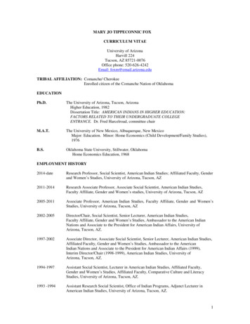
242012 SERVICE 85-52931. Outer Casting TA NB - Black1. Outer Casting TA NB - White2. Bushing Kit3. Seal K0036. Crown/Steer/Leg 80/100 Steel6. Crown/Steer/Leg 80/100 BlkCrwn6. Crown/Steer/Leg 80/100 WhtCrwn7. Preload Adjuster8. Ride Kit – Soft – 80/1008. Ride Kit – Medium – 80/1008. Ride Kit – Firm – 80/1009. Compression Rod141-27220-K005A5. Absolute DamperHGDDDB141-27220-K001141-26532-K0064. Rebound Damper AssemblyKEEE141-23994-K015141-23994-K016Kit Group1. Outer Casting QR NB - WhitePart Number1. Outer Casting QR NB - BlackPart DescriptionCircus Comp Exploded View
2012 SERVICE 177-K001Kit Group1. Compression Rod 80/1001. Compression Rod 1302. Ride Kit – Soft – 80/1002. Ride Kit – Medium – 80/1002. Ride Kit – Firm – 80/1002. Ride Kit – Soft - 1302. Ride Kit – Medium - 1302. Ride Kit – Firm - 1303. Air Preload Cap4. Crown/Steer/Leg 80/100 BlkCrwn4. Crown/Steer/Leg 80/100Wht Crwn4. Crown/Steer/Leg 130 BlkCrwn4. Crown/Steer/Leg 130 WhtCrwn5. Absolute Damper6. Rebound Damper 80/1006. Rebound Damper 1307. Seal Kit8. Bushing Kit9. Outer Casting QR NB Black9. Outer Casting QR NB White9. Outer Casting TA NB Black9. Outer Casting TA NB White10. Knob KitEEEEEIGGGGHHPart K006141-23998-K009141-23992-K002Part DescriptionCircus Expert Fork Schematic
262012 SERVICE MANUAL2141-28131 -K 007141-28131 -K 005141-28131 -K 008141-28131 -K 006141-28131 -K 011141-28131 -K 009141-28131 -K 012141-28131 -K 010141-28131 -K 017141-26532 -K 010141-28131 -K 018141-27988 -K 018141-27988 -K 017141-27988 -K 020141-27988 -K 019141-28131 -K 016141-28131 -K 02485-596 485-529 3141-28131 -K 013141-28131 -K 014141-28131 -K 015141-27988 -K 0131. C row n/S teer/A ssem bly, 1 1/8 S teer, 100m m , B lk C rw n1. C row n/S teer/A ssem bly, 1 1/8 S teer, 100m m , W ht C rw n1. C row n/S teer/A ssem bly, 1 1/8 S teer, 120m m , B lk C rw n1. C row n/S teer/A ssem bly, 1 1/8 S teer, 120m m , W ht C rw n1. C row n/S teer/A ssem bly, T aper S teer, 100m m , B lk C rw n1. C row n/S teer/A ssem bly, T aper S teer, 100m m , W ht C rw n1. C row n/S teer/A ssem bly, T aper S teer, 120m m , B lk C rw n1. C row n/S teer/A ssem bly, T aper S teer, 120m m , W ht C rw n2. K nob K it3. A bsolute D am per A ssem bly4. R ebound D am per A ssem bly5. O uter C asting, Q R N B , B lack5. O uter C asting, Q R N B , W hite5. O uter C asting, Q R 15 N B , B lack (Q R 15 axle included)5. O uter C asting, Q R 15 N B , W hite (Q R 15 axle included)6. Q R 15 A xle7. Q R 15 A xle H ardw are (insert & endcap)8. B ushing K it9. S eal K it10. C om pression R od A ssem bly, 100m m10. C om pression R od A ssem bly, 120m m11. A ir P iston12. A ir C ap6P art N u m b erP art D escrip tio n5DDDDDDDDIABEEEEEEEKHHGC7K it G ro u p4Marvel Expert Fork Schematic38291101112
2012 SERVICE MANUAL27261 4 1 -2 8 1 3 1 -K 0 0 71 4 1 -2 8 1 3 1 -K 0 0 51 4 1 -2 8 1 3 1 -K 0 0 81 4 1 -2 8 1 3 1 -K 0 0 61 4 1 -2 8 1 3 1 -K 0 1 11 4 1 -2 8 1 3 1 -K 0 0 91 4 1 -2 8 1 3 1 -K 0 1 21 4 1 -2 8 1 3 1 -K 0 1 01 4 1 -2 8 1 3 1 -K 0 1 71 4 1 -2 6 5 3 2 -K 0 0 91 4 1 -2 8 1 3 1 -K 0 0 31 4 1 -2 8 1 3 1 -K 0 0 41 4 1 -2 8 1 3 1 -K 0 0 11 4 1 -2 8 1 3 1 -K 0 0 28 3 -3 2 8 31 4 1 -2 8 1 3 1 -K 0 1 61 4 1 -2 8 1 3 1 -K 0 2 41 4 1 -2 7 9 8 8 -K 0 1 81 4 1 -2 7 9 8 8 -K 0 1 71 4 1 -2 7 9 8 8 -K 0 2 01 4 1 -2 7 9 8 8 -K 0 1 98 5 -5 9 6 48 5 -5 2 9 31 4 1 -2 8 1 3 1 -K 0 1 31 4 1 -2 8 1 3 1 -K 0 1 41 4 1 -2 8 1 3 1 -K 0 1 51 4 1 -2 7 9 8 8 -K 0 1 31 . C ro w n /S te e r/A s s e m b ly , 1 1 /8 S te e r, 1 0 0 m m , B lk C rw n1 . C ro w n /S te e r/A s s e m b ly , 1 1 /8 S te e r, 1 0 0 m m , W h t C rw n1 . C ro w n /S te e r/A s s e m b ly , 1 1 /8 S te e r, 1 2 0 m m , B lk C rw n1 . C ro w n /S te e r/A s s e m b ly , 1 1 /8 S te e r, 1 2 0 m m , W h t C rw n1 . C ro w n /S te e r/A s s e m b ly , T a p e r S te e r, 1 0 0 m m , B lk C rw n1 . C ro w n /S te e r/A s s e m b ly , T a p e r S te e r, 1 0 0 m m , W h t C rw n1 . C ro w n /S te e r/A s s e m b ly , T a p e r S te e r, 1 2 0 m m , B lk C rw n1 . C ro w n /S te e r/A s s e m b ly , T a p e r S te e r, 1 2 0 m m , W h t C rw n2 . K n o b K it3 . C a rtrid g e A b so lu te D a m p e r A s s e m b ly4 . C a rtrid g e T u b e , 1 1 /8 S te e r, 1 0 0 m m4 . C a rtrid g e T u b e , 1 1 /8 S te e r, 1 2 0 m m4 . C a rtrid g e T u b e , T a p e r S te e r, 1 0 0 m m4 . C a rtrid g e T u b e , T a p e r S te e r, 1 2 0 m m5 . C a rtrid g e R e b o u n d D a m p e r A s s e m b ly6 . Q R 1 5 A xle7 . Q R 1 5 A xle H a rd w a re (in s e rt & e n d ca p )8 . O u te r C a s tin g , Q R N B , B la c k8 . O u te r C a s tin g , Q R N B , W h ite8 . O u te r C a s tin g , Q R 1 5 N B , B la c k (Q R 1 5 a xle in c lu d e d )8 . O u te r C a s tin g , Q R 1 5 N B , W h ite (Q R 1 5 a xle in c lu d e d )9 . B u sh in g K it1 0 . S e a l K it1 1 . C o m p re s s io n R o d A s s e m b ly, 1 0 0 m m1 1 . C o m p re s s io n R o d A s s e m b ly, 1 2 0 m m1 2 . A ir P is to n1 3 . A ir C a p5P a rt N u m b e rP a rt D e s c rip tio nDDDDDDDDIAAAAABEEEEEEEKHHGCK it G ro u pMarvel Pro Fork Schematic748391021111213
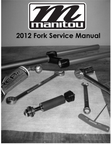
282012 SERVICE 6141-27181-K003141-27181-K0048. Ride kit – Soft - 1308. Ride Kit – Medium - 1308. Ride Kit – Firm – 1309. Compression Rod 80/1009. Compression Rod 005KBADDCGGGEEEEEKit Group5. Absolute Damper6. Crown/Steer/Leg 80/1006. Crown/Steer/Leg 1307. Preload Adjuster8. Ride Kit – Soft – 80/1008. Ride Kit – Medium – 80/1008. Ride Kit – Firm – 80/1003. Seal Kit4. Rebound Damper 141-27181-K0011. Outer Casting QR NB White2. Bushing KitPart rt Description1. Outer Casting QR STD Black1. Outer Casting QR STD White1. Outer Casting QR NB BlackMatch Exploded View
2012 SERVICE MANUAL29Kit -K002141-26532-K0022. Ride Kit – Firm 80/1002. Ride Kit
2012 SERVICE MANUAL 1. From the left leg dropout (Left when sitting on the bike), use a 10 or 11mm wrench to remove the compression rod screw. (Fig. 1) 2. From the right leg dropout, if the fork has adjustable re-bound, the knob will need to be removed. Screw the rebound a