Transcription
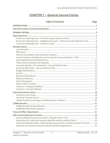
N Gauge Society Journal 1/17LANGSTONBRIDGEBy Julian ThornhillHow does an N gauge modeller, and I use modeller in the loosest possiblesense of the word, who lives in the Midlands miles from the sea end upconstructing a full length scale model of a coastal railway bridge? Well, I holdDapol and a South African resident jointly responsible. . . . .A few years ago now Dapol started tomanufacture a rather fine, dare I say cute, Ngauge model of the Terrier tank locomotive.Having purchased a few I started to cast aroundfor inspiration for a relatively simple layoutproject on which to run them. A photograph ofNorth Hayling station, which is little more thana small platform and a shelter, and thesurrounding easy to model landscape seemedjust the thing.I forget the exact circumstances but Iended up discussing this minor little projectonline with a fellow modeller who is nowresident in South Africa. She said she used tolive in the area and had travelled the line as achild. She then asked if I had consideredbuilding the bridge as well. At that point I hadno idea that there even was a bridge, so Ithought how hard can that be?As a result I started to trawl the Internet forphotographs of the bridge and any other relevantinformation that I could find. The first fewpictures were only ever of part of the bridge, sothe task didn’t seem that hard and I carried ongathering pictures and getting ever more drawninto the project.It was never entirely obvious what theprecise dimensions of the bridge were, and eventhe basic construction was not at all clear as manyof the photographs were taken from angles thatcreated confusing images of the structure underthe bridge deck. A breakthrough occurred whenI came across the Hayling Island online forum. Ioutlined my project in their local history subforum and appealed for any photographs thatmembers might have.A forum member suggested I contact AlanBell, a local railway enthusiast, photographer andPage 44
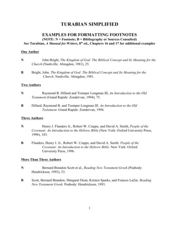
Photograph by Grahame Hedgesauthor. It transpired that he had built OO modelsof many sections of the line over the years, withthe layout ending up in Havant museum. A phonecall revealed that he had crawled all over theclosed bridge with a tape measure and hadproduced scale drawings of pretty much all ofthe structure, including the swing bridge and itscontrolling signal cabin. Furthermore, he kindlysent me a copy of the plans and some additionalphotographs that I had not come across. Mindyou, he did think I was quite mad trying to buildthe bridge in N, though he expressed thissentiment in the politest of terms (A model ofthe line by Stephen Ash was featured in Journal5/01 although only one photograph waspublished - editor).Now the project had started to gain a bit ofmomentum, and having asked for information inpublic, it was increasingly difficult not tocontinue. Having obtained the scale drawings, itwas now a simple task to calculate some basicdimensions of the layout. I was keen to constructthe whole bridge, rather than a shortened versionand was therefore relieved to discover it wasaround 7 feet long in N and not twice that. I couldaccommodate a layout up to 12 feet in my railwayroom, so there was room for a small amount of thebridge approaches and some sharp hidden curvesat either end.As a consequence of my appeals forinformation on the Hayling forum I was approachedby the organiser of the Hayling Billy (this being thelocal name for the train service) 50 celebrations. Ittranspired that 2013 was going to be the halfcentury since the line’s closure and various localexhibitions including a model railway show wereplanned. Could I bring my bridge along please? I’dnever exhibited anything before and hadn’t even
N Gauge Society Journal 1/17Photograph by Grahame Hedgesstarted my model. However, I did have threeyears to the deadline, so it seemed possible - Ihad reached the point of no return.Having the constraints of getting the layoutto an exhibition I needed a baseboard that wouldfit in my admittedly reasonably spacious estatecar. A tape measure revealed that three four bytwo foot boards would fit, provided the boardscould be stacked in the car. This would give mea twelve by two foot layout, which seemed to bejust about right. I could have spent timeperfecting my carpentry skills but would thenhave no time to build my bridge, so I decided tobuy my way out of trouble. Model RailwaySolutions of Poole provided me with what wasneeded – boards, stacking frame and legs - at avery reasonable price.Having now attended three exhibitions, Icannot recommend their system highly enough.All three boards in their stacking carrier are lightenough for two people to carry with ease andeverything bolts together in perfect alignment ina few minutes. A far better system than anythingI was ever likely to produce.As I wanted to construct at least some ofthe approaches to the bridge I decided upon asite visit. Online photographs indicated thatmuch of the original approaches still existed,indeed most of the original track bed has beenretained as a cycle path. A family trip ensued andI spent an afternoon photographing the bridgeremains and the surroundings.The concrete piers are still present and thebridge approaches are in relatively goodcondition. Surprisingly, the metal supports forthe swing bridge are still there after 50 years andit is quite easy to imagine the missing woodenparts of the bridge. The indestructible concretepiers and modern technology combined toprovide even more assistance. The piers arehighly visible on Google Earth aerialphotography, and knowing their dimensionsfrom Alan Bell’s plans it is straight forwards toscale the photographs and work out the exactposition of each pier.This revealed what I had started to suspectfrom my site visit, that the bridge is not straight.The first half from the mainland to the swingbridge is indeed straight, but the second half iscurved. The other dawning truth was that therewere 50 piers, which meant 50 sets of verticalsupports would have to be constructed.A further consideration was what shouldthe bridge be made from? The original waswood, and so was Alan Bell’s OO model. Thestructure of the bridge also has strongsuggestions of matchsticks. The major problemwith using wood on such a small scale is that ofdimensional stability. I might have a nicelyconstructed bridge one day, and a warpedPage 46
twisted mess a few months later. Eventually Isettled upon plastic styrene strip from Plastruct.This comes in a huge range of sizes, being idealnot only for both the major bridge supports butalso for the bridge deck planking and even theslender handrails. It is also easy to cut and canbe glued by a quick setting solvent. Perhaps theonly downside is the cost – I must have spentseveral hundreds of pounds on the product bythe end of the project.To construct 50 sets of identical bridgesupports I built a jig. This consisted of a smallblock of aluminium with slots milled out for thePlastruct strips. The strips could be slid into theslots and glued at the joints. I also invested in asmall guillotine with adjustable stops, so that thestrip could be cut quickly and accurately to tolength.Before I embarked upon full massproduction I built a small section of the bridge,consisting of two piers and vertical supports,together with the bridge deck, handrails, a shortlength of Peco track and a Terrier on top. Thisimmediately showed an unexpected problem –the track. The track and sleepers looked overscale and out of place.Closer examination of the photographsshowed that the track was non standard. Theload bearing sleepers ran under and in the samedirection as the rails, with small lateral spacerbeams every few feet, very similar to Brunel’sbroad gauge track but at standard gauge. Thesolution was to make from scratch. The woodenparts are again Plastruct and the rail is code 40,purchased from the 2mm Society. The rail isattached to the wooden support beam, whichruns parallel to and directly under the rail, bychairs. These, again, came from the 2mm ScaleAssocoiation, as sprues intended for one of theirpoints kits. Unfortunately, I needed about 1000chairs, with each one having to be threaded ontothe rail, accurately spaced and then glued down.It is going to be a long time before I embark onconstructing hand built track again.Several months later I had 50 vertical bridgesupports constructed. But they are not all that isrequired – there is also the swing bridge and itsassociated signal box. I’ve been frequently askedif the bridge actually opens, and in the interestsof accuracy it doesn’t. Fortunately, in the latteryears of the bridge’s existence the swing bridgewas not operational. There are photographs oflocal yachtsmen having to capsize their boats byninety degrees and swimming their boatsthrough simply to avoid entangling the mast withthe bridge.Having neatly sidestepped the need to builda working mechanism there was still a lot of workneeded to accurately reproduce both the swingbridge and the signal box. It is all scratch built,with quite a few hours spent cutting and gluingvarious bits of plastic, but made easier by havingthe proper dimensioned plans mentionedearlier. The swing bridge also makes a naturalpoint at which to divide the model bridge in twofor ease of transport, a seven foot model notbeing that easy to handle.These is a mismatch in that the baseboardscome in three equal four foot lengths while thebridge divides in two at the middle. So how is itall dismantled for transport? Magnets are theanswer. The bridge is held down to the concretepiers by a plug and socket arrangementconstructed from small circular magnets.The concrete piers are modelled from balsawood strips, which are glued to the baseboard.Where the two wooden verticals originally roseout of the concrete I have drilled two small holesand glued in place a 3mm diameter neodymiummagnet. The magnets sit at the bottom of arecessed socket and are about 2mm from thetop. On the wooden bridge supports I have glued2mm diameter magnets and these act as a pinof a plug and fit into the holes in the piers. Using2mm diameter magnets and a 3mm hole allowsa small amount of slop to aid alignment.The magnets are extremely powerful andmake for a very effective joint. However, theyUsing Super-glueIused cyanoacrylate adhesive (CAA), probably better known as super-glue for gluing the magnetsin place. Before embarking on this project I never had much luck with this type of glue, agreeingwith the common refrain that it stuck fingers effectively but not much else. By chance I met theowner of a specialist adhesive manufacturing company, Bondchem, who explained that therewere various grades of CAA, with much of what is available to the consumer being made of cheapraw materials in the far east. He sent me a pack of his product and the difference between thatand the consumer adhesives I had previously used was huge. I’ve taken to gluing many things onmy railway with a drop of this adhesive applied with the tip of a cocktail stick. So, if you’ve beencursing the super glue purchased in a pound shop try some of the more exotic expensive products– there is a real difference.
N Gauge Society Journal 1/17The History of Langston BridgeLangston Bridge connected Hayling Island with the mainland. Hayling Island lies on the south coastof England, a few miles to the east of Portsmouth and is separated from the mainland by a narrowstrip of water approximately 1000 feet wide.The island was first connected to the mainland by a frail road bridge in 1824. In 1859 the Londonand South Western Railway reached Havant, the nearest town to Hayling Island on the mainland.Local business interests formed the Hayling Railway Company in 1860 with a view to constructing abranch line from Havant to Hayling, the main settlement on the southern end of the island.Construction funds were in short supply and much of the route was across difficult terrain on theisland so the bridge across the water to the mainland village of Langstone was built as cheaply aspossible. Note that although the village name is spelt with an ‘e’, while the station serving thecommunity and the the railway bridge have always lacked this final letter – perhaps another minoreconomy measure by the railway?In 1867, after a few false starts, the line finally opened to passenger traffic. The railway bridgeran roughly parallel to the existing road bridge and was of very similar wooden construction. Bothbridges featured a swing bridge in their centre to allow for the passage of local boats. As alreadymentioned, the road bridge was a flimsy affair, with the maximum permitted vehicle weight a shadeover six tons. Until its replacement in 1956 buses were limited to no more than 13 passengers, anymore than this being forced to walk across. Although the newer railway bridge was more substantial,it too was subject to a relatively low weight limit which prevented the use of anything heavier thana 28 ton Terrier tank locomotive. Apart from a few obscure locomotive types used in the early years,the Terrier has been the only locomotive type used right up until the line’s closure.Originally the bridge was entirely of wooden construction but it was soon found that the tidalcurrents were damaging the vertical underwater supports. The problem was solved by encasing thesupports in concrete up to the high water mark. The concrete structures proved to be extremelystrong and remain in place to this day. When the bridge was demolished attempts were made toremove the concrete piers by the use of explosives but this proved to be entirely unsuccessful leavingonly minor damage to two supports.The approximately ten mile single track branch ran an intensive service, latterly serving holidaytraffic as Hayling Island developed into a popular seaside destination. The bridge, however, was tobe the line’s undoing. By 1963 the bridge was in need of expensive repair, and despite the lineoperationally breaking even it fell victim to the then current fashion of closing branch lines. The finaltrain ran in November 1963 and the bridge was demolished in 1966.This photograph by Grahame Hedges, all remaining photos (on pages 49 & 50) are by Julian ThornhillPage 48
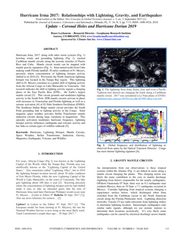
are pulled apart reasonably easily, makingit simple to lift the bridge from thebaseboard. For transportation I obtained along thin cardboard box and stuck a thinsteel plate inside the box. The bridge simplysticks to the plate with its magnets insidethe box.The bridge deck is also constructedwith Plastruct. I laid every single deck plankas an individual plastic strip as I could seeno other way to obtain a pleasingrepresentation of a planked deck. Once thedeck was in place I ended up with a longthin bridge like structure, but in gleamingwhite. Next was to make it look like awooden bridge.After a bit of experimentation, I foundthat painting the different surfaces inslightly different shades of brown gave arealistic effect. Therefore, the verticalsupports are a different shade to the bridgedeck and the deck top is lighter than thedeck underside. I used matt acrylic paintapplied with an airbrush. However, I’dnever used an airbrush before, and despitereading a lot on the subject I decided Ineeded someone to teach me how to useone. I found that Hobby Holidays offersweekend courses and booked myself ontothe beginners course. I became an expertat painting empty dog food tins, this beingthe preferred learning aid.Next to tackle was modelling thewater. Fortunately there are no greatwaves around the bridge, the area being analmost enclosed sheltered body of water.Also, the sea is not bright blue, it not beingthe brilliantly lit Mediterranean. In the endI painted the baseboard a grey blue andadded patches of slightly more intense bluewith the air brush. This represents thepatchy cloud covered illumination that isoften found on the south coast. I thenapplied six coats of cheap Wilko acrylicvarnish which creates a pleasing wateryreflective effect.The back-scene is probably the part ofthe layout that has given me the mostpause for thought. The background of theprototype is just sky in the distance. Myback-scene is just a few inches behind thebridge, the baseboard being only two feetwide. Back-scenes with a bright blue skywith white fluffy clouds rarely look right,especially when they are not several feetin the distance. In the end I plumped for aplain blue grey card, in an attempt not todraw attention away from the bridge to aAbove : The bridge supporting concrete pier remnants.Above : The remains of the bridge swing mechanismprotective bulwark and support. Below : Building andtesting the hand-built track for the bridge.
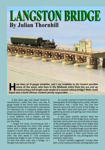
N Gauge Society Journal 1/17Above : The test build section of the bridge.Above : Trial running over the completed and painted bridgealthough not yet located on the piers. Below : The landareas and sea take shape as the layout nears completion.Page 50poorly executed sky representation.The reaction to this at exhibitions isroughly split half and half betweenthose think it is exactly the rightapproach and those who think I needa better back-scene.Operationally, the layout is verysimple, being just a large oval of track.At each end of the bridge the trackdisappears through a hole in the backscene and returns at the back of thelayout. I’ve broken the track supplyinto two regions, the visible and thehidden areas. The hidden area sectionis fed with one DC controller and thevisible with another. The controllers’speeds are set such that the train runsslowly across the bridge and thenraces round the back, ready to crossthe bridge again as quickly as possible.This keeps a moving train in view forthe audience for as long as possibleand keeps people’s attention atexhibitions.The layout had its first outing atHayling Island, this being the first evershow that I’ve exhibited at. I wassomewhat apprehensive about thereception I might receive, given thatthe audience was a mixture of railwaymodellers and locals who know thearea. Happily everyone was most kindand complementary, including agentleman who said he used to driveTerriers across the bridge. I’ve sinceexhibited at Bideford, thanks to aninvite from Maurice at Osborn’sModels, and recently at TINGS inLeamington. The latter was a reallynerve wracking experience – yes it ispossible to get stage fright with modelrailways – given the specialistknowledge of the audience and thequality of the other exhibits. However,again everyone was most kind and Ienjoyed the experience once the showgot underway.Finally, I’ve found that the bridgeis very hard to photograph. Yes, it ispossible to capture some fine close upshots, but pictures of the whole bridgejust look like a long thin stick. Lookingat the model in the flesh, so to speak,is quite a different experience. Ihaven’t quite worked out whyperception differs so greatly. This isclearly an excuse for us all to get outto more exhibitions.
and glued in place a 3mm diameter neodymium magnet. The magnets sit at the bottom of a recessed socket and are about 2mm from the top. On the wooden bridge supports I have glued 2mm diameter magnets and these act as a pin of a plug and fit into the holes in the piers. Using 2mm diameter magnets