Transcription
Technical Manual 1Design of Monopole BasesBy Daniel Horn, P.E.
Copyright 2011 by Tower Numerics Inc. All rights reserved.www.towernx.comCare has been taken to ensure that the material found in this publication is both usefuland accurate. However, please be aware that errors may exist in this publication, and thatTower Numerics Inc. makes no guarantees concerning accuracy of the information foundhere or in the use to which it may be put.
ContentsIntroduction1Organization . 1Historical Perspective . 2AISC Method For Building Columns . 7Flexible Base Plate . 8Example 1.1 . 9Stiff Plate Approach . 12Example 1.2 . 14Example 1.3 . 17Grouted Base Plates19Process Equipment Design Method. 19Example 2.1 . 26Lutz Modification . 29Example 2.2 . 31Complete Square Base Plate – Load On Diagonal . 33Modification for Clipped Corners. 36Example 2.3 . 38Example 2.4 . 43Complete Square Base Plate – Load Parallel . 47Example 2.4 . 50Complete Circular Base Plate Method . 54Example 2.5 . 58Ungrouted Base Plates63Determining Bolt Forces . 63Example 3.1 . 64Example 3.2 . 66Example 3.3 . 68Determining Plate Stresses71Introduction. 71Effective Width Based Upon Plate Theory . 71Process Equipment Methods . 72Example 4.1 . 74Base Plates With Gussets. 77Alternate Method 1 . 79Technical Manual 1 Design of Monopole BasesContents iii
Alternate Method 2 . 79Alternate Method 3 . 79Method of Slices. 80Example 4.2 . 83Alternate Method 1 – Square Base Plates. 87Alternate Method 2 – Circular Base Plates . 87Boulos Method (New York Dept. of Transportation) . 87Diagonal Loading Case. 90Parallel Loading Case . 91Owens Method (New York Dept. of Transportation) . 94ASCE Manual 72 (Proposed 2003 Revision) . 95Example 4.3 . 96Anchor Bolts99Material Grades . 99Anchorage . 101Example 4.1 . 103Recommendations105Determining Base Plate Forces . 105Grouted Base Plates . 105Ungrouted Base Plates. 105Determining Base Plate Stresses. 105Construction Details. 107Bibliography108References. 108iv ContentsGlossary of Terms111Index113Technical Manual 1 Design of Monopole Bases
IntroductionOrganizationThe following chapters will cover the following topics:1. An historical perspective including the AISC approach to base plate design for building columns.2. Classical methods for determining bolt forces and concrete stresses for grouted base plates.3. Classical methods for determining bolt forces for ungrouted base plates.4. Evaluation of various methods currently being used to determine base plate bending stresses forplain and stiffened platesTechnical Manual 1 Design of Monopole BasesIntroduction 1
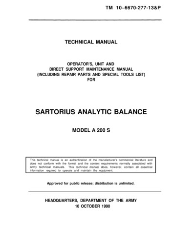
Historical PerspectiveMonopoles have become increasingly popular for use in the telecommunication industry. Theadvantages include architectural attractiveness and a minimal use of land. Poles are of two generaltypes, tapered polygonal poles and stepped pipe poles.The tapered polygonal pole shown in Fig. 1-1, is custom manufactured to exact diameters requiredfor the design. Each section is joined using telescoping lap joints.Fig. 1- 1Technical Manual 1 – Design of Monopole BasesIntroduction 2
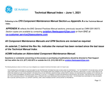
Pipe poles are made from large diameter pipe sections and joined by external or internal flangeconnections as shown in Fig. 1-2.Fig. 1- 2While some poles may be directly buried into the earth, the most common method of attaching thepole to the foundation is with a base plate.Technical Manual 1 Design of Monopole BasesIntroduction 3
Base plates can be square with clustered anchor bolts as shown in Fig. 1-3 when overturningmoments are relatively light.Fig. 1- 3The clear space below the leveling nut is not limited by the TIA-222 Standard; however, the ASCEManual(1) suggests limiting the distance to two bolt diameters. AASHTO(2) limits this distance toone bolt diameter. AASHTO also recommends that the minimum base plate thickness be equal tothe bolt diameter.Technical Manual 1 – Design of Monopole BasesIntroduction 4
Base plates can also be polygonal or circular to accommodate a larger number of bolts. The platemay need to have gusset plates (stiffeners) in order to transfer forces due to axial and bendingmoment to the pole. A typical example is shown in Fig. 1-4.Fig. 1- 4Poles have been used in the power transmision field since the 1960’s. Prior to that, poles were usedalmost exclusively for flags(3,4) and for highway structures(2). In recent years, poles have becomepopular for both electric transmission towers and for telecommunication structures.There is currently no industry standard for the design of pole base plates. Some state highwaydepartments (New York) have developed their own methods, but no national standard exists. Assuch, the designer is left to arrive at appropriate methods based upon classical structuralmechanics. While some testing has been done on smaller pole base plates used in highwayconstruction (usually poles between 10 and 20 inches in diameter), no testing has been done onlarger diameter pole base plates such as used in the telecommunication industry (poles 36 to 72inches in diameter). Therefore, such design techniques may or may not be appropriate. Recent finiteelement studies(5,6,7) have indicated that current design practices used by pole manufacturers maybe under-designed by 20 to 30%.Technical Manual 1 Design of Monopole BasesIntroduction 5
Although monopole failures are a relatively rare occurrence, a number of recent pole failures (seeFig. 1-5) have increased interest in manufacturer’s design and manufacturing techniques.Fig. 1- 5The purpose of this report is to make available the various design techniques currently being usedin the industry in the hope that more reliable methods of design may be developed in the future.To begin, let us examine the traditional methods that have been developed for designing buildingcolumns subject to axial loads and moment.Technical Manual 1 – Design of Monopole BasesIntroduction 6
AISC Method For Building ColumnsMoment resisting base plates for building columns are covered in neither the AISC Specificationnor the Manual of Steel Construction. Engineers must therefore refer to textbooks or technicalpapers for design methods although not all texts cover this topic.Working stress methods for analyzing moment resistant base plate can be found in engineeringtexts(8,9,10,11,12). DeWolf(13) and Thambiratnam(14) compared methods of designing building columnsto test data.The AISC method for designing axially loaded base plates defines the critical section as being at .95times the depth of the structural members for shapes of rectangular cross-section such as wideflanges and tubes. The critical section for pipe is defined at a location equal to .80 times thediameter of the pipe.Two different approaches have been taken to determine the distribution of forces on the base plate,a flexible plate approach and a stiff plate approach.Technical Manual 1 Design of Monopole BasesIntroduction 7
Flexible Base PlateRelatively flexible base plates are incapable of maintaining a linear strain distribution and theassumption is made that the compression force is centered beneath the compression flange of thecolumn.PMfDTCfcA/3AN'NFig. 1- 6 Flexible base plate force distributionThe following basic equations (B plate width) define the static forces as shown in Fig 1-6.T P C fcAB2PD2T Df 22 (T P )fc ABM Technical Manual 1 – Design of Monopole BasesIntroduction 8
Example 1.1Design a base plate for an axial load of 60 kips and a moment of 480 in-kips. Fy for the plate andanchor bolts is 36 ksi and f’c is 3 ksi. The structural member is an 8-inch wide flange and the baseplate is 14x14. The bolts are 1.5” from the edge.60 k480 in-k5.5"8"TCfcA/3AN' 12.5"N 14"Fig. 1- 7Technical Manual 1 Design of Monopole BasesIntroduction 9
Fp .35fc′A2 .70fc′ 2.1 ksiAp60 82 25.26 kips 12.63 kipsT bolt85.5 214 8 9A 3 2C T P 25.26 60 85.26480 fc 2 (85.26) 1.35 ksi 2.1 ksi o.k.9 14The thickness of the plate is determined by checking both the compression and tension sides. Thecritical section is at14 0.95 8 3.2 in29 3.2fcpl 1.35 0.87 ksi920.87 3.22 (1.35 0.87 ) 3.2in kipM pl 6.09 in232M W t plS reqd , W 1" Fb6b t pl 6MFbFb .75Fyt pl 6 6.09 1.16 in.75 36Technical Manual 1 – Design of Monopole BasesIntroduction 10
The critical width on the tension side is defined by AISC as shown in Fig 1-8.14"beffb 3.2"14"45 1.5"1.5"8"Fig 1-8M pl 12.63 (3.2 1.5) 21.47 in kips3.2 1.5 1.7 1.5 use 1.5beff 1.5 (3.2 1.5) 3.2 int pl 6 21.47 1.22 in 1.163.2 .75 36Therefore the tension side controls.Technical Manual 1 Design of Monopole BasesIntroduction 11
Stiff Plate ApproachThicker, stiffer, base plates are capable of approaching a linear strain distribution and the base plateis assumed to behave in a manner similar to reinforced concrete columns(8).PMfDfcTAN'NFig 1- 9 Stiff base plate force distributionThe following basic equations define the static forces as shown in Fig 1-9.P T C fcAB2where B width of the base plate.e MP N A e T P 2 3 NA f 2 3 Technical Manual 1 – Design of Monopole BasesIntroduction 12
fc TA N A s n A f 2 P T TA2 B N 2A s n A f 2 Defining N K1 3 e 2 6nA sK2 (f e)B N K 3 K 2 f 2 A 3 K1A 2 K 2A K 3 0Technical Manual 1 Design of Monopole BasesIntroduction 13
Example 1.2Design the same plate of Example 1.1 using the stiff approach and assuming 1 ¼” diameter bolts.Fp .35fc′A2 .70fc′ 2.1 ksiAp480 8 in6029000n 9. 357 3000A s 2 .969 1.94e 14 K1 3 8 3 2 6 9.3 1.94K2 (5.5 8) 10414 14 K 3 104 5.5 1300 2 Solving for A by trial,A 7.3 in 7.3 8 7 20.5 kips 10.25 kips3T 60 bolt 7 7.3 5.5 3 20.5 7.3 1.6 ksi 2.1 ksifc 9.3 1.94 (7 7.3 5.5)Technical Manual 1 – Design of Monopole BasesIntroduction 14
The thickness of the plate is determined by checking both the compression and tension sides. Thecritical section is at14 0.95 8 3.2 in27.3 3.21.6 0.90 ksifcpl 7.320.90 3.22 (1.6 0.90) 3.2 M pl 7 in inkip236 7t pl 1.25 in.75 36b The critical width on the tension side is defined by AISC as shown in Fig 1-10.14"beffb 3.2"14"45 1.5"1.5"8"Fig 1-10Technical Manual 1 Design of Monopole BasesIntroduction 15
M pl 10.25 (3.2 1.5) 17.43 in kips3.2 1.5 1.7 1.5 in side clearanace use 1.5 inbeff 1.5 (3.2 1.5) 3.2 int pl 6 17.43 1.10 in 1.25 in3.2 .75 36Therefore the compression side controls.Technical Manual 1 – Design of Monopole BasesIntroduction 16
Example 1.3Re-design Example 1.2 for an 8” pipe column. A pipe would have the critical section defined as14"b 3.2"beff45 14"1.5".8xDiameter1.5"Fig 1-11The analysis for bolt forces and concrete stress are identical to the wide flange base plate, howeverthe distance to the critical section is now14 0.80 8 3.8 in27.3 3.81.6 0.77 ksifcpl 7.320.77 3.82 (1.6 0.77 ) 3.8 M pl 9.55 in inkip236 9.55t pl 1.46 in.75 36b Technical Manual 1 Design of Monopole BasesIntroduction 17
Checking the tension sideM pl 10.25 (3.8 1.5) 23.58 in kips3.8 1.5 2.3 1.5 in side clearance use 1.5 inbeff 1.5 2.3 3.8 int pl 6 23.58 1.17 in 1.46 in3.8 .75 36Therefore the compression side controls.Technical Manual 1 – Design of Monopole BasesIntroduction 18
Grouted Base PlatesProcess Equipment Design MethodProcedures for designing circular base plates with large openings (approaching the inner diameterof the shell) have been used for over 75 years. The most common use has been for chimneys andstacks used in the process equipment field. The method most often used was based upon the workof Taylor, Thompson, and Smulski(15). The following description of the method is taken fromBrownell and Young(16), Troitsky(17), Megyesy(18), and Bednard(19). The method was developed forcircular base plates; however the method can be conservatively used for polygonal plates andsquare base plates by using the diameter across the flats of the plate. The method is based uponreinforced concrete column theory using the Working Stress Design Method (WSD). Note that allof the grouted base plate techniques that follow assume that the eccentricity is sufficiently largeenough to produce tension on a portion of the base plate.MPfsnfckd(d-kd)dFig. 2- 1Technical Manual 1 Design of Monopole BasesGrouted Base Plates 19
Defining the modular ratio asn EsEcFig. 2-1 is a sketch representing the loading condition for the anchor bolts of the monopole baseplate. The method assumes that the bolt circle is in the center of the bearing plate, which is typicallythe case when the shell of the pole runs through the base plate. The wind load and the dead weightload of the pole result in a tensile load on the upwind anchor bolts and a compressive load on thedownwind anchor bolts. Denoting fc as the compressive stress in the concrete, the inducedcompressive stress in the steel bolts is given byfs nfcConsidering the stress to be directly proportional to the distance from the neutral axis, a straightline may be drawn from fs to nfc as shown in Fig. 2-1. The neutral axis is located at a distance kdfrom the downwind side of the bearing plate and at a distance (d – kd) from the upwind side. Thisassumption is valid only if the base plate can be considered rigid.By similar trianglesfsnf c(d kd) kdthereforek nfc1 nfc fs 1 fsnfc( )The area of bolts can be expressed in terms of an equivalent ring of steel of thickness t having thesame total cross-sectional area of steel as shown in Fig. 2-2. This assumption would only be valid ifthere are a sufficient number of bolts uniformly spaced around the bolt circle. Polygonal plates canbe assumed to be a circular ring equal to the flat diameter of the polygon.Technical Manual 1 – Design of Monopole BasesGrouted Base Plates 20
tstcδθαθFtNeutral axisFcd/2r kdFtl1l2jdzdFcFig. 2- 2The location of the neutral axis from Fig. 2-2 can be defined in terms of the angle α.cos α d 2 kd 1 2kd2Andα cos 1 (1 2k )A differential element of the steel ring is measured by dθ. The area of this element isdA s t s rdθTechnical Manual 1 Design of Monopole BasesGrouted Base Plates 21
wherer d 2The distance from the neutral axis to this differential element isr(cos α cos θ )Denoting the maximum steel stress as fs, the stress in the element isfs′ fsr (cos α cos θ)r (1 cos α )The force in the element is thereforedFt dA s fs′ fs t s r(cos α cos θ)(1 cos α )The total tensile force is thereforeπFt 2 dFt 2fs t s r απα(cos α cos θ)dθ(1 cos α ) 2 fs t s r ((π α ) cos α sin α ) (1 cos α ) fs t s rC twhere 2C t ((π α ) cos α sin α ) (1 cos α ) The c.g. of the tensile force, l1, can be located by first determining the moment on the tension sideand then dividing by Ft. The moment of the differential element isdM t dFt r ( cos α cos θ) (cos α cos θ ) fs t s r r (cos α cos θ) dθ 1 cos α (cos α cos θ )2 dθ fs t s r 1cos α() IntegratingM t 2fs t s r2 πα2(cos α cos θ)dθ(1 cos α ) (π α ) cos2 α 23 (sin α cos α ) 21 (π α ) 2fs t s r2 1 cosα Technical Manual 1 – Design of Monopole BasesGrouted Base Plates 22
Dividingl1 (π α ) cos2 α 23 (sin α cos α ) 21 (π α ) Mt r Ftcossinπ αα α() The values of α, Ct and l1 are constants for a given value of k.Values for the compression area follow a similar formulation. The width of the compression ring isdefined as t c bpl t s . The differential element for a compression ring of thickness tc isdA c t c rdθThe distance from the neutral axis to this element isr (cos θ cos α )The maximum distance from the neutral axis isr (1 cos α )The element stress is directly proportional to the distance from the neutral axisfc′ fcr (cos θ cos α )r (1 cos α )The compressive stress in the steel isfsc′ nfc(cos θ cos α )(1 cos α )The force is determined by multiplying by the element areas cos θ cos α dFc fc′dA c fc t c r dθ 1 cos α cos θ cos α dFsc nfsc′ dA s nfc t s r dθ 1 cos α The total is therefore cos θ cos α dFctot (t c nt s ) rfc dθ 1 cos α Integratingcos θ cos αdθ01 cos α 2 (sin α α cos α ) Fc (t c nt s ) rfc 1 cos αFc (t c nt s ) rfc 2 αFc (t c nt s ) rfc C cConverselyTechnical Manual 1 Design of Monopole BasesGrouted Base Plates 23
fc Fc(t c nt s ) rC cWhere sin α α cos α Cc 2 1 cos α The c.g. of the compressive force, l2, can be located by first determining the moment on thecompression side and then dividing by Fc. The moment of the differential element isdM c dFc r (cos θ cos α )2(cos θ cos α ) (t c nt s ) r fcdθ(1 cos α )2IntegratingM c (t c nt s ) fc r 2 2α2(cos θ cos α )dθ1 cos α231 2 cos α 2 (sin α cos α ) 2 α (t c nt s ) fc r 2 1 cos α 0Dividing α cos2 α 23 (sin α cos α ) 21 α Mc l2 r Fcsincosα αα The total distance between the forces Ft and Fc is equal to l1 l2. Defining the dimensionless ratio j asl1 l 2d23 (π α ) cos2 α 21 (π α ) 23 sin α cos α 1 1 1 2 α 2 sin α cos α α cos α 2 2 sin α α cos α(π α ) cos α sin α j The distance from the neutral axis to the centerline of the pole isdcosα2and the distance zd is equal tozd l 2 dcos α2The quantity, z is therefore 1 α 23 sinα cos α α cos2 α z 12 cos α 2 α ααsincos Technical Manual 1 – Design of Monopole BasesGrouted Base Plates 24
The values of Cc, l2, j and z are constants for a given value of k.The two equilibrium conditions that must be met areM wind Pzd Ft jd 0M wind PzdjdFt P Fc 0Fc Ft PFt Substituting M Pzd fs 2π wind C jdA ts F tt s rC tfc kdfsn (d kd)The peak bearing stress, at the outer edge of the base plate is 2kd bpl fcmax fc 2kd Where bpl is the width of the bearing plate.Technical Manual 1 Design of Monopole BasesGrouted Base Plates 25
Example 2.1Analyze a grouted base plate for a 55” diameter pole that runs through the base plate. The boltcircle is 64” with (20) 2-1/4” bolts. The vertical load is 46 kips and the moment is 3565 kip-ft (42780in-kips). The thickness of the base plate is 2-1/4”. The outer diameter of the base plate is 73”. Theconcrete has a strength of 3000 psi.n Es29000 9.29E c 57 3000A s 20 (3.25) 65 in 2r ts tc 64 32 in265 .323 in64π73 55 .323 8.6772Assuming a trial value of k of 0.30 α cos 1 (1 2k ) cos 1 (.4) 1.1593 rad (sin (1.1593) 1.1593 cos (1.1593)) 1.5093C c 2 111593 cos.() Ct 2 (π 1.1593) cos (1.1593) sin (1.1593) 2.442 1 cos (1.1593) 1 1.1593 3 sin (1.1593) cos (1.1593) 1.1593 cos (1.1593)2 2 .4376z 12 cos (1.1593) 2 sin (1.1593) 1.1593 cos (1.1593) (π 1.1593) cos2 (1.1593) 21 (π 1.1593) 23 sin (1.1593) cos (1.1593) j 1.1593cos1.1593sin1.1593π ()()() 2 1 1.1593 23 sin (1.1593) cos (1.1593) 1.1593 cos (1.1593) 1 2 .7812 sin1.15931.1593cos1.1593 ()() 12Ft 42780 46 .4376 64 830 kips.781 64Technical Manual 1 – Design of Monopole BasesGrouted Base Plates 26
Fc 830 46 876 kipsfs fc 830 32.88 ksi.323 32 2.442876 1.55 ksi(8.677 9.29 .323) 32 1.5093k calc 1 .30532.881 9.29 1.55Calculate a new value for k,k .3 .305 .30252The next loopα 1.165C c 1.516C t 2.4366z .437j .781Ft 829.8Fc 875.8fs 32.92fc 1.546k calc .303Which is sufficiently accurate to proceed to final calculationsPbolt fsA bolt 32.92 3.25 107 kips 73 55 1.546 2 .3025 64 2 fcmax 1.78 ksi .7 3 1.33 2.8 ksi o.k.2 .3025 64The maximum bending moment in the plate is actually due to a trapezoidal stress distribution,however most process equipment designers use the average stress at the bolt circle for ease ofcomputation. The stress on the compression side isTechnical Manual 1 Design of Monopole BasesGrouted Base Plates 27
in kipfc l2 1.546 92M max 62.622in6M 6 62.6fmax 2 74.2 ksi .75 36 1.33 36 ksi n.g.bt1 2.252The stress on the tension side isM max Pa 107 fmax 64 55 481.5 in kip26 481.5 66 ksi .75 36 1.33 36 ksi n.g.55π22.2520Technical Manual 1 – Design of Monopole BasesGrouted Base Plates 28
Lutz ModificationOne of the major assumptions in the Process Equipment Method is that the center of pressure iscoincident with the steel bolt ring. Should the compression ring extend inside the pole and the boltcircle is not centered on the outstanding leg of the base plate or, based upon the relative stiffness ofthe base plate, it is deemed that the center of compression will be at or near the pole diameter, thenthe results will be in error.Lutz(20) extended the theory to account for the fact that the compression ring may have a differentdiameter than the steel tension ring.tsα1αδθtcθFtFcrc Dc/2roNeutral axisd/2r (d-Dc)/2kdFtjdzdFcFig. 2- 3Lutz observed that a simple correction using two values of k would yield the correct result.Technical Manual 1 Design of Monopole BasesGrouted Base Plates 29
kt 1 rc rr k c2r" jd" ( j 21 ) d rcFt fc M wind Pzd( j 12 ) d rcFc t nt r r Ccsc c rc 12k 1 r r c1 ( f nf )scThe peak bearing stress, at the outer edge of the base plate, with radius ro , is 2kd ro rc fcmax fc 2kdThe value C c is calculated using k while the values for C t , z and j are then calculated using thevalue of k t . Note that when rc r then k t k and the results are identical to the ProcessEquipment Method.Technical Manual 1 – Design of Monopole BasesGrouted Base Plates 30
Example 2.2Analyze a grouted base plate with an inner diameter of 48” and an outer diameter of 73”. The boltcircle is 64” with (20) 2-1/4” bolts. The vertical load is 46 kips and the moment is 3565 kip-ft (42780in-kips). The thickness of the base plate is 2-1/4”. The concrete has a strength of 3000 psi.n Es29000 9.29E c 57 3000A s 20 (3.25) 65 in 2r rc (73 48) 22ts tc 64 32 in2 30.25 in65 .323 in64π73 48 .323 12.1772Assuming a trial value of k of 0.2773 α cos 1 (1 2 .2773) 1.109 rad (sin (1.109) 1.109 cos (1.109)) 1.447C c 2 cos.11109() kt 1 30.25 3230.25 .2773 .2895232α1 cos 1 (1 2 .2895) 1.1362 radCt 2 (π 1.1362) cos (1.1362) sin (1.1362) 2.4482 1 cos (1.1362) 1 1.1362 3 sin (1.1362) cos (1.1362) 1.1362 cos (1.1362)2 2 .4399z cos (1.1362) 2 sin1.13621.1362cos1.1362()() 12Technical Manual 1 Design of Monopole BasesGrouted Base Plates 31
(π 1.1362) cos2 (1.1362) 21 (π 1.1362) 23 sin (1.1362) cos (1.1362) j 21 π 1.1362cos1.1362 sin1.1362()()() 1 1.1362 23 sin (1.1362) cos (1.1362) 1.1362 cos2 (1.1362) 1 2 .78072 sin1.13621.1362cos1.1362 ()() Ft 42780 46 .4399 64 860.42 kips(.7807 .5) 64 30.25Fc 860.42 46 906.42 kipsfs fc 860.42 33.97 ksi.323 32 2.4482906.42 1.349 ksi 12.177 9.29 .323 32 30.25 1.447 30.25 1 32 30.25 .277k calc 33.771 9.29 1.34912Which is sufficiently accurate to proceed to final calculationsPbolt fsA bolt 33.97 3.25 110.4 kipsfcmax 1.349 2 .2773 32 36.5 30.25 1.70 ksi2 .2773 32Technical Manual 1 – Design of Monopole BasesGrouted Base Plates 32
Complete Square Base Plate – Load On DiagonalThe Process Equipment Method assumes that the bolts can be idealized as a ring of steel and thatthe compression area can be idealized as a ring with the center of pressure at the center of the ring.Often base plates are encountered that have as few as four bolts. These cases can result insignificant errors when calculating pressures and bolt forces. Base plates that extend inside the polewill also have a triangular stress distribution that may differ from the assumed ring theory.Horn(21), developed a method for square base plates with a circular opening which takes intoaccount individual bolt locations. Circular or polygonal plates can be analyzed using the CompleteCircular Base Plate Method discussed in the next section.qBye M/Pn.a.diFig. 2- 4Technical Manual 1 Design of Monopole BasesGrouted Base Plates 33
The method is valid when there is net tension on the section, a condition that occurs whenB4 πd4i 1264e 2 πd2i .707 B B 4 The method will make use of transformed areas of the bolts. Bolts that are in the tension zone willhave their areas transformed byA bolt nA bBolts within the compression zone will have their areas transformed byA bolt (n 1) A bThe method will calculate moment of inertia of the areas and the moment areas about the “e” line .The moment of inertia divided by the moment area will then be the location of the neutral axis. Theprocess iterates on the value of q until it is determined to a sufficient degree of accuracy.Definingdi2y .707 B e qri n 2900057 fc′fc Py maxqA T Q TA T A1 A2 A c comp (n 1) A b tens nA bThe area of the triangular wedge is defined asA1 y 2 y y22Should the neutral axis (n.a.) fall below the diagonal of the plate, two wedge areas will have to besubtractedy2 y .707 BA2 0 if y2 0 2y22 if y2 0Should the neutral axis fall below the top of the circular opening, the area of the semi-circle must bedeductedTechnical Manual 1 – Design of Monopole BasesGrouted Base Plates 34
l ri e qy 0 max (ri l, ri ) y ri2πAc y 0 ri2 y20 ri2 sin 1 0 , l 0 r 2iThe moment area is defined asQ T
Technical Manual 1 Design of Monopole Bases Introduction 3 Pipe poles are made from large diameter pipe sections and joined by external or internal flange connections as shown in Fig. 1-2. Fig. 1- 2 While some poles may be directly buried into the earth, the most common method of a