Transcription
Design and Implementation of aSolar Power System in Rural HaitibyShaheer M. HussamSubmitted to the Department of Mechanical Engineeringin Partial Fulfillment of the Requirements for the Degree ofBachelors of Science in Mechanical Engineeringat theMASSACHUSETTS INSTITUTE OF TECHNOLOGYFebruary 2004 MMIV Shaheer M. Hussam. All rights reserved.The author hereby grants to MIT permission to reproduceand distribute publicly paper and electroniccopies of this thesis document in whole or in part.Author- .------Department of Mechanical Engineering- , , A)January23, 2004Certified byIStephen ConnorsTheSis Supervisor, Laboratory for Energy and the EnvironmentIAccepted byErnest CravalhoChairman, Undergraduate Thesis CommitteeARCHIVESMASSACHUSETTS INSTITtEOF TECHNOLOGYOCT 2 8 2004ILIBRARIES
Design and Implementation of aSolar Power System in Rural HaitibyShaheer M. HussamSubmitted to the Department of Mechanical Engineeringon January 23, 2004 in Partial Fulfillmentof the Requirements for the Degree ofBachelors of Science in Mechanical EngineeringABSTRACTThis paper describes the design and implementation of a solar power system for a school andhealth center in Petit-Anse, Haiti. The end-use applications are lighting via a set of fluorescentand incandescent bulbs, and a coolbox for medical refrigeration at the health center. The power isderived from five 120W photovoltaic BP Solar panel units. The author and colleagues traveled toPetit-Anse in January 2002, and a final implementation plan for the Spring of 2004, describingbudget, team development, and itinerary is described.Thesis Supervisor: Stephen ConnorsTitle: Director, Analysis Group for Regional Electricity Alternativesat the Laboratory for Energy and the Environment2
ACKNOWLEDGEMENTSThe author would like to thank the teachers and students of Development Lab/The HaitiClass (SP.712) for their impressive work in initiating, designing, and operating the course.Special thanks goes first to Amy Smith '84 and Jamy Drouillard G, for being the teachers when Itook the course, and the initial team members: Johanne Blain G and John Pope '03. And a thanksto all the other students in SP.712 for their enthusiastic work for such an important class at MIT.Further thanks goes to Stephen Connors, for his patience in guiding this thesis and hisknowledge on a variety of fascinating energy issues. Thanks also goes to Ed Moriarty for his helpon various thesis issues and in connecting the project with his work at the O'Bryant School.Many thanks to the BP Solar folks who donated their time and resources in getting our team thesolar panels. This project would not have been realistic without their help.Finally, great thanks to everyone in Boston and Petit-Anse that made this project feasibleand worthwhile - Gerty Lahens, Father Valcimond at the monastery, and all our colleagues of theFriends of Petit-Anse cooperative.3
TABLE OF CONTENTSList of Figures51. Introduction.61.11.21.31.4Technical SummaryCommunity OverviewClient SummaryOur Involvement66782. System Components .102.1 PV Modules102.2 Charge controller112.3 Batteries132.5 Balance of System (BOS)133. System Design .3.1 Client Needs13143.2 Project Constraints153.3 Load Calculation3.4 Array Sizing3.5 Battery Sizing1516173.6 Balance of System3.6.1 Panel Mounts17183.6.2Wiring183.6.3 Equipment Housing184. System Implementation .204.1 Funding and Project Costs4.1.1 Funding4.1.2 System Costs4.1.3 Field Costs4.2 Component Acquisition and Transportation4.3 Team Development4.4 Travel Itinerary4.5 Work Ahead and Concluding Remarks20202021212122225. References .246. Appendix .256.1 BP Solar 120S product specifications6.2 Local contacts42526
LIST OF FIGURESIntroductionPage1.11.21.31.478910Map of HaitiGeneral PhotosRoof/Site PhotosLayout of SiteSystem Components2.1 BP Solar 120S Panel2.2 Lighting2.3 Coolbox1112122.4 Charge Controller13System Design3.1 Block Diagram3.2 Client Requirements14143.3 Project Constraints3.4 Load Estimation15163.5 PV Array Sizing163.6 Solaration Map173.6 Battery Array Sizing3.7 Wiring1719Project Implementation4.1 System Costs4.2 Field Costs21214.3 Travel Itinerary225
1.INTRODUCTIONWhat are the possible technologies for producing off-grid electricity in developingcountries? Options include fossil fuel-based technologies such as diesel generators, or renewablesources such as photovoltaic or wind power.In this thesis, I describe the design and implementation of a photovoltaic (PV) electricpower system in the village of Petit-Anse in rural Haiti. The system provides 600W of DC powerfor lighting and refrigeration at a school and health center.In the following sections we will give a brief overview of the technical elements of theproject, as well as an overview of the local community and local partnerships.1.1Technical OverviewThe system provides year-round electricity for lighting and refrigeration. The power isderived from five 120W BP Solar panels [ ] and delivered via a charge controller to a set of deepcycle batteries, which ultimately deliver power to the lighting elements and a coolbox.The panels will be placed flat on the roof of the health center, with batteries, chargecontroller, and housing inside one corner of the center. Wiring will run into the school, which isadjacent to the center, and provide overhead lighting. The specific location of the coolbox andhealth center lighting will be determined upon arrival on-site.1.2Community OverviewThe school and health center are located in the small fishing village of Petit-Anse. [peEET ANse], near the northern city of Cap-Haitien [cup AY-ee-SEE-en]. Cap-Haitien is alsoknown as Le Cap.6
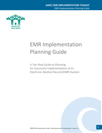
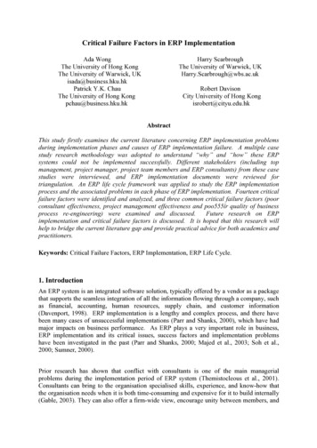
CUBAle de a To,rtueN.pg,-,"-sr',;,t.Por-lde-Pa*f-.- ---!Cap-Ha tier? '- :'-'-:Gona'ivesSaint'--.MarcHnlie de la GonaveHispaniolaX%S-PORPORT-AU-PRINCEgJ6remie. I.-.::MiragoaneJacmelLes Cayest --.DOMINICAN'REPUBLICi In t5S t,e0'30 'ho 0 kmFIG 1.1 Map of Haiti. Petit-Anse is adjacent to thenorthern city of Cap-Haitien [2].Cap-Haitien is capital of the Nord Department, on the Manzanillo Bay, an inlet of theAtlantic Ocean. Cap-Haitien has a large harbor and is an export center for coffee, cocoa, hides,honey, and wood. The estimated population for Cap-Haitien is around 70,000, while for PetitAnse it is around 7,000 [3].Fishing is the primary source of commerce in Petit-Anse. One of the problems in the arearesults from the soil erosion caused by extensive deforestation in Haiti. The water immediatelysurrounding the island has been contaminated and the good fishing stock to shrink and to bepushed further from the shore. This has put additional pressures on the population of Petit-Anse.1.3Client SummaryOur client is the Friends of Petit-Anse (FPA), an organization formed by villagers living inPetit-Anse, and co-sponsored by the non-profit Saint Boniface Foundation of Boston,Massachusetts.Friends of Petite-Anse came into existence in the summer of 2000. The organizationfounded a school for the youth in the village that is designed to offer both fishing vocationaltraining and general education. Friends of Petite-Anse has also established a fishing cooperativethat is run by the villagers.The school affiliated with the organization currently educates approximately 80 studentsages six to eighteen. The students spend half of each day in the classroom on academics, with the7
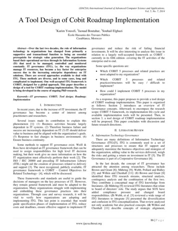
other half spent on vocational fishing education. The FPA has also built a building that will serve,among other purposes, as a health center.FIG 1.2a From left to right, the Petit-Anse church, school, and health center complexI0-VWT . 4, -I-1FIG 1.2b,c (b) Photos of the building exterior and students,(c) Photo of the interior of the health center and variousmembers of the FPA fisherman's cooperative.1.4Our InvolvementThe project was chosen after an IAP 2002 (January term) trip to Haiti through the MITcourse "The Haiti Class" (SP.712). The course was run in both the Fall and Spring terms of the2002-2003 academic year. The Haiti Class was developed through the efforts of Amy Smith ofthe Edgerton Center and the MIT Haitian Alliance. (After the successful work of the first year,the course expanded to include Brazil and India and has been renamed Development Lab, or "DLab"). Course members established partnerships with Haitian NGO's and Peace Corps workers,who assisted us during our work.8
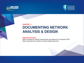
Course members, including the author, traveled to Haiti in January 2002 to assess variousfield sites for potential engineering projects. Through FPA, we were able to visit sites aroundPetit-Anse and develop various project plans. The school and health center were visited, and wewere thus able to assess their electrification needs.The volunteers of the FPA cooperative assisted the team in touring Petit-Anse, and helpedprovide lodging during our stay. During the return trip we anticipate further assistance as well.During the trip, photographs and diagrams were made of the school/health centercomplex. Photographs of the interior, roofs, and general surroundings were taken. These werelater utilized in the design phase of the project. ,- . ;, - ,,m w m- - Om no*mmma am--?- - Om mmWmmmmFIG 1.3a Rear view of the health center.FIG 1.3b Roof of the health center, where the PV panels will be situated9
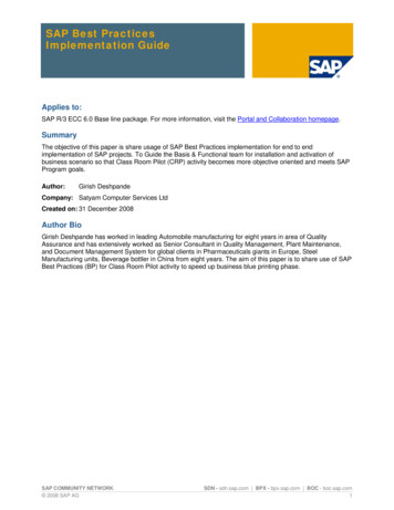
11'---.-11.5'33'38'26.5'1052'9g62'FIG 1.4 Site Layout. Top view is an overhead of the school (on the left) and thehealth center. Bottom view is a profile.2.SYSTEM COMPONENTSIn this chapter we will give a technical overview of the system components. The sectionsare (1) photovoltaic solar panels, (2) end-use applications, (3) charge controller, (4) batteries, and(5) other balance of system (BOS) components. In the subsequent section (Chapter 3, SystemDesign) we will discuss the overall design.2.1Solar PanelsThe system utilizes five 120W panels manufactured by BP (British Petroleum) Solar [I].The panels were off-spec, functional units donated by their chief US production facility inFrederick, Maryland (former headquarters of Solarex International).10
Each panel measures 28.3 lbs and is 57.3" x 28.8" x 1.97" in volume.Each panel iscomposed of 72 multicrystalline silicon cells, wired as 2-series strings with bypass diodes acrosseach 18-cell segment. The cell layer is laminated between sheets of EVA (ethylene vinyl acetate)and high-transmissivity 3mm tempered glass. The multicrystalline panels typically operate at about13%-15% efficiency.FIG 2.1 Front view of the multicrystalline BP 120S panel.See Appendix 6.1 for detailed product specs.With the assistance of Steven Fernandes and his physics students at O'Bryant SecondarySchool, it was found that four of the five panels were on spec for short-circuit current (c) andopen-circuit voltage (Voc), at around 7.7 amps and 21 V, respectively. The fifth panel still needsto be tested.2.2End-Use: Lighting and Refrigeration2.2.1LightingWe decided to mix use of incandescent and fluorescent bulbs, since both were available inCap-Haitien. The fluorescent bulbs offered more efficient lighting, whereas the incandescentbulbs were more easily and cheaply available. The system was designed for six 40W fluorescentbulbs and four 60W incandescent bulbs, which will be purchased on-site in Cap-Haitien.This specific light fixtures to be used will be purchased at MIT. The fluorescent bulbs willbe used exclusively in school lighting and will use standard ceiling fixtures. The lamps used in theexamination area at the health center will be purchased beforehand at MIT.11
11173A,-IF ,,Yil -,1,FIFIG.2.2 Circline fluorescent [4] and incandescent bulbs [5].2.2.2RefrigerationThe refrigeration component is a commercially-available coolbox. We used a"thermoelectric travel cooler/warmer" from Vector Manufacturing. The coolbox uses a 12 V DCinput and draws a continuous 36 watts.FIG 2.3 Thermoelectric Coolbox [6].2.3Charge ControllerA charge controller is necessary to optimize battery power usage for the system. At theminimum, charge controllers prevent the battery bank from overcharging. As of this date a chargecontroller adequate for on-site implementation had not been purchased. We describe below apossible charge controller for small-medium sized PV systems.The charge controller will be rated at between 35 and 40 amps. Prices in this range gofrom 100- 150. This system is at 35.7 amps, so we will look at a 35amp system. One potentialcontroller is the Trace C35 from Xantrex Technology, priced near 110.00 [7]. The unit weightis at 2.7 lb, and unit dimensions are 8.0" x 5.0" x 2.5" (3.0 lb and 12.4" x 7" x 2.5" for shippingweight and dimensions).12
FIG 2.4 Trace C35 from Xantrex Technology [8].2.4BatteriesBatteries store electrical energy, enabling continual delivery of PV power at night or oncloudy days. The batteries used in PV systems are typically deep-cycle (lead-acid) batteries in the100-300 amp-hour range.This system was designed to use two 225 V batteries in parallel. According to ourcontacts in Haiti and our experience in the field, we anticipate purchasing the batteries from themain city area in Cap-Haitien. This will also save time/costs in transporting the batteries.2.5Balance of System (BOS) EquipmentBalance of System (BOS) equipment integrate the structural and electrical components ofthe system with the field site. In addition to the batteries, charge controller, BOS equipmentincludes wiring, component housing, and the PV panel mounts.Further work is needed to determine the final design and construction of the BOScomponents. The wiring will be purchased at MIT and the housing/mounts will be designed andmade on-site in Haiti. The construction of the housing and mounts will depend on additional dataand analysis of the site, and will be undertaken in the field.3.SYSTEM DESIGNIn this section I will describe the overall design of the project. We will describe the clientneeds, project constraints, system sizing, and system integration with the site. The generalintegrated design process was as follows:i. Assessment of client needs (end-use applications, fixed costs) and project constraints(budget, material availability)ii. System Design / Sizing (Determination of load, PV array, battery array)iii. System Integration (Panel roof mounts, lighting/coolbox placement, wiring)Each step of the process was interrelated, and feedback occurred throughout between the client,team members, and the author.13
Below we show a general block diagram of the system and later we will show the wiringdiagram. The block diagram is a typical setup for off-grid, DC, low-wattage systems. The wiringdiagram and sizing tables will be provided later in the section.FIG 3.1 Block Diagram of the System. This is a common model foroff-grid, small to medium DC systems3.1Client RequirementsThe general client requirement was to deliver cheap power for the users of the school andhealth center in Petit-Anse. The system would have to be zero initial cost and low fixed costs. Itshould be easy to maintain and reliable.The school provides after hours vocational and elementary education. Lighting needs forafter hours teaching is approximately 3 hours per day for 6 days a week. The coolbox needsnonstop power, 7 days a week.Client Requirements:Evening LightingContinuous RefrigerationNo Initial CostLow Fixed CostsLow MaintenanceFIG 3.2 Summary of Client RequirementsIn return, the client agreed to offer extensive logistic support during the initial and plannedsite visits.14
3.2Project ConstraintsMinimizing costs and maximizing simplicity was similarly the chief concern throughout thedesign process. Due to these constraints and user feedback, it was decided early to limit the initialproject scope to lighting and medicine refrigeration.Since the site was located off-grid, to minimize cost and inefficiency the system wasdesigned as a DC system. Although an AC system would have allowed for grid connectabilityand more variety of end-use applications, it would have required an DC/AC inverter, increasingthe power inefficiency and component acquisition/ transportation costs.Project Constraints:Low budgetSimpleEasily transportableLimited time frameFIG 3.3 Summary of Project Constraints3.3Load CalculationThe load calculation was done in two iterations. The first iteration was a rough loadestimate to determine the minimum PV amperage needed to complete the project, so thatdonations of PV panels could be sought. The second iteration was a more detailed calculationdone after the panels had been acquired and tested.Given the assumptions of a DC, low-cost system, the initial goal was to determine theloads on the system. The first load element was the refrigeration, and the second element was thebuilding lighting.For the refrigeration component, a product survey suggested that a 50W DC componentcould be purchased. Based on-site experience and site measurements, we assumed lighting byfluorescent bulbs and a minimum of eight bulbs necessary for sufficient lighting of the school andhealth center.For the second iteration, we chose and purchased the refrigeration component andconstructed a more diverse lighting load profile.The optimal refrigeration component was found to be a commercially-available Peltiercoolbox. We purchased a "Thermoelectric travel cooler/warmer" from Vector Manufacturing.The coolbox used a 12V DC input and drew continuous 36 Watts.Several types of lighting were used. We decided on a combination of incandescent andfluorescent, with the option for later use of LED components. Incandescent bulbs were chosen asthe dominant form of lighting for their availability in the region and low-cost. Fluorescent were15
chosen for their higher efficiency and longer life-span.DC LoadCoolboxFluorescentIncandescentUnits W/Unit Total W HrslDay Days/Wk Hrs/Wk ,32014,688FIG 3.4 Load CalculationIn this figure we see the general load profile of the system. The daily and weekly loadsreflect the client requirements discussed in Section 3.1. The wattage values were obtained fromsystem component specs discussed in Section 2.2. The average amp-hours required per day wasobtained by dividing watt-hours/wk by 12V DC by 7 days). This resulted in a total of about 175amp-hrs/day. In the following section, we see how the PV array sizing was done to show that thefive 120W 7.0 peak amp panels obtained were sufficient for the load requirements.3.4PV Array SizingThe initial rough estimate for a minimum 500W system was based on minimal lighting loadestimates for the classroom. Using this index, a 600W panel was requested and obtained from BPSolar. This adequately met initial and final estimates for system amp-hours required.The final estimate for the PV array was based on the load profile described in Section 3.3.This resulted in an approximate total need of 29 amp-hours at max voltage. The optimumamperage of the BP 120S panels was 7.1 amps, sufficient for meeting the overall need of thesystem.Step123456PV SizingTotal Amp-hrs/DayBattery charge/discharge lossAvg sun hours/dayTotal PVAmps requiredPeak Amps / PanelPV Panels RequiredValue174.9145.75.029.17.14.1FIG 3.5 Array Sizing [9].The PV panels required was rounded up to five, which will be more than sufficient giventhe current load and can easily be lowered to four if necessary. The battery discharge loss fromstep 11is obtained by dividing the total amp-hours/day by 1.2. The peak sunlight hours per daywas obtained from the solaration map of the Caribbean region (below). The peak amps data wasobtained from the BP 120S specs (see Appendix 6.1).16
T49 MMA/ 1I,eWrC#rw"tI.- I-COr7c I.AsMA Air Ik&AW C,icr, &aiai,. DOR WA}\' Aquit AAD,UEWS%"tWAf AwrFIG 3.6 Solaration map of Caribbean region [10].3.5Battery Array SizingThe battery array was sized based on a total required value of 174.9 amp-hrs/day needed.Based on client feedback we assigned that the maximum days "no sun/cloudy weather" to twodays (48 hours).By accounting for the 20% deep discharge reserve we calculated the optimum batteryarray size at 437.1 amp-hrs/day. (We assumed that the battery temperature would stay relativelyconstant in the northern Haitian climate, so the optimum temperature multiplier was left at 1.0).Each battery was sized at 225 amp-hrs, which necessitates a two battery array. Since thebatteries have not yet been purchased, the final array size may vary depending on the amp-hrrating of the battery. The data is summarized below in table form.Step12345678Battery SizingTotal amp-hours/dayMax days of little/no sunAmp-hours/Day Required20% Deep Discharge ReserveOptimum temp. multiplierOptimum battery sizeAmp-hours per es in parallel1.9FIG 3.7 Battery Array Sizing [9].3.6Balance of System (BOS) DesignThe design process led to a basic wiring diagram, shown on the following page. In therest of this section, we will describe the other BOS design - panel mounts, wiring, and equipmenthousing.17
3.6.1Panel MountsThe PV panels were designed to be placed flat on the health center roof, so the panelmounts specifications relatively simple. It was not anticipated that the panels will be subject tohigh wind loads, since the panels will be flat and the northern coast of Haiti is not considered ahigh-hurricane risk area.At the moment we are not considering anti-theft elements to the system. The roof isalmost 12 ft off the ground and only accessible via a ladder, stored elsewhere in the health center.During our site visit in Petit-Anse, we also discovered a small ten year old PV installation at arectory, which was similarly placed flat on the roof and lacked any anti-theft mounts (we couldnot determine the origin of the PV system at the time, though we guessed it was built bymissionaries who may have aided in the rectory construction).As we can see in the photos of the health center roof, there are sets of steel stabilizersjutting out in several sections of the roof. In mounting the panels, special care will have to betaken to situate them outside the shadow radius of the stabilizers, to avoid localized shadowing onthe PV cells. (Flat position also helps prevents shadowing of panels on one another, thus allowingfor closer panel spacing.)3.6.2WiringBased on the likely positioning of system components, (See FIG 3. site layout), the totalroundtrip wiring length was approximated at 100 ft. The optimal copper wiring was thendetermined to be at 0 gauge based on a PV array wiring chart from the Redwood Alliance. Giventhat component placement will ultimately be determined on-site, the total wiring length maychange.3.6.3 Equipment HousingThe final design element is the component housing. In particular, the chargecontroller and batteries must be storied securely and in adequate operating conditions.Furthermore the housing can be used to store tools, manuals, and replacement components for thesystem. Currently, the plan is to directly purchase or build the equipment housing on-site in CapHaitien.18
FIG 3.7 Wiring Diagram. From top, clockwise: [I] PV Array.[2] Charge controller, [3] Battery Bank, [4] Lighting and refrigeration loads.19
4.SYSTEM IMPLEMENTATIONIn this section we will outline the implementation plan for the project. We will discussteam development, component acquisition, budget planning, and itinerary planning.Several phases of the project implementation were deferred to a later date (as of now thefinal week of March 2004) due to violence in the Cap-Haitien region during the winter of 20032004. Furthermore, American Airlines, the probable air carrier from the US to Haiti, disallowedcargo carriage to Haiti and the adjoining Dominican Republic during the winter holidays. Thiswould have severely restricted our options for sending the PV panels to Haiti.4.1Funding and Project Costs4.1.1FundingFunding was comprised of funding for (1I)the initial project work in Haiti in January 2003,and (2), project funding for PV system and transportation in Spring of 2004.Major grants for both phases of work was obtained from the Class of'51/'55 Excellencein Education Fund. In year one, 13,000 was received which went towards class developmentand finances for the initial scouting work in January 2003.For the project implementation phase, funding came from a variety of sources. The Classof'51/'55 Excellence in Education Fund donated 7,000, which will be appropriated primarilyamong the D-Lab India and Haiti teams. This funding will cover most of the transportation/ livingcosts for the project implementation team members. Funding to cover PV panel transportationcosts from Virginia to Massachusetts was subsidized using the senior thesis allowance from theMechanical Engineering Department. Funding for various components came from Ed Moriarty ofthe Edgerton Center.4.1.2System CostsCosts estimates were broken down into () system costs and (2) field costs per person. Inthe table below we see an outline of the estimated system costs. We take into account that thePV panels and coolbox were donated or acquired outside of the budget. Since the labor wasvoluntary from MIT students or from FPA it was not included in the initial system cost estimates.20
ComponentPV PanelsPV Panel TransportBatteriesCharge boxMiscellaneousUnits5121116411Cost 0.00 100.00 50.00 110.00 100.00 50.00 5.00 1.00 0.00 100TotalTotal 0.00 100.00 100.00 110.00 100.00 50.00 30.00 4.00 0.00 100.00 594.00FIG 4.1 System Costs4.1.3Field CostsBelow we see the estimated field costs per person. The planned trip is for 9 days,primarily in Cap-Haitien/Petit-Anse. More details on the itinerary in Section 4.4.Cost/Day Days Total Cost/Person 400.00 400.001 90.001 90.002 100.00 50.00 15.007 105.00 15.002 30.007 5.00 35.00 5.009 45.00Total: 805.00ElementBoston - Port-au-Prince (roundtrip)Port-au-Prince- Cap-Haitien (roundtrip)Food & Lodging: Port-au-PrinceFood & Lodging: Cap-HaitienGround Transportation: Port-au-PrinceGround Transportation: Cap-HaitienMiscellaneous Expenses-!-FIG 4.2 Field Costs4.2Component Acquisition and ShippingThus far the PV panels and coolbox have been obtained. We anticipate purchasing thebatteries, lighting, and housing on site in Port-au-Prince and Cap-Haitien. The charge controller,wiring, and tools will be purchased at MIT. We have substantial contacts in Port-au-Prince andCap-Haitien, and do not anticipate major difficulties in purchasing on-site. We also have severalsupplier/machine shop contacts, listed in Appendix 6.3.The primary challenge in transporting the components is in shipping the five PV panels(see Section 2.1 for the weight and dimensions). Shipping via American Airlines to Port-auPrince, though disallowed during the winter holidays, should be feasible in the spring. It isanticipated that panels will then be driven up to Cap-Haitien via rented truck.4.3Team DevelopmentThe original Petit-Anse project team was composed of four members: John Pope, JohanneBlain, Amy Smith, and the author. This team worked on-site in Haiti, scouting the area and21
working on initial project conception. For overall project design, the author was assisted by EdMoriarty, and his colleagues at the O'Bryant School in Cambridge.None of the original team, except the author was scheduled to travel to Petit-Anse duringlAP, so a new Petit-Anse team was formed in the Fall 2003 Development Lab (SP.712).Since the original trip date was rescheduled, the author will work with Amy Smith andJamy Drouillard on forming a third team to travel to Petit-Anse, potentially during the MIT springvacation 2004. This team will likely contain original team members, along with newer D-Labstudents and other colleagues.4.4Travel ItineraryThe current field visit is scheduled to take place during the MIT spring vacation, Saturday,March 20th to Sunday, March 2 8 t h. The itinerary follows a similar schedule as the original trip,minimizing the time spent in Port-au-Prince and maximizing work aP-BostonGeneral TasksTravel, Transporting componentsPurchasing/transporting componentsPurchasing components, SetupInstallationInstallationTestingTestingOn-site closureReturnFIG 4.3 Travel Itinerary.Key: PaP: Port-au-Prince, PA/CH: Petit-Anse/Cap-Haitien.Most of the team members will be MIT students, they will work exclusively during theMIT spring vacation. The author, and any other non-MIT students may extend stay, dependingon funding and team member commitments. Lodging and food will once again be provided byour FPA partners in Cap-Haitien and Petit-Anse.4.5Work Ahead and Concluding RemarksThe primary tasks ahead are obtaining the charge controller, and building/training aproject team. The secondary tasks include writing an installation manual, finalizing the traveldates, detailing the budget, and finalizing logistical matters with our on-site contacts.From a technical standpoint, the project offered a fascinating introduction to (1)engineering work in rural areas of the developing world, and (2) photovoltaic system design.Engineering in developing areas must be cheaper, more durable, and less intrusive, but there isalso great opportunity for finding creative solutions, and a lesser need to adhere to strict legal(e.g. building code) standards. And although the PV system design was simple, it was a useful22
introduction and offers an understanding that can applied to more advanced PV powerengineering
This paper describes the design and implementation of a solar power system for a school and health center in Petit-Anse, Haiti. The end-use applications are lighting via a set of fluorescent and incandescent bulbs, and a coolbox for medical refrigeration at the health center. The power is derived from five