Transcription
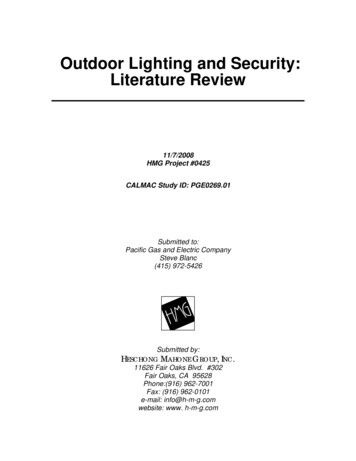
CrestfieldInstallation ManualModel: 54207 Fresh White54208 Noble Bronze54209 Brushed NickelFan weight 2 lbs: 22.7 lbs (10.3 kg) 2018 Hunter Fan Co.PG3613 r032818
Congratulations on purchasing your new Hunter ceiling fan!The ceiling fan you purchased will provide comfort and performance in your home or office for many years. Thisinstruction manual contains complete instructions for installing and operating your fan. We are proud of our work andappreciate the opportunity to supply you with the best ceiling fan available anywhere in the world.We are here to help!This Instruction Manual is designed to make installation as simple as possible. While working through this InstructionManual, keep your smartphone or tablet nearby. We have added video links to help you through the more technicalsections. If you are unfamiliar or uncomfortable with wiring, contact a qualified electrician. We also provide telephonesupport at 1.888.830.1326 or visit us at HunterFan.com.READ and SAVE These Instructions18861886WARNINGWarning.1 - To reduce the risk of fire, electrical shock, or personal injury, mount fan directly from building structure and/or an outlet box marked acceptable for fan support of 70 lbs (31.8 kg) and use themounting screws provided with the outlet box.w.2 - To avoid possible electrical shock, before installing or servicing your fan, disconnect the power by turning off the circuit breakers to the outlet box and associated wall switch location. If youcannot lock the circuit breakers in the off position, securely fasten a prominent warning device, such as a tag, to the service panel.w.3 – To reduce the risk of electric shock, this fan must be installed with an isolating wall control/switch.w.4 - To reduce the risk of personal injury, do not bend the blade brackets when installing the blade brackets, balancing the blades, or cleaning the fan. Do not insert foreign objects in betweenrotating fan blades.Cautionc.1 - All wiring must be in accordance with national and local electrical codes ANSI/NFPA 70. If you are unfamiliar with wiring, use a qualified electrician.c.2 - Use only Hunter replacement parts.This equipment has been tested and found to comply with the limits for a Class B digital device, pursuant to part 15 of the FCC Rules. These limits are designed to provide reasonable protectionagainst harmful interference in a residential installation. This equipment generates, uses and can radiate radio frequency energy and if not installed and used in accordance with the instructionsmay cause harmful interference to radio communications.However, there is no guarantee that interference will not occur in a particular installation. If this equipment does cause harmful interference to radio or television reception, which can bedetermined by turning the equipment off and on, the user is encouraged to try to correct the interference by one or more of the following measures: Reorient or relocate the receiving antenna. Increase the separation between the equipment and receiver. Connect the equipment into an outlet on a circuit different from that to which the receiver is connected. Consult the dealer or an experienced radio/TV technician for help.Caution: modifications not approved by the party responsible for compliance could void user’s authority to operate the equipment.This device complies with Part 15 of the FCC Rules. Operation is subject to the following two conditions: (1) This device may not cause harmful interference, and (2) this device must accept anyinterference received, including interference that may cause undesired operation.This product conforms to UL Standard 507.Certified to CSA Standard C22.2 No. 113Here are the tools you’ll need to complete your installation:OPTIONALIf mounting to a support structure, you will also need these tools.LadderScrewdriverDrillPliers1Wire Strippers9/64” Drill Bit
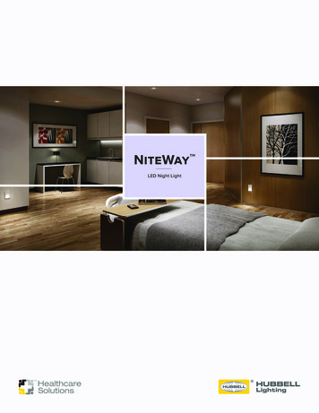
1886Here is what comes in your box:We recommend that you pull everything out of the box and lay it out. We havegrouped the drawn components below with the hardware you’ll need for thoseparts. The screws below are drawn to scale to make it easier to identify whatpiece of hardware is needed to install each component.Hunter Pro Tip:Do not discard the hardware bags or mix parts fromdifferent bags. Make note of the symbol printed oneach hardware bag. The symbols can be used toidentify the appropriate hardware for each step.Ceiling Bracketx2Wood ScrewbagWire NutWasherx2x4LockingScrewx2For installing the hanger bracket and wiring the fanMotor HousingScrewbagx4For installing the housingMotorMotor HousingBladesx5Upper Switch Housingx10For installing the bladesbagBlade Armx5Blade Arm ScrewbagLower Switch Housingx3Spare PartsFor your convenience,you may receive extra fasteners.bagPullchainsLight Kit ScrewGlassx3x3Switch HousingScrewBulbNote:x3Fan style may vary.For installing the light fixtureFind a part that is missing or damaged?Don’t take it back to the store. Let us make it right. Visit us at HunterFan.com or call us at 1.888.830.1326.M0211-01 r0402182
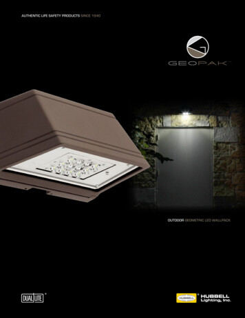
1886Choosing the Right Installation LocationYou probably bought this fan with a location in mind. Let’s check below to make sure it is a good fit.Check the room dimensions:Check the outlet box:30 inchesfrom blade tip tonearest wall orobstructionYou must be able tosecure the fan to buildingstructure or fan-ratedoutlet box.7 feetfrom bottom edgeof blade to thefloorInstalling the Ceiling BracketYou have two options for installation. Pick which one works best for your location.tare still atached.Do this first!m p e rserowPnrTua llfo ur buOFFMakesureWasherOption 2:Wood ScrewsOption 1:Machine ScrewsUse wood screws (included)when securing to supportstructure with approvedelectrical outlet box. Drill 9/64”pilot holes in support structureto aid in securing ceiling bracketwith hardware found in thehardware bag.Use machine screws (provided with outlet box) whensecuring to existing ceilingfan-rated outlet box. Makesure it is securely installedand is acceptable for fansupport of 31.8 kg (70 lbs)or less.x2bagx2Wood ScrewHunter Pro Tip:The machine screws are the onesthat came with your outlet box.3Ceiling BracketHanging FanWiringMotor HousingBladesLight
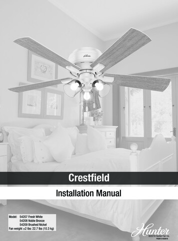
1886STEPSTEPHanging the Fan12x2bagLockingScrewWhile holding the wires out of the way, lift themotor assembly and place the square hangerinto the opening in the ceiling bracket. Be surethe ground wire attached to the hanger facesout of the large opening in the ceiling bracket.Once the motor is in the ceiling bracket,use the two locking screws found in thehardware bag to secure the motorto the ceiling bracket.Wiring the FanWe know wiring is hard. Let’s make it easier.Follow these steps to get your fan wired quickly and safely. Follow the route below that best matches your wall switch setup. If you are unfamiliar with wiring oruncomfortable doing it yourself, please contact a qualified electrician.Hunter Pro Tip:Here is how to connect the wires:Push the bare metal ends of the wires together and slide a wirenut over them. Then, twist the wire nut clockwise until tight.Give it a gentle pull to make sure none of the wires are loose.Have a single switch?Follow these steps:GroundedConnect the white(grounded) wire fromthe ceiling to the whitewire from the fan.WhiteUngroundedwlloYeen/GreConnect the threegrounding wires (green,green/yellow stripe, orbare copper) coming fromthe ceiling and nnect the black wire(ungrounded) from theceiling to the black and theblue wires from the fan.Groundingx4bagWire NutHunter Pro Tip:Have extra wiring?Turn the wires upward and push them carefully back throughthe hanger bracket into the outlet box. Make sure that thewires are still attached to the wire nuts.Have dual switches?Follow these steps:GroundedConnect the white(grounded) wire fromthe ceiling to the whitewire from the fan.WhiteStrwlloYeen/GreCeiling BracketStripeBlueConnect the threegrounding wires (green,green/yellow stripe, orbare copper) coming fromthe ceiling and lloYeen/GrewConnect the secondungrounded (light)wire from theceiling to the bluewire from the fan.Connect the black wire(ungrounded) from theceiling to the blackwire from the fan.GroundingHanging Fanx4bagWiringMotor HousingBladesWire NutLight4
18861STEPSTEPInstalling the Motor HousingNotch2x4bagMotor HousingScrewIndentationRaise the motor housing up over the motor and ceilingbracket. Turn the motor housing so the screw holes alignand the indentation in the housing locks into place withthe notch in the ceiling bracket. The motor housing isnot secured until the next step is complete. Do notleave unattended.With a Phillips head screwdriver, installthe four motor housing screws found inthehardware bag. Tighten all fourscrews securely.Installing the Blades:Align the three blade holes with the threeblade iron posts. Squeeze the blade andthe blade iron post together.Repeat x5The flared tops of the blade iron posts will be fullyvisible above the blade when properly assembled.Lightly attach the blade arms to the motor withthe blade arm screws, then securely tightenafter both screws are attached.x10Blade ArmBladeScrewArm ScrewbagRepeat x5Note:Fan style may vary.5Ceiling BracketHanging FanWiringMotor HousingBladesLight
18861STEPSTEPSTEPAssembling the Light232 of 3bagScrew light kit screws from thehardware bag halfway intothe motor housing. It does notmatter which two screw holesyou choose.WARNINGFAN FALL HAZARDMake sure all three screws are tight to securethe upper switch housing to the mounting plate.STEPSTEPLight Kit ScrewInsert a third screw, found in thehardware bag, into place andthen tighten all three screws.Feed the wire plug through the centerhole of the upper switch housing,then wrap keyhole slots around thescrews and twist counterclockwise.52 of 3Light Kit Screw4bagConnect the plugs from the upper andlower switch housings. Make sure to lineup the colored markings on the connectors.STEPbag1 of 3Light Kit Screw1 of 36Light Kit ScrewbagInstall the last light kit screw. Tighten allthree screws securely.Partially install two of the light kit screwsfound in thehardware bag. Align thenotches in the sides of the lower switchhousing with the screws on the upperswitch housing. Twist the lower switchhousing clockwise to lock into place.WARNINGFAN FALL HAZARDMake sure all three screws are tight to secure thelower switch housing to the upper switch housingInstalling the Bulbs and GlassInstall a bulb into eachof the sockets. Whennecessary, replace withbulbs of same wattage.Repeat x3rwePonrTuTo install the shade, first loosenthe thumb screws. Raise theshade to the light fixture. Tightenall thumbscrews securely.ONWARNINGRepeat x3Hunter Pro Tip:Want to install your fan without a light kit?Go to www.HunterFan.com/FAQs and click “How do I install myfan without the light kit?”Ceiling BracketHanging FanGLASS FALL HAZARDTo prevent SERIOUS INJURY or DEATH, makesure that glass is properly secured.Note:Fan style may vary.WiringMotor HousingBladesLight6
1886Installing the Pull ChainsFeed the pull chains from the fan switchand the light switch down through theholes in the upper switch housing asshown. Attach the pull chain pendantsto the light and fan pull chains.The fan pull chain controlsthe speed: from high to off.The light pull chain controlsthe light fixture: on and off.Repeat x2Reversing the FanCeiling fans work in two directions: downdraft (counterclockwise rotation) and updraft (clockwiserotation). To change the direction of air flow, turn the fan off and let it come to a complete stop.The reversing switch is located inside the light fixture cage. It can only be accessed when thecage is removed. Slide the reversing switch to the opposite position. Restart the fan.ReverseSwitchUpdraft (clockwise rotation)creates a more indirect airflow.Updraft airflow is great formoving warm air downward.Downdraft (counterclockwiserotation) creates a direct breezeand maximum cooling effect.7
1886TroubleshootingFan Doesn’t WorkExcessive Wobbling Make sure power switch is on. Pull the pull chain to make sure it is on. Push the motor reversing switch firmly left or right toensure that it is engaged. Check the circuit breaker to ensure the power isturned on. Make sure the blades spin freely. Turn off power from the circuit breaker, then loosenthe canopy and check all the connections accordingto the wiring diagram. Check the plug connection in the switch housing. Make sure the blades are properly installed on theblade iron posts. Turn the power off, support the fan carefully, andcheck that the hanger ball is properly seated. Use the provided balancing kit and instructions tobalance the fan.Noisy Operation Make sure the blades are properly installed. Check to see if any of the blades are cracked. If so,replace all of the blades.Hunter Pro Tip:Cleaning the FanUse soft brushes or cloths to prevent scratching.Cleaning products may damage the finishes.Limited Lifetime WarrantyHunter Fan Company grants this limited warranty to the original purchaser of this Hunterceiling fan. This document can be found at www.HunterFan.com.Thank you for choosing Hunter!How Can Warranty Service Be Obtained?Proof of purchase is required when requesting warranty service. The originalpurchaser must present a sales receipt or other document that establishes proof ofpurchase. Hunter, at its sole discretion, may accept a gift receipt. To obtain service,contact Hunter Fan Company online or by 30-1326Please do not ship your fan or any fan parts to Hunter. Delivery will be refused.What Does This Warranty Cover?Motor — Limited Lifetime WarrantyIf any part of your ceiling fan motor fails during your ownership of the fan due to adefect in material or workmanship, as determined solely by Hunter, Hunter will provideyou with a replacement fan free of charge.* The foregoing limited warranty applies onlyto the motor itself and does not apply to electronic controls – such as remote controltransmitters, remote control receivers, or capacitors – used in conjunction with themotor. Such electronic control items are included in the one-year limited warranty below.Other — One-Year Limited WarrantyExcept as otherwise indicated throughout this warranty, if any part of your Hunter ceilingfan fails at any time within one year of the date of purchase due to a defect in materialor workmanship, as determined solely by Hunter, Hunter will provide a replacement partfree of charge.*Light Kits — Warranty May VaryLight kits are included in the one-year limited warranty. However, you may qualify foradditional warranty coverage if your fan includes one of the following: LED Light Kits — Three-Year Limited WarrantyIf your LED light kit module (not including glass components) or LED bulbfails at any time within three years of the date of purchase due to a defectin material or workmanship, as determined solely by Hunter, Hunter willprovide a replacement part free of charge.* ENERGY STAR Rated Light Kits — Three-Year Limited WarrantyIf your ENERGY STAR rated light kit (not including glass components) failsat any time within three years of the date of purchase due to a defect inmaterial or workmanship, as determined solely by Hunter, Hunter will providea replacement light kit free of charge.** If no replacement product/part can be provided for your fan, we will provide a comparable orsuperior replacement product/part at the sole discretion of Hunter.What Does This Warranty NOT Cover?Labor Excluded. This warranty does not cover any costs or fees associated with the labor(including electrician’s fees) required to install, remove, or replace a fan or any fan parts.There is no warranty for light bulbs (except where otherwise noted); remote controlbatteries; fans purchased or installed outside the United States; fans owned bysomeone other than the original purchaser; fans for which proof of purchase has notbeen established; fans purchased from an unauthorized dealer; ordinary wear and tear;minor cosmetic blemishes; refurbished fans; and fans that are damaged due to anyof the following: improper installation, misuse, abuse, improper care, failure to followHunter instructions, accidental damage caused by the fan owner or related parties,modifications to the fan, improper or incorrectly performed maintenance or repair,improper voltage supply or power surge, use of improper parts or accessories, failure toprovide maintenance to the fan, or acts of God (e.g. flood).ORIGINAL PURCHASER’S SOLE AND EXCLUSIVE REMEDY FOR A CLAIM OF ANY KINDWITH RESPECT TO THIS PRODUCT SHALL BE THE REMEDIES SET FORTH HEREIN.HUNTER FAN COMPANY IS NOT RESPONSIBLE FOR CONSEQUENTIAL OR INCIDENTALDAMAGES, DUE TO PRODUCT FAILURE, WHETHER ARISING OUT OF BREACH OFWARRANTY, BREACH OF CONTRACT, OR OTHERWISE. Some States do not allow theexclusion or limitation of incidental or consequential damages, so the above limitation orexclusion may not apply to you.ANY IMPLIED WARRANTIES OF MERCHANTABILITY OR FITNESS FOR A PARTICULARPURPOSE APPLICABLE TO THIS PRODUCT ARE LIMITED IN DURATION TO THE PERIOD OFCOVERAGE OF THE APPLICABLE LIMITED WARRANTIES SET FORTH ABOVE. Some Statesdo not allow limitations on how long an implied warranty lasts, so the above limitationmay not apply to you.How Does State Law Affect Warranty Coverage?This warranty gives you specific legal rights. You may also have other rights which varyfrom state to state.8
cannot lock the circuit breakers in the off position, securely fasten a prominent warning device, such as a tag, to the service panel. w.3 – To reduce the risk of electric shock, this fan must be installe