Transcription
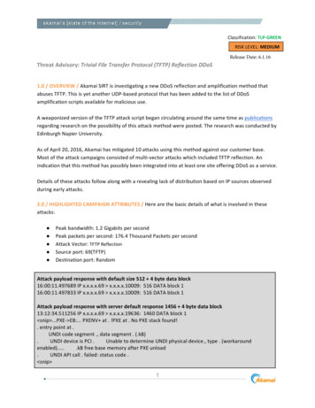
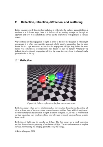
2Reflection, refraction, diffraction, and scatteringIn this chapter we will describe how radiation is reflected off a surface, transmitted into amedium at a different angle, how it is influenced by passing an edge or through anaperture, and how it is scattered and spread out by interactions with particles at variousscales.We will focus on the propagation of light. In order to describe the direction in which lightpropagates, it is often convenient to represent a light wave by rays rather than by wavefronts. In fact, rays were used to describe the propagation of light long before its wavenature was established. Geometrically, the duality is easy to handle: Whenever weindicate the direction of propagation of light by a ray, the wave front is always locallyperpendicular to the ray.2.1 ReflectionFigure 2-1. Spheres reflected in the floor and in each other.Reflection occurs when a wave hits the interface between two dissimilar media, so that allof or at least part of the wave front returns into the medium from which it originated.Common examples are reflection of light, as shown in figure 2-1, as well as reflection ofsurface waves that may be observed in a pool of water, or sound waves reflected as echofrom a wall.Reflection of light may be specular or diffuse. The first occurs on a blank mirroringsurface that retains the geometry of the beams of light. The second occurs on a roughersurface, not retaining the imaging geometry, only the energy. Fritz Albregtsen 2008
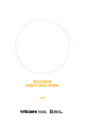
2-2Reflection, refraction, diffraction, and scattering2.1.1 ReflectanceReflectance is the ratio of reflected power to incident power, generally expressed indecibels or percent. Most real objects have some mixture of diffuse and specularqualities, and surface reflectance is therefore often divided into diffuse and specularreflectance. In climatology, reflectivity is called albedo.2.1.2 Diffuse reflectionWhen light strikes a rough or granular surface, it bounces off in all directions due to themicroscopic irregularities of the interface, as illustrated in figure 2-2. Thus, an image isnot formed. This is called diffuse reflection. The exact form of the reflection depends onthe structure of the surface.Figure 2-2. Diffuse reflection from a rough surface.A common model for diffuse reflection is Lambertian reflectance, in which the light isreflected in accordance with Lambert's cosine law, see figure 2-3.Lambert's cosine law says that the total radiant power observed from a "Lambertian"surface is directly proportional to the cosine of the angle θ between the observer's line ofsight and the surface normal. The law is also known as the cosine emission law orLambert's emission law (Johann Heinrich Lambert, Photometria, 1760).When an area element is radiating as a result of being illuminated by an external source,the irradiance (energy/time/area) landing on that area element will be proportional to thecosine of the angle between the illuminating source and the normal. A Lambertianreflector will then reflect this light according to the same cosine law as a Lambertianemitter.This means that although the radiance of the surface under diffuse reflection depends onthe angle from the normal to the illuminating source, it will not depend on the angle fromthe normal to the observer. Fritz Albregtsen 2008
Imaging2-3An important consequence of Lambert's cosine law is that when an area element isviewed from any angle, it has the same radiance. Although the emitted power from anarea element is reduced by the cosine of the emission angle, the observed size of the areaelement is also reduced by that same amount, so that while the area element appearssmaller, its radiance is the same.Figure 2-3. Emission rate (photons/s) in a normal and off-normal direction. The numberof photons/sec directed into any wedge is proportional to the area of the wedge.2.1.3 Specular (mirror-like) reflectionWe describe the directions of the incident ray hitting an optical surface and the ray beingreflected from the surface in terms of the angle they make with the normal(perpendicular) to the surface at the point of incidence, as shown in figure 2-4. Inspecular reflection, the angle of incidence θi equals the angle of reflection θr.Figure 2-4. Reflection from a mirror.A mirror is the most common example of specular light reflection. It usually consists of aglass sheet in front of a metallic coating where the reflection actually occurs. Reflectionalso occurs from the surface of transparent media, such as water or glass. Fritz Albregtsen 2008
2-4Reflection, refraction, diffraction, and scatteringIn fact, reflection of light may occur whenever light travels from a medium of a givenrefractive index into a medium with a different refractive index. In the most general case,a certain fraction of the light is reflected from the interface, and the remainder is refractedas it passes into the transparent medium.When light reflects off a material denser than the external medium, it undergoes a 180 phase reversal. In contrast, a less dense, lower refractive index material will reflect lightin phase. This is an important principle in the field of thin-film optics.Specular reflection at a curved surface forms an image which may be magnified ordemagnified. We will shortly return to the subject of curved mirrors and geometric optics.2.1.4 Perfect mirrorsA perfect mirror is a theoretical mirror that reflects light (and electromagnetic radiationin general) perfectly, and doesn't transmit it. Domestic mirrors are not perfect mirrors asthey absorb a significant portion of the light which falls on them.Dielectric mirrors are glass or other substrates on which one or more layers of dielectricmaterial are deposited, to form an optical coating. A very complex dielectric mirror canreflect up to 99.999% of the light incident upon it, for a narrow range of wavelengths andangles. A simpler mirror may reflect 99.9% of the light, but may cover a broader range ofwavelengths.2.1.5 Image formation by a plane mirrorAs illustrated by figure 2-5, a plane mirror will form a virtual image point located exactlyopposite the real image point, and as far behind the mirror as the object point is from thefront of the mirror.Figure 2-5. The location of the virtual image formed by a plane mirror.Evidently, a “full size mirror” for your wardrobe doesn’t have to more than half theheight of your body, no matter where on your body your eyes are placed, and no matterhow far away from the mirror you are standing. The image of an extended object seen ina plane mirror is exactly the same size as the object, but it is perceived to be located at anegative image distance behind the mirror, equal to the positive object distance from themirror. And since the object and image sizes are the same, the lateral magnification isunity. Fritz Albregtsen 2008
Imaging2-52.1.6 Retro reflectionRetro reflectors are used both in a purely specular and a diffused mode. A simple retroreflector can be made by placing three ordinary mirrors mutually perpendicular to oneanother (a corner reflector). The image produced is the inverse of one produced by asingle mirror. The principle is illustrated for two mirrors in figure 2-6. Applications alsoinclude simple radar reflectors for ships, and the Lunar Laser Range program based onfour retro reflectors placed at the Apollo 11, 14, and 15 sites and the Lunakhod 2 rover.In such applications, it is imperative that the corner angle is exactly 90 . A deviation byan angle δ will cause the returned beam to deviate by 2δ from the incoming beam.Figure 2-6. The principle of a retro reflector.Surfaces may also be retroreflective. The structure of these surfaces is such that light isreturned in the direction from which it came.A surface can be made partially retroreflective by depositing a layer of tiny refractivespheres on it or by creating small pyramid like structures (cube corner reflection). In bothcases internal reflection causes the light to be reflected back to where it originated. Thisis used to make traffic signs and automobile license plates reflect light mostly back in thedirection from which it came. In this application a completely perfect retro reflection isnot desired, since the light would then be directed back into the headlights of anoncoming car rather than to the driver's eyes.The description of retro reflectors may illustrate an important property of all imagesformed by reflecting or refracting surfaces: An image formed by one surface can serve asthe object for a second imaging surface. In the case of two orthogonal mirrors as shownin figure 2-7, mirror M1 forms a virtual image P1’ of an object point P, and mirror M2forms another virtual image P2’. Image P1’ serves as an object for mirror M2, forming avirtual image P3’. Likewise, image P2’ serves as an object for mirror M1, forming thesame virtual image P3’. Fritz Albregtsen 2008
2-6Reflection, refraction, diffraction, and scatteringP2’P3’PP2’M1M2Figure 2-7. Virtual images P1’ and P2’ are formed by a single reflection of the object P inmirrors M1 and M2, respectively. The virtual image P3’ is formed by a reflection of thevirtual image P1’ in mirror M2 or image P2’ in mirror M1.This principle will be used extensively when locating the final image formed by severalsuccessive reflecting surfaces in a mirror-based telescope, or several refracting surfacesin a microscope or a refracting telescope.2.1.7 Sign rules for image formationIn the case of an image formed by a few plane mirrors, the geometry is quite simple, andwe do not have to worry about the sign of object and image distances. However, we wantto state some general sign rules that will be applicable to all imaging situations that wewill encounter later, when both real and virtual images are formed in front of or behindcurved surfaces: The object distance: When the object is on the same side of the reflecting orrefracting surface as the incoming light, the object distance s is positive;otherwise, it is negative. The image distance: When the image is on the same side of the reflecting orrefracting surface as the outgoing light, the image distance s’ is positive;otherwise, it is negative. Radius of curvature: When the centre of curvature C is on the same side as theoutgoing light, the radius of curvature is positive; otherwise, it is negative. Fritz Albregtsen 2008
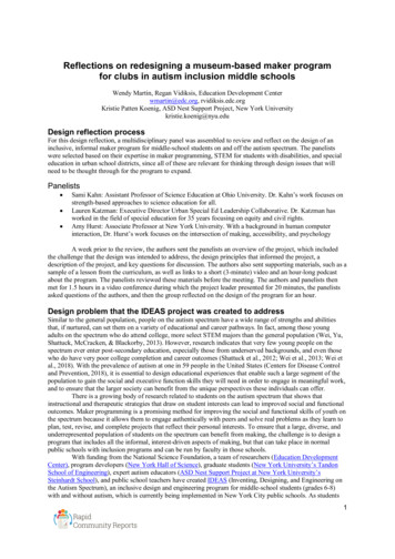
Imaging2-72.1.8 Image formation by curved mirrors2.1.8.1 Spherical mirrorsRφαPCθθhβδP’s’sFigure 2-8.Finding the image point formed by a concave mirror.Figure 2-8 shows a spherical mirror with radius of curvature R. The concave side isfacing the incident light originating from an object point P on the optical axis. A ray fromP at an angle α to the axis is reflected by the mirror. The angle of incidence and reflectionare both θ, and the reflected ray crosses the optical axis at an angle β. In fact, all raysfrom P will intersect the axis at the same point P’, provided that the angle α is small.We have the following relations: φ α θ and β φ θ, which implies that α β 2 φ.The expressions for the tangents of α, β, and φ are simply tg(α) h/(s-δ), tg(β) h/(s’-δ),tg(φ) h/(R-δ). If the angle α is small, so are β and φ. If α is so small that the ray isalmost parallel to the optical axis (the paraxial approximation), the tangent of an angle isequal to the angle itself (given in radians), and δ may be neglected compared to s, s’, andR. So for small angles we have the following approximations: α h/s, β h/s’, φ h/R.Substituting this into φ α θ we get the general object-image relation for a sphericalmirror:1 1 2 s s' RIf the radius of curvature becomes infinite (R ), the mirror becomes plane, and therelation above reduces to s -s’ for a plane reflecting surface.If the object is very far from the mirror (s ), the incoming rays are parallel, and theimage will be formed at a distance s’ R/2 from the mirror. This is the focal length, f. Fritz Albregtsen 2008
2-8Reflection, refraction, diffraction, and scatteringA simple sketch may illustrate how the size y’ and position s’ of the real image of anextended object is determined, once the size y of the object , the distance s from thespherical mirror to the object and the radius R of curvature of the mirror is known, seefigure 2-9.sRyPCs’P’y’Figure 2-9. Determining the position, orientation and size of an image.We see that y/s - y’/s’. The negative sign indicates that the image is inverted relative tothe object. The magnification is m y’/y - s’/s. The size of the image is y’ ys’/s.Substituting s’ from the general object-image relation, we get a more useful expression: y’ yf /(s-f), as the object distance s and the focal length f are often readily available.When the object is far from the mirror, the image of the object is smaller than the object,inverted, and real. If the object for all practical purposes is infinitely far away, the imageis formed in the focal plane. As the object is moved closer to the mirror, the image movesfarther from the mirror and increases in size. When the object is in the focal plane, theimage is at infinity. If the object is inside the focal point, the image becomes larger thanthe object, erect, and virtual.For a convex spherical mirror, R is negative. A virtual image is formed behind the mirrorat a negative image distance. But using the sign rules, the same object-image relation isvalid, and the expressions for the magnification and the size of the image are the same.However, if the incoming rays are parallel to the optical axis, the rays will not convergethrough a focal point. They will diverge as if they had come from a virtual focal point atnegative focal length f R/2 behind the mirror. In summary, the basic relationships forimage formation by a spherical mirror are valid for both concave and convex mirrors,provided that the sign rules are used consistently. Fritz Albregtsen 2008
Imaging2-92.1.8.2 Optical aberrations caused by curved mirrors2.1.8.2.1 Spherical aberrationA simple mirror with a spherical surface suffers from the optical imperfection calledspherical aberration: Light striking nearer the periphery focuses closer to the mirror,while light striking near the center focuses farther away. While spherical mirrors are themost convenient to grind and polish, spherical aberration can be eliminated by grindingand polishing the surface to a paraboloid of revolution. Then parallel rays striking allparts of the mirror are reflected to the same focus.2.1.8.2.2 ComaThe principal disadvantage of a parabolic mirror is that it produces good images overonly a relatively small field of view, that is, for light that strikes the mirror very nearlyparallel to the optical axis. In a photograph of a field of stars, the star images near thecenter of the picture will appear as sharp, round dots, whereas those near the corners,which are formed by light coming in at an angle to the optical axis, are distorted into tiny“tear drops” or “commas” pointing towards the center of the photograph. The shape ofthese images accounts for the name “coma” given to this type of aberration that distortsimages formed by light that strikes the mirror off-axis.2.1.8.2.3 AstigmatismAstigmatism occurs when rays of light in different planes do not focus at the samedistance from the mirror. Such aberrations may be caused by mechanical distortions oflarge mirrors.2.1.8.2.4 Curvature of fieldThis is an aberration in which the image is sharp, but different parts of it are formed atdifferent distances from the mirror, so that the whole image cannot be captured by a flatdetector.2.1.8.2.5 DistortionThis is an aberration in which the image may be sharp, but its shape is distorted, e.g. ifstraight lines in the object plane are imaged as curved lines. Distortion may vary withinthe field of view, being most noticeable near the edges of the field of view.2.1.8.2.6 VignettingThis is an aberration that causes a darkening of the image towards the corners of the fieldof view. Fritz Albregtsen 2008
2-10Reflection, refraction, diffraction, and scattering2.1.8.3 Reflecting telescopesA telescope (from the Greek tele 'far' and skopein 'to look or see'; teleskopos 'farseeing') is an instrument designed for the observation of remote objects. There are threemain types of optical astronomical telescopes: The refracting (dioptric) telescope which uses an arrangement of lenses. The reflecting (catoptric) telescope which uses an arrangement of mirrors. The catadioptric telescope which uses a combination of mirrors and lenses.The Italian monk Niccolo Zucchi is credited with making the first reflector in 1616, buthe was unable to shape the concave mirror accurately and he lacked of means of viewingthe image without blocking the mirror, so he gave up the idea. The first practical reflectordesign is due to James Gregory. In Optica Promota (1663) he described a reflector usingtwo concave mirrors. A working example was not built until 10 years later by RobertHooke. Sir Isaac Newton is often credited with constructing the first "practical" reflectingtelescope after his own design in 1668. However, because of the difficulty of preciselyproducing the reflecting surface and maintaining a high and even reflectivity, thereflecting telescope did not become an important astronomical tool until a century later.Telescopes increase the apparent angular size of distant objects, as well as their apparentbrightness. If the telescope is used for direct viewing by the human eye, an eyepiece isused to view the image. And most, if not all eyepiece designs use an arrangement oflenses. However, in most professional applications the image is not viewed by the humaneye, but is captured by photographic film or digital sensors, without the use of aneyepiece. In this configuration, telescopes are used as pure reflectors.We will return to the effects of an eyepiece in the sections on refraction.In a prime focus design in large observatory telescopes, the observer or image detectorsits inside the telescope, at the focal point of the reflected light. In the past this would bethe astronomer himself, but nowadays CCD cameras are used. Radio telescopes alsooften have a prime focus design.2.1.8.4 Telescope mountingsThe telescope tube must be mounted so that it can point to any direction in the sky. Thisis achieved by using two orthogonal axes of motion. The simplest is an altitude-azimuth mount, where one axis points towards thezenith, and the instrument is pointed at a given altitude angle above the horizon,measured along a vertical circle, and a given azimuthal angle, measured eastwardfrom the north point. Following a celestial object over time requires repeatedrecalculation of altitude and azimuth if this mount is used. In the equatorial mount, one axis is parallel to the earth’s axis. This allows thetelescope to be pointed directly in right ascension and declination, the coordinatesin which astronomical positions are generally given. In addition, a simpleclockwork about a single axis can compensate for the earth’s rotation whenobserving celestial objects. Fritz Albregtsen 2008
Imaging2-112.1.8.5 Optical reflecting telescope designs The Newtonian usually has a paraboloid primary mirror but for small apertures, aspherical primary mirror is sufficient for high visual resolution. A flat diagonalsecondary mirror mounted on a “spider” reflects the light to a focal plane at theside of the top of the telescope tube. Thus, the observer does not block the lightentering the telescope tube. However, the observer may experience someawkward viewing positions.Figure 2-10. A “classic” Cassegrain telescope design. The “classic” Cassegrain has a parabolic primary mirror, and a convexhyperbolic secondary mirror that reflects the light back, either through a hole inthe primary, or reflected out to the side of the tube by a third, flat mirror, mounteddiagonally just in front of the primary (the Nasmyth-Cassegrain). Folding theoptics makes this a compact design. On smaller telescopes, and camera lenses, thesecondary is often mounted on a clear, optically flat, glass plate that closes thetelescope tube. This eliminates the diffraction effects caused by the secondarysupports in the Newtonian. It also protects the mirrors from dust.The Ritchey-Chrétien is a specialized Cassegrain reflector which has twohyperbolic mirrors (instead of a parabolic primary). It is free of coma andspherical aberration at a flat focal plane, making it well suited for wide field andphotographic observations. Almost every professional reflector telescope in theworld is of the Ritchey-Chrétien design.The Dall-Kirkham Cassegrain design uses a concave elliptical primary mirrorand a convex spherical secondary. While this system is easier to grind than aclassic Cassegrain or Ritchey-Chretien system, it does not correct for off-axiscoma and field curvature so the image degrades quickly off-axis. Because this isless noticeable at longer focal ratios, Dall-Kirkhams are seldom faster than f/15.The Schiefspiegler uses tilted mirrors to avoid the secondary mirror casting ashadow on the primary. However, while eliminating diffraction patterns this leadsto several other aberrations that must be corrected.The Maksutov telescope uses a full aperture corrector lens, a spherical primary,and a spherical secondary which is an integral part of the corrector lens.The Gregorian has a concave, not convex, secondary mirror and in this wayachieves an upright image, useful for terrestrial observations.A Schmidt camera is an astronomical camera designed to provide wide fields ofview with limited aberrations. It has a spherical primary mirror, and an asphericalcorrecting lens, located at the center of curvature of the primary mirror. The filmor other detector is placed inside the camera, at the prime focus. The Schmidtcamera is typically used as a survey instrument, for research programs in which alarge amount of sky must be covered. There are several variations to the design: Fritz Albregtsen 2008
2-12Reflection, refraction, diffraction, and scatteringo Schmidt-Väisälä: a doubly-convex lens slightly in front of the film holder.o Baker-Schmidt: a convex secondary mirror, which reflected light backtoward the primary. The photographic plate was then installed near theprimary, facing the sky.o Baker-Nunn: replaced the Baker-Schmidt camera's corrector plate with asmall triplet corrector lens closer to the focus of the camera. A 20 inchBaker-Nunn camera installed near Oslo was used to track artificialsatellites from the late 1950s.o Mersenne-Schmidt :consists of a concave paraboloidal primary, a convexspherical secondary, and a concave spherical tertiary mirror.o Schmidt-Newtonian: The addition of a flat secondary mirror at 45 to theoptical axis of the Schmidt design creates a Schmidt-Newtonian telescope.o Schmidt-Cassegrain: The addition of a convex secondary mirror to theSchmidt design directing light through a hole in the primary mirror createsa Schmidt-Cassegrain telescope. The last two designs are popular becausethey are compact and use simple spherical optics. The Nasmyth design is similar to the Cassegrain except no hole is drilled in theprimary mirror; instead, a third mirror reflects the light to the side and out of thetelescope tube, as shown in figure 2-11.Adding further optics to a Nasmyth style telescope that deliver the light (usuallythrough the declination axis) to a fixed focus point that does not move as thetelescope is reoriented gives you a Coudé focus. This design is often used onlarge observatory telescopes, as it allows the use of heavy observation equipment.Figure 2-11. A Nasmyth Cassegrain design.2.1.8.6 Non-optical telescopesSingle-dish radio telescopes are often made of a conductive wire mesh whose openingsare smaller than the reflected wavelength. The shape is often parabolic, and the detectoris either placed in prime focus, or a secondary reflector is used.Multi-element radio telescopes are constructed from pairs or groups of antennae tosynthesize apertures that are similar in size to the separation between the telescopes.Large baselines are achieved by utilizing space-based Very Long Baseline Interferometry(VLBI) telescopes such as the Japanese HALCA (Highly Advanced Laboratory forCommunications and Astronomy) VSOP (VLBI Space Observatory Program) satellite.The VLBI technique is also using radio telescopes on different continents simultaneously. Fritz Albregtsen 2008
Imaging2-132.2 RefractionThe reason why a glass lens may focus light is that light travels more slowly within theglass than in the medium surrounding it. The result is that the light rays are bent. This isdescribed by the refraction index of the glass lens, which is equivalent to the ratio of thespeed of light in air and glass.We may illustrate this phenomenon by a simple example. Consider a ray of light passingthrough the air and entering a plane parallel slab of glass as shown in figure 2-12. ThenSnell’s law gives the relation between the angle of incidence (θ1), the angle of refraction(θ2), the refraction index of the glass slab (n2) and the surrounding medium (n1):n1 sin θ1 n2 sin θ2 .The angle of incidence and the refraction angle are the angles between the light beamsand the normal to the surface at the point where the beam crosses the interface.θ1θ2Figure 2-12. A light beam is bent as it enters a slab of glass – refraction.2.2.1 A simple derivation of Snell’s lawIf we consider a beam of light passing at an angle from air into a plane-parallel slab ofglass as illustrated in figure 2-12, then Snell’s law gives a relationship between the angleof incidence, (θ1), the refraction angle ( θ2), the refraction index of the glass slab (n2), andthe refraction index of the surrounding air (n1):n1 sin θ1 n2 sin θ2 .The angles of incidence and refraction are the anglesbetween the light beams and the surface normal at theentry point.Now we will give a simple proof of Snell’s law using thesketch to the right, together with Fermat’s principle:"A light ray will follow the path between two pointsthat takes the shortest time."The velocity of light in the two media is given in the sketch.And as always: distance velocity time. Fritz Albregtsen 2008
2-14Reflection, refraction, diffraction, and scatteringConsider the time it takes to get from P1 to P2 in the sketch. This time is given byt (l x )2 b 2d1 d 2a2 x2 v1 v 2v1v2v1 and v2 are the velocities in the two media, and everything else is given in the sketch.We want to adhere to Fermat’s principle and obtain the least time consuming path.Finding the derivative of time with regard to the x-coordinate of the entry point, andsetting this derivative to zero, we find the x-value that gives a minimum value of the time.(1 2a x2 t 2 xv1) 1 / 2(x a2 x2v12x[] 1 / 21(l x )2 b 22(l x )( 1) 2 0v2)(l x )([ l x )2 b 2 ] 1 / 2 1 / 2 v2Rearranging a bit, we see that1v1x2a x2 1v2l x(l x )2 b21 2 a 1 x v11 2v2 b 1 l x From the sketch we see that tg θ1 x/a, while tg θ2 (l-x)/b, which gives us1v1And sincethis is equivalent toxcot g 2θ1 1sin θ 1v2l xcot g 2θ 2 11cot g 2θ 1sin θ1 sin θ 2 v1v2We then use the fact that the index of refraction is defined as ni c/vi, where c is thevelocity of light, and arrive at Snell’s law (for planar waves):n1 sin θ1 n 2 sin θ 2Which was discovered 400 years ago by the Dutch Willebrord Snell (1591- ------------Usually, the index of refraction is given relative to the surrounding medium, and we getthe expressionsin α / sin β nwhere α is the angle of incidence and β is the angle of refraction. Fritz Albregtsen 2008
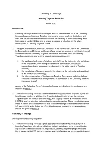
Imaging2-152.2.2 The refractive indexMany materials have a well-characterizedMaterialrefractive index, but these indices dependVacuumstrongly upon the wavelength of light.Therefore, any numeric value for the index is Air @ STPmeaningless unless the associated wavelength Water (20 C)is specified.1Acrylic glassn at λ 589.3 nm1 (exactly)1.00029261.3331.490 - 1.492There are also weaker dependencies on Crown glass (pure) 1.50 - 1.54temperature, pressure, and stress, as well on the Flint glass (pure)1.60 - 1.62precise material compositions (including theCrown glass (impure) 1.485 - 1.755presence of impurities and dopants). However,these variations are usually at the percent level Flint glass (impure) 1.523 - 1.925or less. Thus, it is especially important to cite Diamond2.419the source for an index measurement if highGallium(III) arsenide 3.927precision is claimed. http://www.luxpop.com/lists the index for a number of materials.Table 2-1. The refractive index of some materials.In general, an index of refraction is a complex number with both a real and imaginarypart, where the latter indicates the strength of the relative absorption loss at a particularwavelength. The imaginary part is sometimes called the extinction coefficient k.2.2.2.1 The Sellmeier equation n (λ ) 1 iBi λ2 λ2 Ci BK7silicaCaF21,7Index of refractionDeduced in 1871 by W. Sellmeier, thisequation models dispersion in arefractive medium, and is an empiricalrelationship between the refractiveindex n and the wavelength λ for aparticular transparent medium. Theusual form of the Sellmeier equation forglasses is:21,42004006008001000120014001600wavelength (nm)Figure 2-13. The refractive index of BK7,silica, and CaF2 as a function of wavelength.The coefficients B1,2,3 and C1,2,3 are usually quoted for λ in micrometers. Note that this λis the vacuum wavelength; not that in the material itself, which is λ/n(λ).1The refractive index value is given for the D line of sodium at 589 nm at 25 C unless otherwise specified. Fritz Albregtsen 2008
2-16Reflection, refraction, diffraction, and scattering2.2.2.2 The Fresnel equationsWhen light moves from a medium with refr
returned in the direction from which it came. A surface can be made partially retroreflective by depositing a layer of tiny refractive spheres on it or by creating small pyramid like structures (cube corner reflection). In both cases internal reflection causes th