Transcription
Sun Blade 150 Service ManualSun Microsystems, Inc.4150 Network CircleSanta Clara, CA 95054 U.S.A.650-960-1300Part No. 816-4379-10June 2002, Revision ASend comments about this document to: docfeedback@sun.com
Copyright 2002 Sun Microsystems, Inc., 4150 Network Circle, Santa Clara, California 95054, U.S.A. All rights reserved.Sun Microsystems, Inc. has intellectual property rights relating to technology embodied in the product that is described in this document. Inparticular, and without limitation, these intellectual property rights may include one or more of the U.S. patents listed athttp://www.sun.com/patents and one or more additional patents or pending patent applications in the U.S. and in other countries.This document and the product to which it pertains are distributed under licenses restricting their use, copying, distribution, anddecompilation. No part of the product or of this document may be reproduced in any form by any means without prior written authorization ofSun and its licensors, if any.Third-party software, including font technology, is copyrighted and licensed from Sun suppliers.Parts of the product may be derived from Berkeley BSD systems, licensed from the University of California. UNIX is a registered trademark inthe U.S. and in other countries, exclusively licensed through X/Open Company, Ltd.Sun, Sun Microsystems, the Sun logo, Sun Blade, SunMicrophone, SunVTS, AnswerBook2, docs.sun.com, OpenBoot, Power Management,ShowMe How, UltraSPARC, and Solaris are trademarks or registered trademarks of Sun Microsystems, Inc. in the U.S. and in other countries.All SPARC trademarks are used under license and are trademarks or registered trademarks of SPARC International, Inc. in the U.S. and in othercountries. Products bearing SPARC trademarks are based upon an architecture developed by Sun Microsystems, Inc.The Energy Star logo is a registered trademark of EPA.The OPEN LOOK and Sun Graphical User Interface was developed by Sun Microsystems, Inc. for its users and licensees. Sun acknowledgesthe pioneering efforts of Xerox in researching and developing the concept of visual or graphical user interfaces for the computer industry. Sunholds a non-exclusive license from Xerox to the Xerox Graphical User Interface, which license also covers Sun’s licensees who implement OPENLOOK GUIs and otherwise comply with Sun’s written license agreements.As an Energy Star partner, Sun Microsystems, Inc. has determined that configurations of thisproduct that bear the Energy Star Logo meet the Energy Star guidelines for energy efficiency.Use, duplication, or disclosure by the U.S. Government is subject to restrictions set forth in the Sun Microsystems, Inc. license agreements and asprovided in DFARS 227.7202-1(a) and 227.7202-3(a) (1995), DFARS 252.227-7013(c)(1)(ii) (Oct. 1998), FAR 12.212(a) (1995), FAR 52.227-19, orFAR 52.227-14 (ALT III), as applicable.DOCUMENTATION IS PROVIDED "AS IS" AND ALL EXPRESS OR IMPLIED CONDITIONS, REPRESENTATIONS AND WARRANTIES,INCLUDING ANY IMPLIED WARRANTY OF MERCHANTABILITY, FITNESS FOR A PARTICULAR PURPOSE OR NON-INFRINGEMENT,ARE DISCLAIMED, EXCEPT TO THE EXTENT THAT SUCH DISCLAIMERS ARE HELD TO BE LEGALLY INVALID.Copyright 2002 Sun Microsystems, Inc., 4150 Network Circle, Santa Clara, California 95054, Etats-Unis. Tous droits réservés.Sun Microsystems, Inc. a les droits de propriété intellectuels relatants à la technologie incorporée dans le produit qui est décrit dans cedocument. En particulier, et sans la limitation, ces droits de propriété intellectuels peuvent inclure un ou plus des brevets américains énumérésà http://www.sun.com/patents et un ou les brevets plus supplémentaires ou les applications de brevet en attente dans les Etats-Unis et dansles autres pays.Ce produit ou document est protégé par un copyright et distribué avec des licences qui en restreignent l’utilisation, la copie, la distribution, et ladécompilation. Aucune partie de ce produit ou document ne peut être reproduite sous aucune forme, parquelque moyen que ce soit, sansl’autorisation préalable et écrite de Sun et de ses bailleurs de licence, s’il y ena.Le logiciel détenu par des tiers, et qui comprend la technologie relative aux polices de caractères, est protégé par un copyright et licencié par desfournisseurs de Sun.Des parties de ce produit pourront être dérivées des systèmes Berkeley BSD licenciés par l’Université de Californie. UNIX est une marquedéposée aux Etats-Unis et dans d’autres pays et licenciée exclusivement par X/Open Company, Ltd.Sun, Sun Microsystems, le logo Sun, Sun Blade, SunMicrophone, SunVTS, AnswerBook2, docs.sun.com, OpenBoot, Power Management,ShowMe How, UltraSPARC, et Solaris sont des marques de fabrique ou des marques déposées de Sun Microsystems, Inc. aux Etats-Unis et dansd’autres pays.Toutes les marques SPARC sont utilisées sous licence et sont des marques de fabrique ou des marques déposées de SPARC International, Inc.aux Etats-Unis et dans d’autres pays. Les produits protant les marques SPARC sont basés sur une architecture développée par SunMicrosystems, Inc.L’interface d’utilisation graphique OPEN LOOK et Sun a été développée par Sun Microsystems, Inc. pour ses utilisateurs et licenciés. Sunreconnaît les efforts de pionniers de Xerox pour la recherche et le développment du concept des interfaces d’utilisation visuelle ou graphiquepour l’industrie de l’informatique. Sun détient une license non exclusive do Xerox sur l’interface d’utilisation graphique Xerox, cette licencecouvrant également les licenciées de Sun qui mettent en place l’interface d ’utilisation graphique OPEN LOOK et qui en outre se conformentaux licences écrites de Sun.LA DOCUMENTATION EST FOURNIE "EN L’ÉTAT" ET TOUTES AUTRES CONDITIONS, DECLARATIONS ET GARANTIES EXPRESSESOU TACITES SONT FORMELLEMENT EXCLUES, DANS LA MESURE AUTORISEE PAR LA LOI APPLICABLE, Y COMPRIS NOTAMMENTTOUTE GARANTIE IMPLICITE RELATIVE A LA QUALITE MARCHANDE, A L’APTITUDE A UNE UTILISATION PARTICULIERE OU AL’ABSENCE DE CONTREFAÇON.PleaseRecycle
ContentsPreface1.2.3.xxiProduct Description1–11.1Product Overview1.2Supported Sun Monitors1.3System Description1.4Replaceable ComponentsSunVTS Overview1–31–4SunVTS Description2.2SunVTS Requirements2.3SunVTS References2–12–22–23–13.1POST Overview3.2How to Use POST3.3Pre-POST Preparation3.41–62–12.1Power-On Self-Test1–43–13–23–23.3.1Setting Up a TIP Connection3.3.2Disconnecting a TIP Connection3.3.3Verifying the Baud RateViewing the POST Menus3–33–43–43–5iii
4.3.5Initializing POST3.6Maximum and Minimum POST Levels3–63.6.1diag-level Variable Set to max3–63.6.2diag-level Variable Set to min3–183.7POST Progress and Error Reporting3.8Bypassing POST3.9Resetting Variables to Default Settings3–273.10Viewing the Default NVRAM Settings3–283.11Initializing Motherboard POST3–253–27Troubleshooting Procedures3–284–14.1Power-On Failure4.2Video Output Failure4.3Hard Drive, CD-ROM, or DVD-ROM Drive Failure4.4Power Supply Test4.5DIMM Failure4.6OpenBoot PROM On-Board Diagnostics4.74–14–24–54–5Watch-Clock Diagnostic4.6.2Watch-Net and Watch-Net-All Diagnostics4.6.3Probe-IDE DiagnosticOpenBoot Diagnostics4–54–8OpenBoot Diagnostics Menu Overview4.7.2Starting the OpenBoot Diagnostics Menu4.7.3OpenBoot Diagnostics HelpHelp Command4–84–124–12Specific OpenBoot Diagnostics Tests4.7.4.1Test Command4.7.4.2Test-all Command4.7.4.3Except CommandSun Blade 150 Service Manual June ��54–134–134–144–144–9
5.6.4.7.4.4Versions Command4.7.4.5What Command4.7.4.6Printenvs Command4.7.4.7Setenv Command4.7.4.8Exit Command4–144–154–154–164–164.7.5Error Reporting in OpenBoot Diagnostics4.7.6Exiting OpenBoot Diagnostics and Resetting the OpenBoot PROMsettings 4–17Preparing for Component Removal and Replacement5.1Safety Requirements5.2Safety Symbols5.3Safety Precautions5–25–25.3.1Modification to Equipment5–25.3.2Placement of a Sun Product5–35.3.3Power Cord Connection5.3.4Electrostatic Discharge5.3.5Lithium Battery5–35–35–4Tools Required5.5Powering Off the System5.6Removing the System Cover5.7Attaching the Antistatic Wrist Strap5–45–45–65–6Removing and Replacing Major Subassemblies6.2Power g the Power Supply6–16.1.2Replacing the Power Supply6–2Cable Assemblies6–36.2.1Removing the Diskette Drive Data Cable Assembly6–36.2.2Replacing the Diskette Drive Data Cable Assembly6–4Contentsv
6.36.47.Removing the Diskette Drive Power Cable Assembly6–56.2.4Replacing the Diskette Drive Power Cable Assembly6–66.2.5Removing the Primary IDE Cable Assembly6–66.2.6Replacing the Primary IDE Cable Assembly6–76.2.7Removing the Secondary IDE Cable Assembly6–76.2.8Replacing the Secondary IDE Cable Assembly6–86.2.9Removing the Smart Card Reader Cable Assembly6–96.2.10Replacing the Smart Card Reader Cable Assembly6–106.2.11Removing the Power Switch/LED Assembly6–106.2.12Replacing the Power Switch/LED Assembly6–12Speaker Assembly6–136.3.1Removing the Speaker Assembly6–136.3.2Replacing the Speaker Assembly6–15Fan Assembly6–156.4.1Removing the Fan Assembly6–156.4.2Replacing the Fan Assembly6–16Removing and Replacing Storage Devices7.17.27.37.4vi6.2.3Diskette Drive7–17–17.1.1Removing the Diskette Drive7–17.1.2Replacing the Diskette Drive7–3Smart Card Reader7–47.2.1Removing the Smart Card Reader7–47.2.2Replacing the Smart Card Reader7–5Hard Drives7–67.3.1Removing a Primary Hard Drive7–67.3.2Replacing a Primary Hard Drive7–77.3.3Installing a Secondary Hard DriveCD-ROM or DVD-ROM DriveSun Blade 150 Service Manual June 20027–117–8
8.8.28.38.48.58.610.Removing a CD-ROM or DVD-ROM Drive7–117.4.2Replacing a CD-ROM or DVD-ROM Drive7–12Removing and Replacing the Motherboard and Related Components8.19.7.4.1CPU8–18.1.1Removing the CPU8–18.1.2Replacing the CPU8–3NVRAM/TOD8–58.2.1Removing the NVRAM/TOD8–58.2.2Replacing the NVRAM/TOD8–6DIMMs8–78.3.1Removing a DIMM8–78.3.2Replacing a DIMM8–9PCI Card8–108.4.1Removing a PCI Card8–108.4.2Replacing a PCI Card8–11Motherboard8–128.5.1Removing the Motherboard8–128.5.2Replacing the Motherboard8–14Riser Board8–168.6.1Removing the Riser Board8–168.6.2Replacing the Riser Board8–17Finishing Component Replacement9.1Replacing the System Cover9.2Powering On the System9–19–19–2OpenBoot Emergency Procedures10.18–110–1OpenBoot Emergency Procedures for Systems With Standard (Non-USB)Keyboards 10–1Contentsvii
10.2OpenBoot Emergency Procedures for Systems With USB Keyboards10.2.1Stop-A Functionality10.2.2Stop-N Equivalent Functionality10.2.3Stop-F Functionality10–310.2.4Stop-D Functionality10–410–210–2A. Product Specifications and Reference InformationA.1Physical SpecificationsA.2Electrical SpecificationsA–2A.3Acoustic SpecificationsA–2A.4Environmental E Cabling ConfigurationA.5.2CD-ROM and DVD-ROM Jumper SettingsA.5.3CD Handling and UseA–4A–5A–5A.5.3.1Inserting a CD Into the CD-ROM or DVD-ROM DriveA–5A.5.3.2Ejecting a CD From the CD-ROM or DVD-ROM DriveA–6A.5.3.3Cleaning the CD-ROM or DVD-ROM DriveA.5.3.4Handling and Storing CDsModem Setup SpecificationsSetting Up the ModemA.6.2Changing the Serial Port SpeedA.6.3Modem .3.2Modem Switch Settings (AT Commands)B–1Sun Blade 150 Service Manual June 2002A–6A–6A.6.1B. Signal DescriptionsviiiA–1Clearance Requirements for Proper CoolingReference Information10–2A–9A–9
B.1Power Supply ConnectorsB–2B.2Universal Serial Bus ConnectorB.3IEEE 1394 ConnectorB.4Twisted-Pair Ethernet ConnectorB–4B–5B–6B.4.1TPE Cable-Type ConnectivityB.4.2External UTP-5 Cable LengthsB.5Serial Port ConnectorB.6Parallel Port ConnectorB.7Audio ConnectorsB.8Video ConnectorB–15C. Functional 3Riser BoardC.4Jumper DescriptionsC.5Motherboard ComponentsC–1C–3C–4C–5C.5.1CPUC.5.2IChip2 ASICC.5.3SouthBridge �7C.5.3.1Super I/O FunctionsC.5.3.2PCI IDE ControllerC.5.3.3AC97 Compliant Audio InterfaceC.5.3.4SMBus InterfacePCI GraphicsC–7C–9C–10C–10C.5.4.1ATI Rage XL ASICC–10C.5.4.2Graphics MemoryC–10PCIO-2.x ASICC.5.5.1C–9C–10EthernetC–10Contentsix
C.5.5.2USBC.5.5.3IEEE 1394PCI to PCI Bridge ASICC.5.7Flash PROMC.5.8Smart Card InterfaceC.5.9NVRAM/TODReset k GenerationC.7.2OpenBoot PROM JumpersPower ControlC.8.2C.8.3C.8.4C–13CPU Speed SelectionC–15C.8.1.1Powering on the SystemC–15C.8.1.2Interrupting the systemC–15C.8.1.3Forcing the System to Power-Off During SoftwareHang C–16Power-On and Power-Off 16On-Board VRMC–16C–16C.8.3.1On-Board VRM requirementsC.8.3.2Power-On BeepC.8.3.3Power-On LED ControlC–17Optional Secondary Hard DriveMemory ArchitectureSDRAM Address MultiplexingC.9.2DIMMsC–17C–20C–21Speed and TimingSDRAM DIMM ConfigurationSun Blade 150 Service Manual June 2002C–17C–18C.9.1C.9.3C–14C–15Power C–11C–21C–21C–17
C.9.3.1C.10DIMM Memory AddressingAddress MappingC–22C.10.1 Port AllocationsC–22C.10.2 PCI Address AssignmentsC.11PCI Bus A Address AssignmentsC–23C.10.2.2PCI Bus B Address AssignmentsC–24InterruptsPowerC–25Energy Star Power Consumption Tier 1C.12.1.2Energy Star Tier 2, Guideline BC–26D. Special ProceduresD–1Disabling Power ManagementE.2C–26C–26D–1D.1.1Disabling Hard Drive Power ManagementD.1.2Disabling all System Power ManagementSetting the Default Console DisplayE. Using USB DevicesE.1C–25C.12.1.1C.12.2 USBD.2C–25C–25C.12.1 Energy StarD.1C–23C.10.2.1C.11.1 Interrupt InterfaceC.12C–22D–1D–2D–2E–1USB Keyboard and MouseE–1E.1.0.1KeyboardsE.1.0.2Mouse DevicesUSB Power ManagementE–2E.2.1Storage DevicesE–3E.2.2Printer DevicesE–3E.2.3Audio DevicesE–3E.2.4Hot PluggingE–1E–2E–3Contentsxi
E.2.5CablingE.2.6Devices SupportedE.2.7Man Pages AvailableGlossaryIndexxiiGlossary–1Index–1Sun Blade 150 Service Manual June 2002E–4E–4E–4
FiguresFIGURE P-1Link to Multimedia Instructions xxiFIGURE 1-1Sun Blade 150 SystemFIGURE 1-2Front Panel Overview1–5FIGURE 1-3Back Panel Overview1–5FIGURE 1-4Sun Blade 150 System Replaceable PartsFIGURE 3-1Setting Up a TIP ConnectionFIGURE 5-1Front Panel Power SwitchFIGURE 5-2Removing the System Cover 5–6FIGURE 5-3Attaching the Wrist Strap to the ChassisFIGURE 6-1Removing and Replacing the Power Supply 6–2FIGURE 6-2Removing and Replacing the Diskette Drive Data Cable AssemblyFIGURE 6-3Removing and Replacing the Diskette Drive Power Cable AssemblyFIGURE 6-4Removing and Replacing the Primary IDE Cable Assembly 6–7FIGURE 6-5Removing and Replacing the Secondary IDE Cable AssemblyFIGURE 6-6Removing and Replacing the Smart Card Reader Cable Assembly 6–9FIGURE 6-7Removing the Front BezelFIGURE 6-8Removing and Replacing the Power Switch/LED Assembly 6–12FIGURE 6-9Removing and Replacing the Speaker AssemblyFIGURE 6-10Removing and Replacing the Fan AssemblyFIGURE 7-1Removing and Replacing the Peripheral Assembly 16–146–16xiii
xiv7–3FIGURE 7-2Removing the Diskette DriveFIGURE 7-3Removing and Replacing the Smart Card Reader 7–5FIGURE 7-4Removing and Replacing a Primary Hard DriveFIGURE 7-5Installing a Secondary Hard DriveFIGURE 7-6Secondary Hard Drive Cabling Configuration 7–11FIGURE 7-7Removing and Replacing a CD-ROM or DVD-ROM Drive 7–12FIGURE 8-1Removing and Replacing the CPU 8–3FIGURE 8-2JP3 OpenBoot PROM Jumper Settings for 650 MHz and 550 MHz CPUsFIGURE 8-3Removing and Replacing the NVRAM/TOD 8–6FIGURE 8-4DIMM Installation Order 8–8FIGURE 8-5Removing and Replacing a DIMM 8–9FIGURE 8-6Removing and Replacing a PCI Card 8–11FIGURE 8-7Removing and Replacing the Motherboard 8–14FIGURE 8-8JP1/JP2 Jumper Settings for the Flash PROMFIGURE 8-9Removing and Replacing the Riser Board 8–17FIGURE 9-1Replacing the System CoverFIGURE 9-2System Power Switch 9–2FIGURE A-1Minimum Clearance for System CoolingFIGURE A-2IDE Cabling ConfigurationFIGURE A-3External and Internal Serial PortsFIGURE B-1Power Supply Connector J501 Pin ConfigurationFIGURE B-2Secondary Power Supply Connector J505 Pin ConfigurationFIGURE B-3USB Connector J17, J18 Pin ConfigurationFIGURE B-4IEEE 1394 Connector J20, J30 Pin Configuration B–5FIGURE B-5TPE Connector J19 Pin ConfigurationFIGURE B-6Serial Port Connector J36 Pin Configuration B–8FIGURE B-7Riser Board Serial Port Pinouts (J13)FIGURE B-8Accessing the Second Serial Port Through a PCI Card Slot B–10FIGURE B-9Serial and Video Port Connector Extensions B–11FIGURE B-10Parallel Port Connector J9 Pin Configuration B–12Sun Blade 150 Service Manual June 3B–4B–6B–98–4
B–14FIGURE B-11Audio Connector ConfigurationFIGURE B-12Video Connector J37 Pin Configuration B–15FIGURE B-13Serial and Video Port Connector Extensions B–16FIGURE C-1Sun Blade 150 System Functional Block DiagramFIGURE C-2Motherboard Layout DiagramFIGURE C-3Riser Board Layout Diagram, Side 1 C–4FIGURE C-4Riser Board Layout Diagram, Side 2 C–5FIGURE C-5External and Internal Serial PortsFIGURE C-6Audio Circuit Functional Block Diagram C–9FIGURE C-7PROM Interface C–12FIGURE C-8Smart Card Interface Header C–12FIGURE C-9JP3 OpenBoot PROM Jumper Settings for 550 MHz and 650 MHz CPUsFIGURE C-10Secondary Hard Drive Cabling Configuration C–17FIGURE C-11Sun Blade 150 Memory Block Diagram C–19FIGURE C-12SDRAM Address MultiplexingC–2C–3C–8C–15C–20Figuresxv
xviSun Blade 150 Service Manual June 2002
Tables1–4TABLE 1-1Supported Sun MonitorsTABLE 1-2Sun Blade 150 System Physical DimensionsTABLE 1-3Back Panel Description and Connector Symbols 1–6TABLE 1-4Sun Blade 150 Replaceable ComponentsTABLE 4-1Internal Drives Identification 4–3TABLE 4-2DIMM Physical Memory AddressTABLE 8-1Flash PROM Jumper Settings 8–15TABLE A-1Sun Blade 150 Physical Specifications A–1TABLE A-2Sun Blade 150 System Electrical SpecificationsTABLE A-3Acoustic Specifications A–2TABLE A-4Sun Blade 150 System Environmental RequirementsTABLE B-1Power Supply Connector J501 Pin AssignmentsB–2TABLE B-2Power Supply Connector J505 Pin AssignmentsB–3TABLE B-3USB Connector J17, J18 Pin Assignments B–4TABLE B-4IEEE 1394 Connector J20, J30 Pin AssignmentsTABLE B-5TPE Connector J19 Pin AssignmentsTABLE B-6TPE UTP-5 CablesTABLE B-7Serial Port Connector J36 Pin AssignmentsTABLE B-8Riser Board Serial Port Connector J13 Pin AssignmentsTABLE B-9Parallel Port Connector J9 Pin Assignments 8B–9xvii
xviiiTABLE B-10Audio Connector Line Assignment B–14TABLE B-11Video Connector J37 Pin AssignmentsTABLE C-1Riser Board Connectors, Side 1C–4TABLE C-2Riser Board Connectors, Side 2C–5TABLE C-3Clock FrequenciesTABLE C-4DIMMs Performance RangeTABLE C-5SDRAM size options (DIMMs only)TABLE C-6DIMM Physical Memory AddressTABLE C-7Port Allocations C–23TABLE C-8PCI Address AssignmentsTABLE C-9Openboot PROM/Flash PROM Address Assignments C–24TABLE C-10Maximum Sleep Mode Power C–26B–15C–14Sun Blade 150 Service Manual June 2002C–21C–21C–22C–23
Code Examples3-7CODE EXAMPLE 3-1diag-level Variable Set to maxCODE EXAMPLE 3-2diag-level Variable Set to min 3-19CODE EXAMPLE 3-3Typical POST Error Message: DIMM Failure 3-25CODE EXAMPLE 4-1Watch-clock Diagnostic 4-6CODE EXAMPLE 4-2Watch-Net Diagnostic Output MessageCODE EXAMPLE 4-3Watch-Net-All Diagnostic Output Message 4-7CODE EXAMPLE 4-4Probe-IDE Diagnostic Output Message 4-7CODE EXAMPLE 4-5OpenBoot Diagnostics Menu 4-9CODE EXAMPLE 4-6Reset Verification 4-10CODE EXAMPLE 4-7OpenBoot Diagnostics Menu 4-12CODE EXAMPLE 4-8OpenBoot Diagnostics Help CommandsCODE EXAMPLE 4-9Test CommandCODE EXAMPLE 4-10Except CommandCODE EXAMPLE 4-11Versions CommandCODE EXAMPLE 4-12What CommandCODE EXAMPLE 4-13Printenvs CommandCODE EXAMPLE 4-14Setenv CommandCODE EXAMPLE 4-15Exit CommandCODE EXAMPLE 4-16Example of Error Testing Output 4-16CODE EXAMPLE 10-1Resetting Default NVRAM Variables 10-24-64-134-134-144-144-154-154-164-16xix
xxSun Blade 150 Service Manual June 2002
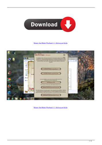
PrefaceThe Sun Blade 150 Service Manual provides detailed procedures that describe theremoval and replacement of replaceable parts in the Sun Blade 150 computersystem. The service manual also includes information about the use andmaintenance of the system. This book is written for technicians, systemadministrators, authorized service providers (ASPs), and advanced computer systemend users who have experience troubleshooting and replacing hardware.About the Multimedia Links in ThisManualRemoval and replacement procedures for selected system components are alsoillustrated with interactive multimedia audio and video instructions in theSun Blade 150 Hardware Documentation CD-ROM, which is linked to the onlineversion of this manual. These multimedia links can be accessed wherever you seethe film-clip icon Shown in FIGURE P-1 .FIGURE P-1Link to Multimedia Instructionsxxi
How This Book Is OrganizedChapter 1 describes the major components of the system.Chapter 2 describes the execution of individual tests for verifying hardwareconfiguration and functionality.Chapter 3 describes the execution of Power-on Self-test (POST) and providesexamples of POST output patterns.Chapter 4 provides troubleshooting advice and suggested corrective actions forhardware problems.Chapter 5 explains how to work safely when replacing system components. ThisChapter provides procedures for powering off the system, removing the systemcover, and attaching the wrist strap.Chapter 6 provides procedures for removing and replacing major subassemblies.Chapter 7 provides procedures for removing and replacing storage devices.Chapter 8 provides procedures for removing and replacing the motherboard andrelated components.Chapter 9 provides procedures for replacing the system cover and powering on thesystem.Chapter 10 provides OpenBoot Emergency procedures specific to the USBkeyboard.Appendix A provides specifications on power and environment, system dimensions,weight, memory mapping, and peripheral component interconnect (PCI) card slots.Appendix B provides signal descriptions, instructions for connecting the system unitto a 10BASE-T/100BASE-T twisted-pair Ethernet (TPE) local area network (LAN),and modem settings for systems used in specific network telecommunicationapplications.Appendix C provides functional descriptions of the system and components.Appendix D provides procedures for setting the defualt console display and fordisabling power management.Appendix E provides information on USB devices, special key commands, relatedpower management information, and USB man pages.xxii Sun Blade 150 Service Manual June 2002
Using UNIX CommandsThis document may not contain information on basic UNIX commands andprocedures such as shutting down the system, booting the system, and configuringdevices.See one or more of the following for this information: Solaris Handbook for Sun Peripherals AnswerBook2 online documentation for the Solaris software environment Other software documentation that you received with your systemThe Sun Blade 150 Getting Started Guide gives more information on how to use thesedocuments.Typographic ConventionsTypefaceMeaningExamplesAaBbCc123The names of commands, files,and directories; on-screencomputer outputEdit your .login file.Use ls -a to list all files.% You have mail.AaBbCc123Text that you type (whencontrasted with the on-screencomputer output)% suPassword:AaBbCc123Book titles, new words or terms,words to be emphasizedRead Chapter 6 in the User’s Guide.These are called class options.You must be superuser to do this.Command-line variable; replacewith a real name or valueTo delete a file, type rm filename.Prefacexxiii
Shell PromptsShellPromptC shellmachine name%C shell superusermachine name#Bourne shell and Korn shell Bourne shell and Korn shell superuser#Accessing Sun Documentation OnlineYou can obtain copies of Sun Blade 150 documents at the following re/docs/Workstation Products/Workstations/Sun Blade Workstations/index.htmlThe docs.sun.comSM web site enables you to access Sun technical documentationon the Web. You can browse the docs.sun.com archive or search for a specific booktitle or subject at:http://docs.sun.comSunService Solution CenterFor answers to your technical questions, contact your nearest SunServiceSM SolutionCenter. Phone numbers and contact information for SunService Centers can be foundat this web n.htmlxxivSun Blade 150 Service Manual June 2002
Sun Welcomes Your CommentsWe are interested in improving our documentation and welcome your commentsand suggestions. You can email your comments to us at:docfeedback@sun.comPlease include the part number (816-4379-10) of your document in the subject line ofyour email.Prefacexxv
xxviSun Blade 150 Service Manual June 2002
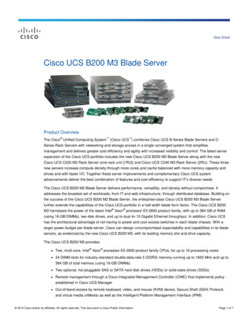
CHAPTER1Product DescriptionThe Sun Blade 150 workstation is a uniprocessor system that uses the UltraSPARCIIi processor. FIGURE 1-1 shows the Sun Blade 150 workstation.This chapter contains the following topics: Section 1.1,Section 1.2,Section 1.3,Section 1.4,“Product Overview” on page 1-3“Supported Sun Monitors” on page 1-4“System Description” on page 1-4“Replaceable Components” on page 1-61-1
FIGURE 1-11-2Sun Blade 150 SystemSun Blade 150 Service Manual June 2002
1.1Product OverviewThe Sun Blade 150 system provides the following features: Desktop-style system enclosure Power supply: 250-watt CPU options: 550-MHz or 650-MHz UltraSPARC-IIi processor with 512-Kbyteinternal cache, heatsink, and fan Hard drives: One 40 gigabyte, 7,200 RPM hard drive with ATA66 interface Additional hard drive available as an optional component Diskette drive: 1.44-megabyte (Mbyte) manual eject Smart card reader One optical drive: CD-ROM drive or DVD-ROM drive Audio: CD-quality PCI connectors: 33-MHz, 32-bit peripheral component interconnect (PCI) Three long PCI connectors accept both long and short PCI cards ATI Rage XL on-board graphics, 8 Mbyte RAM Two serial ports One serial port on the chassis back panel One serial port on the riser card (requires one PCI slot to access the connector) One parallel port Ethernet: 10-megabit/100-megabit per second Two IEEE 1394 ports (Firewire) Four USB ports, (two are required for keyboard and mouse) Keyboard: SunTM USB Type-6 AT 101 layout Mouse: Sun USB 3-button, crossbow mouseChapter 1Product Description1-3
1.2Supported Sun MonitorsThe monitors listed in TABLE 1-1 can be used with the Sun Blade 150 system.For more detailed information on these monitors contact your Sun representative orsee the following web ripherals/TABLE 1-11.3Supported Sun MonitorsI/O DeviceDescription17-inch color CRT monitorSupports resolutions up to 1152x90018.1-inch TFT LCD color monitor1280x1024 resolution21-inch CRT color monitor, flatdisplaySupports resolutions up to 1600x120024.1-inch LCD flat panel monitorSupports resolutions up to 1920x1200System DescriptionSystem components are housed in a desktop-style enclosure. Overall chassisdimensions for the Sun Blade 150 system are listed in TABLE 1-2.TABLE 1-2Sun Blade 150 System Physical DimensionsWidthHeightDepth17.52 inches(44.5 cm)4.65 inches(11.8 cm)18.00 inches(45.7 cm)System electronics are contained on a single plug-in printed circuit board(motherboard). The motherboard contains the CPU, memory modules, systemcontrol application-specific integrated circuits (ASIC), and I/O ASICs. Themotherboard plugs into a riser board that provides the system power and integrateddrive electronics (IDE) hard drive data interface. FIGURE 1-2 and FIGURE 1-3 show theSun Blade 150 system front and back panels.1-4Sun Blade 150 Service Manual June 2002
23541FIGURE 1-2Front Panel Overview1. Power switch2. Power-indicator LED3. Smart card reader4. 3.5-inch diskette drive5. 5.25-inch optical drive bay (CD-ROM or DVD-ROM)1FIGURE 1-323456789Back Panel OverviewChapter 1Product Description1-5
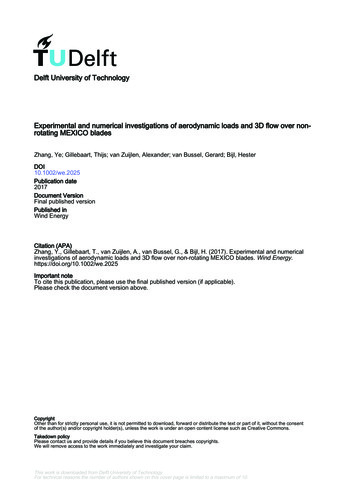
TABLE 1-3Back Panel Description and Connector SymbolsItem inFigure 1-3Explanation1Power connectorNone2PCI card slot 3 (33 MHz)PCI-32PCI card slot 2 (33 MHz)PCI-22PCI card slot 1 (33 MHz)PCI-13Universal serial bus (USB) connectors (four)4Twisted-pair Ethernet (TPE) connector5IEEE 1394 connectors (two)6VGA video connector7Parallel connector, DB-258Serial connector (RS-232)9Audio module headphones connector9Audio module line-out connector9Audio module line-in connector9Audio module microphone connectorBack Panel SymbolSERIAL.1.4Replaceable ComponentsThis section lists the replaceable components for the Sun Blade 150 system. Thenumbered components in FIGURE 1-4 correlate to the numbered components listed inTABLE 1-4. Consult your authorized Sun sales representative or service provider toconfirm a part number before ordering a replacement part.1-6Sun Blade 150 Service Manual June 2002
15*14*116*217*18*319*1320*412511106789FIGURE 1-4Sun Blade 150 System Replaceable PartsChapter 1Product Description1-7
TABLE 1-4Sun Blade 150 Replaceable ComponentsItemComponentDescription1CD-ROM driveCD-ROM drive or DVD-ROM drive2Hard drive (second drive is optional)Hard disk drive3Smart card readerSmart card reader with enclosure4Manual eject diskette driveInternal diskette drive5Speaker assemblySystem speaker with cable6Central processing unit (CPU)550 MHz or 650 MHz, 512-Kbyte internal cache7NVARAM/TODNonvolatile RAM/Time of day8128-Mbyte DIMM128-Mbyte DIMM8256-Mbyte DIMM256-Mbyte DIMM8512-Mbyte DIMM512-Mbyte DIMM9MotherboardSystem main logic board10Fan assemblySystem cooling fan with cable11PCI cardGeneric PCI card12Riser board3-slot PCI expansion and power interface card13Power supply250-watt power supply with power cable*Cable kit (items with asterisk)Cables for major components14*Secondary IDE cableSecondary HDD and riser board IDE2 cable15*Primary IDE cablePrimary HDD, CD/DVD-ROM, riser board IDE1 cable16*Hard drive and optical drive power cableCD/DVD-ROM, primary hard drive, secondary harddrive power cable17*Power switch and LED cablePower switch, L
Sun Microsystems, Inc. 4150 Network Circle Santa Clara, CA 95054 U.S.A. 650-960-1300 Send comments about this document to: docfeedback@sun.com Sun Blade