Transcription
Alawneh, Matarneh, and El-Ashri2018 PCI/NBCTHE WORLD’S FIRST 3D–PRINTED OFFICE BUILDING IN DUBAIMusa Alawneh, Ph.D, P.E, e.construct, Fz-LLC, Dubai, United Arab EmiratesMotasem Matarneh, B.S., M.S, e.construct, Fz-LLC, Dubai, United Arab EmiratesSameh El-Ashri, B.S., M.S., e.construct, Fz-LLC, Dubai, United Arab EmiratesABSTRACTThe Office of the Future was built in the city of Dubai in the United Arab Emirates, inJanuary 2016, using 3D- printed concrete elements. The office is approximately 2,000 squarefeet and was printed using a 20-feet tall 3D printer in China. Several precast techniques wereadopted in the design and construction of the Office of the Future. The 3D printed cassettes(segments) were shipped and assembled on site in Dubai. The 3D printed cassettes weresupported on cast-in-place concrete strip footing. The assembling and erection of thecassettes was done in just few days. This case study will provide an overview of the 3Dprinted concrete technology. The properties of 3D printed material will also be presented.The special design consideration will be discussed including the shipping, handling anderection. The cassettes were tested in Suzhou (China) and Dubai (UAE) prior to erection toverify the serviceability and strength performance. The paper will be concluded with outlookon the future for adopting the 3D printed concrete in large scale projects and the requiredresearch in order to enhance the current 3D printed technologyKeywords: 3D Printed concrete, cassette, testing, Post-tensioning.
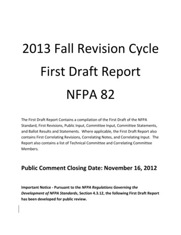
Alawneh, Matarneh, and El-Ashri2018 PCI/NBCINTRODUCTION:Three dimensional (3D) printing or Additive Manufacturing (AM) is a process of building a3D object by adding layer-upon-layer of material based on 3D digital file. The AM firstdeveloped in 1987 with stereolithography (SL) from 3D system, a process that solidifies thinlayers of ultraviolet (UV) light-sensitive liquid polymer using a laser1. The 3D printedmaterial could be plastic, metal, concrete or any other type of composite material. Accordingto ASTM F422, the manufacture process of 3D printing is categorized as follows: Direct Metal laser sintering (DMLS)Direct Energy depositionFused Deposition modelingLaser Sintering (LS)Material ExtrusionMaterial JettingPowder bed fusionThe common type that have been used in 3D printed concrete is based on material extrusionwhich is introduced by Contour Crafting company. The first publications on the printedconcrete can be found in 1998 by Khoshnevis (University of Southern California)3 andsignificant progress has been done worldwide since that date. Contour crafting methodologyutilizes a robotic fabrication system that use gantry frame to deposit a low-slump compositeconcrete material in layers to produce structural elements for housing.There are two schools of thought within 3D concrete printing which are best summarized as"Factory vs. Site." Previous research from the University of Southern California focusedmainly on site production of 3D printed elements. This focus offers a series of advantagesand disadvantages. The site based approach allows for less transport, freedom of larger unitsand a less modular approach. However, this approach requires significant mobilization,terrain limitations, climate limitations and concerns about the security of highly sensitiveintellectual property. The factory bases approach utilized on this project provided a climatecontrolled environment which enabled production to proceed at any point in time, acentralized location where the project team could inspect the building elements, etc.There are several advantages for the 3D printed concrete; 1) high speed of construction; 2) noneed for formwork; 3) less number of labour; 4) great increase of freedom of design; 5) costsaving compared to conventional construction. However, several challenges still exist as theCC still in development stage.PROJECT DESCRIPTION:The Office of the Future is located in Dubai, United Arab Emirates (U.A.E). The office wasbuilt as part of the Dubai ruler vision to build the first 3D printed concrete office in the worldin Dubai4. The total area of the office is approximately 2,000 square feet. It consists of 4champers (cassettes) that arranged in the way that open to each other and provide elegantexterior perspective. In addition to two separate cassettes. Figure 1 shows the three
Alawneh, Matarneh, and El-Ashri2018 PCI/NBCdimensional perspective of the building. The building layout and typical cross-section of thebuilding are shown in Figures 2 and 3, respectively.The superstructure was 3D printed while the substructure was conventional cast-in-place(CIP) concrete. Each cassette was divided into two parts: bottom and top parts. The shape ofeach Cassatt is a U-shape with maximum length, height, and width of 8.1m, 2.1m and 2.1m,respectively. These dimensions were determined based on the 3D printer and shippinglimitations.Fig. 1: 3D architectural Perspective
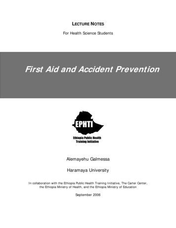
Alawneh, Matarneh, and El-Ashri2018 PCI/NBCFig. 2: Office Building LayoutFig. 3: Building Cross-sectionSTRUCTURAL SYSTEM:The member size and geometry were selected to suit the 3D printer capabilities. The concretelayer dimension that can be printed depends on the printer nozzle size. The available printercan print concrete layer up to 50mm wide by 20mm thick. Accordingly, the structural systemwas formed by a concrete truss with member size of 50mm wide. There was no limitation onthe member geometry since the printer nozzle would follow the geometry from the 3D digitalmodel.The superstructure of The Office of the Future was designed to be fully 3D printed concrete.Each cassata was divided into segments. Each segment consists of two parts: bottom and topparts. The shape of each segment is a U-shape with maximum length, height, and width of8.1m, 2.1m and 2.1, respectively. These dimensions were determined based on the 3D printerand shipping limitations. Joints between segments were filled with grout and longitudinalpost-tensioning (PT) were used to connect the segments together. The longitudinal PT werepassed within the void of the cassette which later filled with grout.The available current printer is capable of printing concrete paste which has a low tensileconcrete strength (about10% of its compression strength). The challenge was how to enhancethe 3D printed concrete element to sustained the flexural stresses. Therefore, it was proposedto add steel reinforcement manually between the concrete layers during the printing process.The steel reinforcement was also prefabricated and welded to form the shape of the concretetruss, refer to Figures 4 and 5 for concrete and steel truss dimensions; respectively.
Alawneh, Matarneh, and El-AshriFig. 4: Concrete truss dimensions (mm)Fig. 5: Steel trussFig. 6: Prefabricated rebar steel truss2018 PCI/NBC
Alawneh, Matarneh, and El-Ashri2018 PCI/NBCFig. 7: 3D printed cassette during fabrication. Steel rebar truss was placed manually betweenthe 3D printed concrete layersThe design was not finalized until the full scale testing of typical cassettes was carried out.This was due to the fact that there were highly uncertainty in material mix consistency,printing layer dimensions, curing, and bond between steel truss & concrete printed layers.After printing a few cassettes, a team of structural engineers from e.construct5 visited theproduction facility in China and carried out full inspection and full scale testing. One cassettewas tested to failure load and two cassettes were tested as per ACI318-11 testing loadrecommendation. Refer to Figures 8 to 10 for cassette during testing load.Fig. 8: 3D printed top cassette during testing
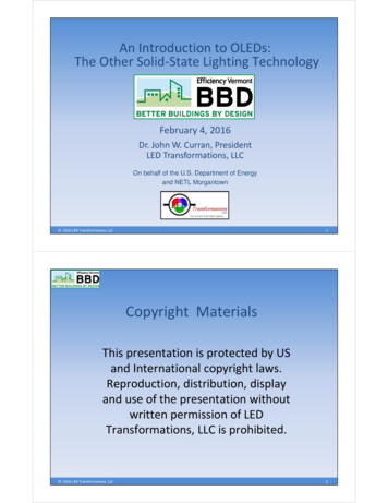
Alawneh, Matarneh, and El-Ashri2018 PCI/NBCFig. 9: 3D printed bottom cassette at the failure testing loadFig. 10: cracking pattern at the mid span during testing.The testing results indicated low structural performance of the printed concrete cassettes. Ithas been noted that the thickness of the chords is variable. It was ranged between 35 to45mm, so in the design, 35mm width was considered as a structural stiffness and 45mm wasused for self-weight calculation. The flexural capacity of the cassette was very low comparedto the theoretical predication. The specimen also had a lot of cracks under initial testingloading and undergone large deformation. The failure mechanism has been largely influencedby the bonding of the reinforcement with the printed concrete. A flexure failure occurred atthe bottom/base of printed cassette and compression block failure occurred at the top pf theprinted cassette. The bonding was good at bottom/base of the print where the chords size wasthe largest (45mm) due consolidated under the self-weight of the upper layers. The top of theprint showed less bonding where concrete consolidation was minimal and chord size reachedas low as 35mm.As a conclusion from the testing results, it was decided to add external transverse posttensioning (PT) to enhance the flexural capacity of the top cassette. In the bottom cassette,two strip footings were introduced between the original two strip footings. Furthermore, itwas decided that all the cassette shall be full scale tested on Dubai before can be approved tobe erected on site.
Alawneh, Matarneh, and El-AshriFig. 11: Failure mechanism at top of the print.Fig. 12: Failure mechanism at base of the print.2018 PCI/NBC
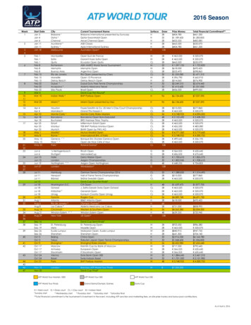
Alawneh, Matarneh, and El-Ashri2018 PCI/NBC3D CONCRETE PRINTER:The concrete cassettes were printed in China by Chinese based company Winsun 6. The 3DPrinter is 20 feet tall, 33 feet wide and 132 feet long. The printer is used robotics headconnecting with computer that fusion concrete paste material that laid layer by layer. Thewidth of the concrete layer is around 50mm by 20mm thickness. Due to confidentially, nophoto was allowed to be taken for the printer; however, refer to Figure 11 for the schematicdiagram for the printer.e.construct the design engineering firm based on Dubai was developed the 3D digital modelusing Rhino software that can be translated to the 3D printer language. The printing processtakes up to 12 hours to build each cassette.3D PRINTED CONCRETE MATERIAL:The concrete mix was developed by WinSun which they have been used it in their projects.All of their projects were built in China. The office of the Future was the first project forthem to be built outside china. The concrete mix consists of cement, water, glass fibers, andadditives.Before starting the design of The Office of the Future, six concrete samples were tested inSandberg Laboratory7. The test program comprised of five parts: Compression and tensile strengthBond strength/adhesionModulus of elasticity and thermal coefficientDensity, water absorption and permeability, drying shrinkage, wetting expansion, andfreeze thawChemical composition (petrographic and SEM examination)The structural design was based on the results of the testing for the main design parameter: Compressive strength after 28 days 31.6 MPa,Tensile splitting strength after 28 days 3.0 MPa,Modulus of elasticity after 28 days 19,500.0 MPa
Alawneh, Matarneh, and El-Ashri2018 PCI/NBCFig. 13: Side view of sample of 3D Printed wall material. It shown that the printed layer is20mmFig.14: Polished surface, backscattered electron image: view showing an area of paste withabundant un-hydrated cement grains and two un-hydrated GGBSCONSTRUCTION SEQUENCE:Stage 1: Printing the Cassettes:
Alawneh, Matarneh, and El-Ashri2018 PCI/NBCThe digital model was developed for each segment and sent to printing facility in China. Thereinforcement truss was prefabricated in China and delivered to printing facility. The printingwas taking 12 hours to complete each cassette.Fig.15: schematic diagram for concrete printing processFig. 16: placing prefabricated steel truss during printing processStage 2: Ship the CassetteEach two cassettes were loaded in container and shipped to Dubai
Alawneh, Matarneh, and El-Ashri2018 PCI/NBCFig.17: Schematic Diagram showing the shipping of the 3D printed cassettesStage 3: Inspect the cassettes prior erectionAfter delivering the printed segments to Dubai, detailed inspection was done for eachcassette. Post-tensioning rebars were added for the top cassettes to enhance the flexuralcapacity.
Alawneh, Matarneh, and El-AshriStage 4: Erect the Cassette on CIP FoundationFigure 18: erection of the segment on CIP foundationStage 5: Add Transvers Post-tensioning to Connect the CassettesFigure 19: add PT to connect the segments togetherStage 6: Grout the dowels bar between the foundation and cassette2018 PCI/NBC
Alawneh, Matarneh, and El-Ashri2018 PCI/NBCFig. 20: grout dowel bars between the cassette and CP foundationStage 7: add finishing and attach non-structural elementsFig. 21: 3D printed office during applying the external finishing. Insulation was attachedfrom outside and external finishing was applied.
Alawneh, Matarneh, and El-Ashri2018 PCI/NBCRefer to Figure 19 for the 3D printed cassette during construction. Figure 20 shows thetypical connection details.Fig. 22: 3D Printed cassette after erection. external PT bars were added to top cassette andlongitudinal PT were added to connect the segments togethera) cassette to foundation connectionb) cassette to cassette connection
Alawneh, Matarneh, and El-Ashri2018 PCI/NBCc) external PT bar to cassette connectionFig. 23: Typical connection detailsANALYSIS AND DESIGN:The analysis of the panel was done using a 2D frame analysis. Chords were modelled asbeam elements with 35mm thickness by 1000mm width. Filling grout was modeled as shellelements with stiffness reduction of 0.5 to consider the effect of shrinkage cracking. ExternalPT bars were modeled using dummy frame element and the tendon profile is modeled on itscenter8. Refer to below Figures for the geometry of the analysis model.The design live load was considered as 5.0 KN/m2 and 0.6 KN/m2 for office area and aninaccessible roof, respectively. Additional superimposed dead load for finishing wereconsidered as 1.5 KN/m2 and 2.0 KN/m2 for office finishing and water proofing,respectively. Three external PT bars 25mm diameter are used for each cassette (2.1 wide).Fig.24: Geometry of 2D Model
Alawneh, Matarneh, and El-AshriThe analysis results are shown in figures 23 to 26.Fig. 25: Beam stress under PT SW (MPa)Fig. 26 Beam Stress under Load case [SW PT SIDL LL] (MPa)Fig. 27 Plate stresses under Load case (SW PT SIDL LL) (MPa)2018 PCI/NBC
Alawneh, Matarneh, and El-Ashri2018 PCI/NBCFig. 28 Deformation values in mm due to SW SIDL LL PTCONCLUSIONS:The 3D printed concrete is a new term in structural and construction engineering. The 3Dprinting technology has started in the late of last century in different industries. Recently,there were several attempts in different locations worldwide to adopt the new technology incivil engineering applications. The 3D printed concrete offers great flexibility of elementgeometry. Dubai has just built the first 3D printed office building in the world. The authorsbelieve that building “The office of the future” is one of major milestones in 3D printedconcrete technology; yet a lot of improvements can be achieved:1- Concrete mix need to be improved to enhance the tensile capacity and henceeliminating the need to add conventional reinforcement manually during printingprocess. More research required to explore the using of ultra-high strength concrete(UHPC) in 3D concrete printing.2- Quality control procedure is required to ensure the consistently of the concrete mix.3- Curing procedure is required.4- Design methodology and new code standard is required especially for designingconcrete composite element without reinforcement.5- Connection details between printed elements shall be developed as part of printingprocess.
Alawneh, Matarneh, and El-Ashri2018 PCI/NBCREFERENCES:1- History of additive Manufacturing, wholers report 2014, Wholers Associates, Inc.2- ASTM International (F2792-12a) Standard terminology for additive manufacturingtechnologies, September 09, 2013.3- Wolfs, R.J.M, 3D Printing of Concrete Structures, Graduation thesis, EindhovenUniversity of Technology, 2015.4- Newsweek Middle East 37, June 01, 20165- e.construct, FZ, LLC, Suite 203 Building No. 4, Dubai, United Arab Emirate, Tel.: 971 4 3911015, Website: www.econstruct.ae6- WinSun, China.7- Examination and testing of printed concrete samples, Report 53952/F, Sandberg LLP,5 Carpenters place clapham high street London SW47 TD.8- Building Code Requirements for Structural Concrete (AC 318-11), AmericanConcrete Institute, Farmington Hills, MI, USA, 20119- Precast Prestressed Concrete Design Handbook, sixth edition, PCI, Chicago IL, 2012.
January 2016, using 3D- printed concrete elements. The office is approximately 2,000 square feet and was printed using a 20-feet tall 3D printer in China. Several precast techniques were adopted in the design and construction of the Office of the Future. The 3D printed cassette