Transcription
Cisco Data Center Infrastructure 2.5Design GuideCisco Validated Design—November 2, 2011Important—Updated content: The Cisco Virtualized Multi-tenant DataCenter CVD (http://www.cisco.com/go/vmdc) provides updated designguidance including the Cisco Nexus Switch and Unified Computing System(UCS) platforms.Americas HeadquartersCisco Systems, Inc.170 West Tasman DriveSan Jose, CA 95134-1706USAhttp://www.cisco.comTel: 408 526-4000800 553-NETS (6387)Fax: 408 527-0883Text Part Number: OL-11565-01
Cisco Validated DesignThe Cisco Validated Design Program consists of systems and solutions designed, tested, and documented to facilitate faster, morereliable, and more predictable customer deployments. For more information visit www.cisco.com/go/validateddesigns.ALL DESIGNS, SPECIFICATIONS, STATEMENTS, INFORMATION, AND RECOMMENDATIONS (COLLECTIVELY,"DESIGNS") IN THIS MANUAL ARE PRESENTED "AS IS," WITH ALL FAULTS. CISCO AND ITS SUPPLIERS DISCLAIM ALLWARRANTIES, INCLUDING, WITHOUT LIMITATION, THE WARRANTY OF MERCHANTABILITY, FITNESS FOR APARTICULAR PURPOSE AND NONINFRINGEMENT OR ARISING FROM A COURSE OF DEALING, USAGE, OR TRADEPRACTICE. IN NO EVENT SHALL CISCO OR ITS SUPPLIERS BE LIABLE FOR ANY INDIRECT, SPECIAL,CONSEQUENTIAL, OR INCIDENTAL DAMAGES, INCLUDING, WITHOUT LIMITATION, LOST PROFITS OR LOSS ORDAMAGE TO DATA ARISING OUT OF THE USE OR INABILITY TO USE THE DESIGNS, EVEN IF CISCO OR ITS SUPPLIERSHAVE BEEN ADVISED OF THE POSSIBILITY OF SUCH DAMAGES.THE DESIGNS ARE SUBJECT TO CHANGE WITHOUT NOTICE. USERS ARE SOLELY RESPONSIBLE FOR THEIRAPPLICATION OF THE DESIGNS. THE DESIGNS DO NOT CONSTITUTE THE TECHNICAL OR OTHER PROFESSIONALADVICE OF CISCO, ITS SUPPLIERS OR PARTNERS. USERS SHOULD CONSULT THEIR OWN TECHNICAL ADVISORSBEFORE IMPLEMENTING THE DESIGNS. RESULTS MAY VARY DEPENDING ON FACTORS NOT TESTED BY CISCO.CCVP, the Cisco Logo, and the Cisco Square Bridge logo are trademarks of Cisco Systems, Inc.; Changing the Way We Work, Live,Play, and Learn is a service mark of Cisco Systems, Inc.; and Access Registrar, Aironet, BPX, Catalyst, CCDA, CCDP, CCIE, CCIP,CCNA, CCNP, CCSP, Cisco, the Cisco Certified Internetwork Expert logo, Cisco IOS, Cisco Press, Cisco Systems, Cisco SystemsCapital, the Cisco Systems logo, Cisco Unity, Enterprise/Solver, EtherChannel, EtherFast, EtherSwitch, Fast Step, Follow MeBrowsing, FormShare, GigaDrive, GigaStack, HomeLink, Internet Quotient, IOS, iPhone, IP/TV, iQ Expertise, the iQ logo, iQ NetReadiness Scorecard, iQuick Study, LightStream, Linksys, MeetingPlace, MGX, Networking Academy, Network Registrar, Packet,PIX, ProConnect, RateMUX, ScriptShare, SlideCast, SMARTnet, StackWise, The Fastest Way to Increase Your Internet Quotient, andTransPath are registered trademarks of Cisco Systems, Inc. and/or its affiliates in the United States and certain other countries.All other trademarks mentioned in this document or Website are the property of their respective owners. The use of the word partnerdoes not imply a partnership relationship between Cisco and any other company. (0612R)Cisco Data Center Infrastructure 2.5 Design Guide 2007 Cisco Systems, Inc. All rights reserved.
CONTENTSCHAPTER1Data Center Architecture Overview1-1Data Center Architecture Overview1-1Data Center Design Models 1-3Multi-Tier Model 1-3Server Cluster Model 1-5HPC Cluster Types and InterconnectsLogical Overview 1-8Physical Overview 1-9CHAPTER2Data Center Multi-Tier Model Design1-62-1Data Center Multi-Tier Design Overview2-2Data Center Core Layer 2-3Recommended Platform and Modules 2-3Distributed Forwarding 2-4Traffic Flow in the Data Center Core 2-4Data Center Aggregation Layer 2-6Recommended Platforms and Modules 2-6Distributed Forwarding 2-8Traffic Flow in the Data Center Aggregation Layer 2-8Path Selection in the Presence of Service Modules 2-8Server Farm Traffic Flow with Service Modules 2-10Server Farm Traffic Flow without Service Modules 2-10Scaling the Aggregation Layer 2-11Layer 2 Fault Domain Size 2-12Spanning Tree Scalability 2-1310 GigE Density 2-13Default Gateway Redundancy with HSRP 2-14Data Center Access Layer 2-14Recommended Platforms and Modules 2-17Distributed Forwarding 2-18Resiliency 2-18Sharing Services at the Aggregation Layer 2-19Data Center Services Layer2-20Cisco Data Center Infrastructure 2.5 Design GuideOL-11565-01iii
ContentsRecommended Platforms and Modules 2-20Performance Implications 2-21Traffic Flow through the Service Layer 2-22Resiliency 2-23CHAPTER3Server Cluster Designs with EthernetTechnical Objectives3-13-2Distributed Forwarding and Latency 3-2Catalyst 6500 System Bandwidth 3-3Equal Cost Multi-Path Routing3-4Redundancy in the Server Cluster Design3-6Server Cluster Design—Two-Tier Model 3-64- and 8-Way ECMP Designs with Modular Access2-Way ECMP Design with 1RU Access 3-10Server Cluster Design—Three-Tier ModelCalculating Oversubscription 3-12Recommended Hardware and ModulesCHAPTER4Data Center Design Considerations3-73-103-134-1Factors that Influence Scalability 4-1Why Implement a Data Center Core Layer? 4-1Why Use the Three-Tier Data Center Design? 4-2Why Deploy Services Switch? 4-2Determining Maximum Servers 4-3Determining Maximum Number of VLANs 4-4Server ClusteringNIC Teaming4-54-8Pervasive 10GigE4-9Server Consolidation4-10Top of Rack SwitchingBlade Servers4-114-14Importance of Team PlanningCHAPTER5Spanning Tree Scalability4-155-1Extending VLANs in the Data Center5-1STP Active Logical Ports and Virtual Ports per Line CardCalculating the Active Logical Ports 5-45-2Cisco Data Center Infrastructure 2.5 Design GuideivOL-11565-01
ContentsCalculating Virtual Ports per Line Card 5-5Steps to Resolve Logical Port Count ImplicationsCHAPTER6Data Center Access Layer Design5-66-1Overview of Access Layer Design Options 6-1Service Module Influence on Design 6-3Service Module/Appliance and Path PreferencesGeneral Recommendations 6-56-4Layer 2 Looped Access Layer Model 6-6Layer 2 Looped Access Topologies 6-6Triangle Looped Topology 6-8Spanning Tree, HSRP, and Service Module DesignFailure Scenarios 6-9Square Looped Topology 6-12Spanning Tree, HSRP, and Service Module DesignFailure Scenarios 6-14Layer 2 Loop-Free Access Layer Model 6-17Layer 2 Loop-Free Access Topologies 6-18Layer 2 Loop-Free U Topology 6-19Spanning Tree, HSRP, and Service Module DesignFailure Scenarios 6-20Layer 2 Loop-Free Inverted U Topology 6-23Spanning Tree, HSRP, and Service Module DesignFailure Scenarios 6-266-86-146-206-25FlexLinks Access Model 6-29Spanning Tree, HSRP, and Service Module Design 6-32Implications Related to Possible Loop Conditions 6-33Failure Scenarios 6-34Using EtherChannel Min-LinksCHAPTER76-39Increasing HA in the Data Center7-1Establishing Path Preference with RHI 7-1Aggregation 1 CSM Configuration 7-3Aggregation 1 OSPF and Route Map ConfigurationsAggregation Inter-switch Link Configuration 7-4Aggregation 2 Route Map Configuration 7-5Service Module FT Paths7-47-5NSF-SSO in the Data Center 7-6Possible Implications 7-8Cisco Data Center Infrastructure 2.5 Design GuideOL-11565-01v
ContentsHSRP 7-8IGP Timers 7-9Slot Usage versus Improved HARecommendations 7-9CHAPTER8Configuration Reference7-98-1Integrated Services Design ConfigurationsCore Switch 1 8-2Aggregation Switch 1 8-6Core Switch 2 8-13Aggregation Switch 2 8-16Access Switch 4948-7 8-22Access Switch 4948-8 8-24Access Switch 6500-1 8-26FWSM 1-Aggregation Switch 1 and 2Services Switch Design ConfigurationsCore Switch 1 8-33Core Switch 2 8-35Distribution Switch 1 8-38Distribution Switch 2 8-41Service Switch 1 8-44Service Switch 2 8-46Access Switch 6500 8-48ACE and FWSM 8-49FWSM Baseline 8-49ACE Baseline 8-50FWSM Failover 8-51ACE Failover 8-51Additional References8-18-288-328-52Cisco Data Center Infrastructure 2.5 Design GuideviOL-11565-01
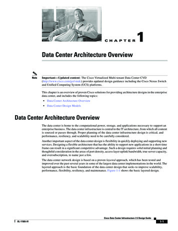
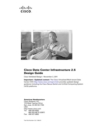
C H A P T E R1Data Center Architecture OverviewNoteImportant—Updated content: The Cisco Virtualized Multi-tenant Data Center CVD(http://www.cisco.com/go/vmdc) provides updated design guidance including the Cisco Nexus Switchand Unified Computing System (UCS) platforms.This chapter is an overview of proven Cisco solutions for providing architecture designs in the enterprisedata center, and includes the following topics: Data Center Architecture Overview Data Center Design ModelsData Center Architecture OverviewThe data center is home to the computational power, storage, and applications necessary to support anenterprise business. The data center infrastructure is central to the IT architecture, from which all contentis sourced or passes through. Proper planning of the data center infrastructure design is critical, andperformance, resiliency, and scalability need to be carefully considered.Another important aspect of the data center design is flexibility in quickly deploying and supporting newservices. Designing a flexible architecture that has the ability to support new applications in a short timeframe can result in a significant competitive advantage. Such a design requires solid initial planning andthoughtful consideration in the areas of port density, access layer uplink bandwidth, true server capacity,and oversubscription, to name just a few.The data center network design is based on a proven layered approach, which has been tested andimproved over the past several years in some of the largest data center implementations in the world. Thelayered approach is the basic foundation of the data center design that seeks to improve scalability,performance, flexibility, resiliency, and maintenance. Figure 1-1 shows the basic layered design.Cisco Data Center Infrastructure 2.5 Design GuideOL-11565-011-1
Chapter 1Data Center Architecture OverviewData Center Architecture OverviewFigure 1-1Basic Layered DesignCampus CoreCoreAggregation10 Gigabit EthernetGigabit Ethernet orEtherchannelBackup143340AccessThe layers of the data center design are the core, aggregation, and access layers. These layers arereferred to extensively throughout this guide and are briefly described as follows: Core layer—Provides the high-speed packet switching backplane for all flows going in and out ofthe data center. The core layer provides connectivity to multiple aggregation modules and providesa resilient Layer 3 routed fabric with no single point of failure. The core layer runs an interiorrouting protocol, such as OSPF or EIGRP, and load balances traffic between the campus core andaggregation layers using Cisco Express Forwarding-based hashing algorithms. Aggregation layer modules—Provide important functions, such as service module integration,Layer 2 domain definitions, spanning tree processing, and default gateway redundancy.Server-to-server multi-tier traffic flows through the aggregation layer and can use services, such asfirewall and server load balancing, to optimize and secure applications. The smaller icons within theaggregation layer switch in Figure 1-1 represent the integrated service modules. These modulesprovide services, such as content switching, firewall, SSL offload, intrusion detection, networkanalysis, and more. Access layer—Where the servers physically attach to the network. The server components consistof 1RU servers, blade servers with integral switches, blade servers with pass-through cabling,clustered servers, and mainframes with OSA adapters. The access layer network infrastructure consistsof modular switches, fixed configuration 1 or 2RU switches, and integral blade server switches. Switchesprovide both Layer 2 and Layer 3 topologies, fulfilling the various server broadcast domain oradministrative requirements.Cisco Data Center Infrastructure 2.5 Design Guide1-2OL-11565-01
Chapter 1Data Center Architecture OverviewData Center Design ModelsThis chapter defines the framework on which the recommended data center architecture is based andintroduces the primary data center design models: the multi-tier and server cluster models.Data Center Design ModelsThe multi-tier model is the most common design in the enterprise. It is based on the web, application,and database layered design supporting commerce and enterprise business ERP and CRM solutions. Thistype of design supports many web service architectures, such as those based on Microsoft .NET or Java2 Enterprise Edition. These web service application environments are used by ERP and CRM solutionsfrom Siebel and Oracle, to name a few. The multi-tier model relies on security and applicationoptimization services to be provided in the network.The server cluster model has grown out of the university and scientific community to emerge acrossenterprise business verticals including financial, manufacturing, and entertainment. The server clustermodel is most commonly associated with high-performance computing (HPC), parallel computing, andhigh-throughput computing (HTC) environments, but can also be associated with grid/utility computing.These designs are typically based on customized, and sometimes proprietary, application architecturesthat are built to serve particular business objectives.Chapter 2, “Data Center Multi-Tier Model Design,” provides an overview of the multi-tier model, andChapter 3, “Server Cluster Designs with Ethernet,” provides an overview of the server cluster model.Later chapters of this guide address the design aspects of these models in greater detail.Multi-Tier ModelThe multi-tier data center model is dominated by HTTP-based applications in a multi-tier approach. Themulti-tier approach includes web, application, and database tiers of servers. Today, most web-basedapplications are built as multi-tier applications. The multi-tier model uses software that runs as separateprocesses on the same machine using interprocess communication (IPC), or on different machines withcommunications over the network. Typically, the following three tiers are used: Web-server Application DatabaseMulti-tier server farms built with processes running on separate machines can provide improvedresiliency and security. Resiliency is improved because a server can be taken out of service while thesame function is still provided by another server belonging to the same application tier. Security isimproved because an attacker can compromise a web server without gaining access to the application ordatabase servers. Web and application servers can coexist on a common physical server; the databasetypically remains separate.Cisco Data Center Infrastructure 2.5 Design GuideOL-11565-011-3
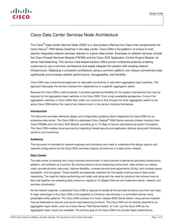
Chapter 1Data Center Architecture OverviewData Center Design ModelsResiliency is achieved by load balancing the network traffic between the tiers, and security is achievedby placing firewalls between the tiers. You can achieve segregation between the tiers by deploying aseparate infrastructure composed of aggregation and access switches, or by using VLANs (seeFigure 1-2).Physical Segregation in a Server Farm with Appliances (A) and Service Modules (B)(A)Web serversApplicationserversDatabaseservers(B)Web serversApplicationservers143341Figure 1-2DatabaseserversThe design shown in Figure 1-3 uses VLANs to segregate the server farms. The left side of theillustration (A) shows the physical topology, and the right side (B) shows the VLAN allocation acrossthe service modules, firewall, load balancer, and switch. The firewall and load balancer, which areVLAN-aware, enforce the VLAN segregation between the server farms. Note that not all of the VLANsrequire load balancing. For example, the database in the example sends traffic directly to the firewall.Cisco Data Center Infrastructure 2.5 Design Guide1-4OL-11565-01
Chapter 1Data Center Architecture OverviewData Center Design ModelsLogical Segregation in a Server Farm with VLANsABWeb nserversWeb servers143342Figure 1-3Physical segregation improves performance because each tier of servers is connected to dedicatedhardware. The advantage of using logical segregation with VLANs is the reduced complexity of theserver farm. The choice of physical segregation or logical segregation depends on your specific networkperformance requirements and traffic patterns.Business security and performance requirements can influence the security design and mechanismsused. For example, the use of wire-speed ACLs might be preferred over the use of physical firewalls.Non-intrusive security devices that provide detection and correlation, such as the Cisco Monitoring,Analysis, and Response System (MARS) combined with Route Triggered Black Holes (RTBH) andCisco Intrusion Protection System (IPS) might meet security requirements. Cisco Guard can also bedeployed as a primary defense against distributed denial of service (DDoS) attacks. For more details onsecurity design in the data center, refer to Server Farm Security in the Business Ready Data CenterArchitecture v2.1 at the following rprise/Data Center/ServerFarmSec 2.1/ServSecDC.html.Server Cluster ModelIn the modern data center environment, clusters of servers are used for many purposes, including highavailability, load balancing, and increased computational power. This guide focuses on the highperformance form of clusters, which includes many forms. All clusters have the common goal of combiningmultiple CPUs to appear as a unified high performance system using special software and high-speednetwork interconnects. Server clusters have historically been associated with university research,scientific laboratories, and military research for unique applications, such as the following: Meteorology (weather simulation) Seismology (seismic analysis) Military research (weapons, warfare)Cisco Data Center Infrastructure 2.5 Design GuideOL-11565-011-5
Chapter 1Data Center Architecture OverviewData Center Design ModelsServer clusters are now in the enterprise because the benefits of clustering technology are now beingapplied to a broader range of applications. The following applications in the enterprise are driving thisrequirement: Financial trending analysis—Real-time bond price analysis and historical trending Film animation—Rendering of artist multi-gigabyte files Manufacturing—Automotive design modeling and aerodynamics Search engines—Quick parallel lookup plus content insertionIn the enterprise, developers are increasingly requesting higher bandwidth and lower latency for agrowing number of applications. The time-to-market implications related to these applications can resultin a tremendous competitive advantage. For example, the cluster performance can directly affect gettinga film to market for the holiday season or providing financial management customers with historicaltrending information during a market shift.HPC Cluster Types and InterconnectsIn the high performance computing landscape, various HPC cluster types exist and various interconnecttechnologies are used. The top 500 supercomputer list at www.top500.org provides a fairlycomprehensive view of this landscape. The majority of interconnect technologies used today are basedon Fast Ethernet and Gigabit Ethernet, but a growing number of specialty interconnects exist, forexample including Infiniband and Myrinet. Specialty interconnects such as Infiniband have very lowlatency and high bandwidth switching characteristics when compared to traditional Ethernet, andleverage built-in support for Remote Direct Memory Access (RDMA). 10GE NICs have also recentlyemerged that introduce TCP/IP offload engines that provide similar performance to Infiniband.The Cisco SFS line of Infiniband switches and Host Channel Adapters (HCAs) provide highperformance computing solutions that meet the highest demands. For more information on Infinibandand High Performance Computing, refer to the following ex.html.The remainder of this chapter and the information in Chapter 3, “Server Cluster Designs with Ethernet”focus on large cluster designs that use Ethernet as the interconnect technology.Although high performance clusters (HPCs) come in various types and sizes, the following categorizesthree main types that exist in the enterprise environment: HPC type 1—Parallel message passing (also known as tightly coupled)– Applications run on all compute nodes simultaneously in parallel.– A master node determines input processing for each compute node.– Can be a large or small cluster, broken down into hives (for example, 1000 servers over 20 hives)with IPC communication between compute nodes/hives. HPC type 2—Distributed I/O processing (for example, search engines)– The client request is balanced across master nodes, then sprayed to compute nodes for parallelprocessing (typically unicast at present, with a move towards multicast).– This type obtains the quickest response, applies content insertion (advertising), and sends to theclient.Cisco Data Center Infrastructure 2.5 Design Guide1-6OL-11565-01
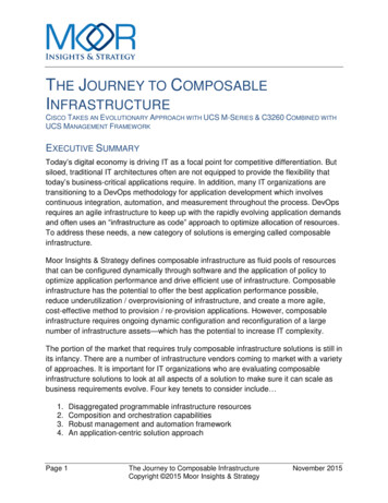
Chapter 1Data Center Architecture OverviewData Center Design ModelsHPC Type 3—Parallel file processing (also known as loosely coupled) – The source data file is divided up and distributed across the compute pool for manipulation inparallel. Processed components are rejoined after completion and written to storage.– Middleware controls the job management process (for example, platform linear file system[LFS]).The traditional high performance computing cluster that emerged out of the university and militaryenvironments was based on the type 1 cluster. The new enterprise HPC applications are more alignedwith HPC types 2 and 3, supporting the entertainment, financial, and a growing number of other verticalindustries.Figure 1-4 shows the current server cluster landscape.Server Cluster LandscapeHPC1 –Parallel Message PassingHPC2 –Distributed I/OHPC3 –Parallel File ProcessingDB –Data Base ClusterAPP –Application ClusterHA –High Availability ClusterLB –Load Balancing ClusterSC –Stretched Clustering HPC1HPC3Bandwidth RequirementsHPC2DBAppLBSCHAHPC Today:Mainly consists ofcornercase or verycustom implementations.InfinibandEthernetLatency Requirements 149000Figure 1-4The following section provides a general overview of the server cluster components and their purpose, whichhelps in understanding the design objectives described in Chapter 3, “Server Cluster Designs withEthernet.”Cisco Data Center Infrastructure 2.5 Design GuideOL-11565-011-7
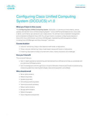
Chapter 1Data Center Architecture OverviewData Center Design ModelsFigure 1-5 shows a logical view of a server cluster.Figure 1-5Logical View of a Server ClusterPublicInterface(front end)MasterNode(s)(back end)NASPrivateInterfaceCommon FSmay beconnected viaEthernet or SANComputerNodesFC SAN(or iSCSI)143343Storage PathLogical OverviewThe components of the server cluster are as follows: Front end—These interfaces are used for external access to the cluster, which can be accessed byapplication servers or users that are submitting jobs or retrieving job results from the cluster. Anexample is an artist who is submitting a file for rendering or retrieving an already rendered result.This is typically an Ethernet IP interface connected into the access layer of the existing server farminfrastructure. Master nodes (also known as head node)—The master nodes are responsible for managing thecompute nodes in the cluster and optimizing the overall compute capacity. Usually, the master nodeis the only node that communicates with the outside world. Clustering middleware running on themaster nodes provides the tools for resource management, job scheduling, and node state monitoringof the computer nodes in the cluster. Master nodes are typically deployed in a redundant fashion andare usually a higher performing server than the compute nodes. Back-end high-speed fabric—This high-speed fabric is the primary medium for master node tocompute node and inter-compute node communications. Typical requirements include low latencyand high bandwidth and can also include jumbo frame and 10 GigE support. Gigabit Ethernet is themost popular fabric technology in use today for server cluster implementations, but othertechnologies show promise, particularly Infiniband.Cisco Data Center Infrastructure 2.5 Design Guide1-8OL-11565-01
Chapter 1Data Center Architecture OverviewData Center Design Models Compute nodes—The compute node runs an optimized or full OS kernel and is primarilyresponsible for CPU-intense operations such as number crunching, rendering, compiling, or otherfile manipulation. Storage path—The storage path can use Ethernet or Fibre Channel interfaces. Fibre Channelinterfaces consist of 1/2/4G interfaces and usually connect into a SAN switch such as a Cisco MDSplatform. The back-end high-speed fabric and storage path can also be a common transport mediumwhen IP over Ethernet is used to access storage. Typically, this is for NFS or iSCSI protocols to aNAS or SAN gateway, such as the IPS module on a Cisco MDS platform. Common file system—The server cluster uses a common parallel file system that allows highperformance access to all compute nodes. The file system types vary by operating system (forexample, PVFS or Lustre).Physical OverviewServer cluster designs can vary significantly from one to another, but certain items are common, such asthe following: Commodity off the Shelf (CotS) server hardware—The majority of server cluster implementations arebased on 1RU Intel- or AMD-based servers with single/dual processors. The spiraling cost of thesehigh performing 32/64-bit low density servers has contributed to the recent enterprise adoption ofcluster technology. GigE or 10 GigE NIC cards—The applications in a server cluster can be bandwidth intensive andhave the capability to burst at a high rate when necessary. The PCI-X or PCI-Express NIC cardsprovide a high-speed transfer bus speed and use large amounts of memory. TCP/IP offload andRDMA technologies are also used to increase performance while reducing CPU utilization. Low latency hardware—Usually a primary concern of developers is related to the message-passinginterface delay affecting the overall cluster/application performance. This is not always the casebecause some clusters are more focused on high throughput, and latency does not significantlyimpact the applications. The Cisco Catalyst 6500 with distributed forwarding and the Catalyst4948-10G provide consistent latency values necessary for server cluster environments. Non-blocking or low-over-subscribed switch fabric—Many HPC applications arebandwidth-intensive with large quantities of data transfer and interprocess communications betweencompute nodes. GE attached server oversubscription ratios of 2.5:1 (500 Mbps) up to 8:1(125 Mbps) arecommon in large server cluster designs. Mesh/partial mesh connectivity—Server cluster designs usually require a mesh or partial meshfabric to permit communication between all nodes in the cluster. This mesh fabric is used to sharestate, data, and other information between master-to-compute and compute-to-compute servers inthe cluster. Jumbo frame support—Many HPC applications use large frame sizes that exceed the 1500 byteEthernet standard. The ability to send large frames (called jumbos) that are up to 9K in size, providesadvantages in the areas of server CPU overhead, transmission overhead, and file transfer time.Cisco Data Center Infrastructure 2.5 Design GuideOL-11565-011-9
Chapter 1Data Center Architecture OverviewData Center Design ModelsFigure 1-6 takes the logical cluster view and places it in a physical topology that focuses on addressingthe preceding items.Figure 1-6Physical View of a Server Cluster Model Using ECMPBack End High Speed Fabric4-wayECMPCoreAccessMasterNodesFront End143344Computer NodesComputer NodesThe recommended server cluster design leverages the following technical aspects or features: Equal cost multi-path—ECMP support for IP permits a highly effective load distribution of trafficacross multiple uplinks between servers across the access layer. Although Figure 1-6 demonstratesa four-way ECMP design, this can scale to eight-way by adding additional paths. Distributed forwarding—By using distributed forwarding cards on interface modules, the designtakes advantage of improved switching performance and lower latency. L3 plus L4 hashing algorithms—Distributed Cisco Express Forwarding-based load balancingpermits ECMP hashing algorithms based on Layer 3 IP source-destination plus Layer 4source-destination port, allowing a highly granular level of load distribution. Scalable server density—The ability to add access layer switches in a modular fashion permits acluster to start out small and easily increase as required. Scalable fabric bandwidth—ECMP permits additional links to be added between the core and accesslayer as required, providing a flexible method of adjusting oversubscription and bandwidth perserver.In the preceding design, master nodes are distributed across multiple access layer switches to provideredundancy as well as to distribute load.Further details on multiple server cluster topologies, hardware recommendations, and oversubscriptioncalculations are covered in Chapter 3, “Server Cluster Designs with Ethernet.”Cisco Data Center Infrastructure 2.5 Design Guide1-10OL-11565-01
C H A P T E R2Data Center Multi-Tier Model DesignThis chapter provides details about the multi-tier design that Cisco recommends for data centers. Themulti-tier design model supports many web service architectures, including those based on Microsoft.NET and Java 2 Enterprise Edition. These web service application environments are used for commonERP solutions, such as those from PeopleSoft, Oracle, SAP, BAAN, and JD Edwards; and CRMsolutions from vendors such as Siebel and Oracle.The multi-tier model relies on a multi-layer network architecture consisting of core, aggregation, andaccess layers, as shown in Figure 2-1. This chapter describes the hardware and design recommendationsfor each of these layers in greater detail. The following major topics are included:Note Data Center Multi-Tier Design Ove
Nov 17, 2005 · Contents iv Cisco Data Center Infrastructure 2.5 Design Guide OL-11565-01 Recommended Platforms and Modules 2-20 Performance Implications 2-21 Traffic Flow through the Service Layer 2-22 Resiliency 2-23 CHAPTER 3 Server Cluster Designs with Ethernet 3-1 Technical Objectives 3-2 Distributed Forwarding and Latency 3-2 Catalyst 6500 System