Transcription
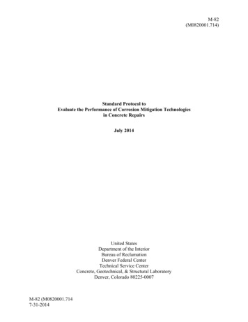
Design Data 1Highway Live Loads on Concrete PipeForewordThick, high-strength pavements designed for heavytruck traffic substantially reduce the pressure transmittedthrough a wheel to the subgrade and, consequently, tothe underlying concrete pipe. The pressure reduction isso great that generally the live load can be neglected.In 1926, Westergaard presented a paper summarizingthe results of an extensive study of the effects of loadingconditions, subgrade support, and boundary conditionson concrete pavements(1). These results formed thebasis by which Westergaard developed a method tocalculate the stresses in concrete slabs. Based upon thework of Westergaard and others, the Portland CementAssociation, (PCA), developed a method to determinethe vertical pressure on buried pipe due to wheel loadsapplied to concrete pavements(2). The PCA method ispresented in the American Concrete Pipe Association,ACPA, “Concrete Pipe Handbook” (3) and “Concrete PipeDesign Manual”(4).Intermediate and thin thicknesses of asphalt orflexible pavements do not reduce the pressure transmittedfrom a wheel to the pavement subgrade to any significantdegree. For these pavements, there is no generallyaccepted theory for estimating load distribution effects,and, therefore, these pavements should be consideredas unsurfaced roadways.Design of Highway Loads in the US often follows theAmerican Association of State Highway and TransportationOfficials, AASHTO, critieria. The AASHTO LRFD BridgeDesign Specifications specifies the applicable highwayloads and their distribution through the soil.This Design Data addresses the method ofdetermining the live load pressure transmitted throughunsurfaced roadways to circular, elliptical and archconcrete pipe in accordance with the criteria of theAASHTO LRFD Bridge Design Specifications .IntroductionTo determine the required supporting strength ofconcrete pipe installed under intermediate and thinthicknesses of asphalt or flexible pavements, or relativelyshallow earth cover, it is necessary to evaluate the effectof live loads, such as highway truck loads, in additionto dead loads imposed by the soil and surcharge loads.Live LoadsIf a rigid pavement or a thick flexible pavementdesigned for heavy duty traffic is provided with a sufficientbuffer between the pipe and pavement, then the live loadtransmitted through the pavement to the buried concretepipe is usually negligible at any depth. If any culvertor sewer pipe is within the heavy duty traffic highwayright-of-way, but not under the pavement structure, thensuch pipe should be analyzed for the effect of live loadtransmission from an unsurfaced roadway, because ofthe possibility of trucks leaving the pavement.Dead LoadsVarious methods for analyzing soil dead loads, whichhave been developed over the years, are presented in theACPA “Concrete Pipe Technology Handbook”(7).Surcharge LoadsA common type of surcharge load is additional soilfill placed after the pipe has been installed for a periodof time. If the surcharge load is a building or othersurface load, the resultant uniformly distributed loadcan be converted to an equivalent height of fill, and thenevaluated as an additional soil load. When concrete pipehas been installed underground, the soil-structure systemwill continually show an increase in load capacity. Dataon concrete pipe, which have been removed from serviceand tested, indicate an increase in concrete strengthand an increase in load carrying capacity of 10 to 40percent. Settlement and consolidation will improve thesoil structure surrounding the pipe, which also improvesload carrying capacity.Live LoadsThe AASHTO design loads commonly used in thepast were the HS 20 with a 32,000 pound axle load inthe Normal Truck Configuration, and a 24,000 poundaxle load in the Alternate Load Configuration (Figure 2).The average pressure intensity caused by a wheel loadis calculated by Equation 3.The AASHTO LRFD design loads are the HS 20with a 32,000 pound axle load in the Normal TruckConfiguration, and a 25,000 pound axle load in theAlternate Load Configuration (Figure 2).American Concrete Pipe Association www.concrete-pipe.org info@concrete-pipe.org 2009 American Concrete Pipe Association, all rights reserved.1DD 1 (07/09)
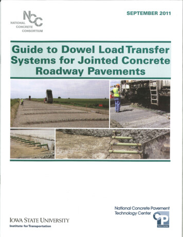
The HS 20, 32,000 pound and the Alternate Truck25,000 pound design axle are carried on dual wheels(Figure 1). The contact area of the dual wheels with theground is assumed to be a rectangle (Figure 1), withdimensions presented in Table 1.Figure 2 AASHTO Wheel Loads and WheelSpacingsHS 20 LoadHS 20 Load4000 lb.4000 lb.4000 lb.4000 lb.Figure 1 AASHTO Wheel Load SurfaceContact Area (Foot Print)16000 lb. HS 20 Load12500 lb. LRFD Alternate Load14 ft.6 ft.16000 lb.0.83 ft.(10 in.) b16000 lb.14 ft.6 ft.16000 lb.16000 lb.LRFD Alternate Loada14 ft. 12500 lb.to30 ft.1.67 ft.(20 in.)12500 lb.4 ft.Table 1 LRFD Wheel Surface Contact Areaa(width), ft(in.)b(length, ft(in.)1.67(20)0.83(10)IMPACT FACTORSThe AASHTO LRFD Standard applies a dynamicload allowance to account for the truck load being nonstatic. The dynamic load allowance, IM, is determinedby Equation 1:IM 33(1.0 - 0.125H)10016000 lb.16000 lb.12500 lb.12500 lb.HS 20 & LRFD Alternate Loads[1]where: H height of earth cover over the top of thepipe, ft.LOAD DISTRIBUTIONThe surface load is assumed to be uniformly spreadon any horizontal subsoil plane. The spread load areais developed by increasing the length and width of thewheel contact area for a load configuration as illustratedin Figure 3 for a dual wheel; in Figure 4 for dual wheels oftwo trucks in passing mode; and in Figure 5 for two dualwheels of two Alternate Load configurations in passingmode. On a horizontal soil plane, the dimensionalincreases to the wheel contact area are based on height6 ft.4 ft.Table 2 LRFD Wheel Contact AreaDimensional Increase FactorSoil TypeDimensional Increase FactorLRFD select granular1.15HLRFD any other soil1.00HAmerican Concrete Pipe Association www.concrete-pipe.org info@concrete-pipe.org 2009 American Concrete Pipe Association, all rights reserved.6 ft.2DD 1 (07/09)
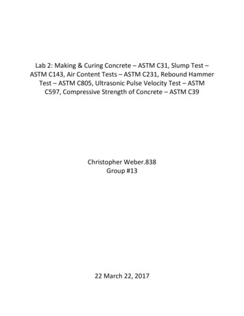
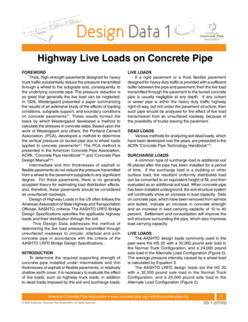
of earth cover over the top of the pipe as presented inTable 2 for two types of soil.As indicated by Figures 3, 4 and 5, the spread load areasfrom adjacent wheels will overlap as the height of earthcover over the top of the pipe increases.Live load will also dissipate through the concrete pipeitself resulting in an effective length that resists this loadas demonstrated in Figure 7. The effective supportinglength of pipe is:[2]Le L 1.75(3/4Ro)where: RO outside vertical rise of pipe, feetThe governing wheel load configuration is thusFigure 3 Spread Load Area - Single Dual WheelaDirectioDESIGN METHODThe design method encompasses 4 steps.bnof Travel1.Wheel Load AreaSpread Load AreaH ft.adSpreSpreaa combination of the overlap in live load pressuresdistributed through the soil, as well as any instance wherethe effective lengths from adjacent tires overlap within thepipe itself as shown in Figure 8. These conditionshave been summarized in Table 3.At shallow depths, the maximum pressure will bedeveloped by an HS 20 dual wheel, since at 16,000pounds it applies a greater load than the 12,500 poundAlternate Load (Figures 2 and 3). At intermediate depths,the maximum pressure will be developed by the wheelsof two HS 20 trucks in the passing mode, since at 16,000pounds each, the two wheels apply a greater load thanthe 12,500 pounds of an Alternate Load wheel (Figures 2and 4). At greater depths, the maximum pressure will bedeveloped by wheels of two Alternate Load configurationtrucks in the passing mode, since at 12,500 pounds each,the four wheels apply the greatest load (50,000 pounds)(Figures 2 and 5).adbObtain the following project data:Pipe shape, size and wall thickness.Height of cover over the concrete pipe, and type ofearth fill.LRFD or other criteria.2. Calculate the average pressure intensity of the wheelloads on the soil plane on the outside top of thepipe.3. Calculate the total live load acting on the pipe.4. Calculate the total live load acting on the pipe inpounds per linear foot.Table 3 LRFD Critical Wheel Loads and Spread Dimensions at the Top of the PipeVehicle Traveling Perpendicular to PipeH, ftP, lbsSpread a, ftSpread b, ftFigureLive Load Distribution H 1.15DO 2.05of 1.15 x H for Select2.05 - 1.15DO H 5.5Granular Fill5.5 H16,000a 1.15Hb 1.15H332,000a 4 1.15Hb 1.15H450,000a 4 1.15Hb 4 1.15H5Live Load Distribution H 1.30DO 2.30of 1.0 x H for Other2.30 - 1.30 DO H 6.3Soils6.3 H16,000a 1.00Hb 1.00H332,000a 4 1.00Hb 1.00H450,000a 4 1.00Hb 4 1.00H5Vehicle Traveling Parallel to PipeLive Load Distribution H 2.03of 1.15 x H for Select2.03 H 5.5Granular Fill5.5 H16,000a 1.15Hb 1.15H332,000a 4 1.15Hb 1.15H450,000a 4 1.15Hb 4 1.15H5Live Load Distribution H 2.33of 1.0 x H for Other2.33 H 6.3Soils6.3 H16,000a 1.00Hb 1.00H332,000a 4 1.00Hb 1.00H450,000a 4 1.00Hb 4 1.00H5American Concrete Pipe Association www.concrete-pipe.org info@concrete-pipe.org 2009 American Concrete Pipe Association, all rights reserved.3DD 1 (07/09)
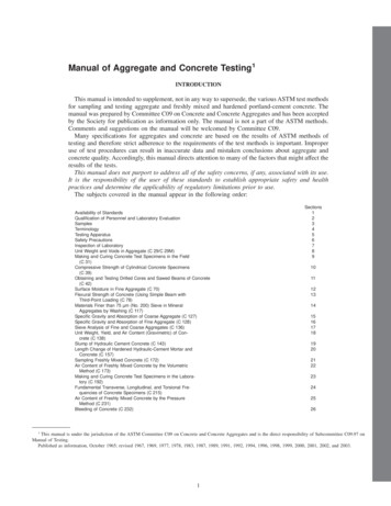
Figure 4 Spread Load Area - Two Single Dual Wheels of Trucks in Passing ModeWheel Load Areas4.0WheelLoad Areasft.7Direc1.6tioanob .83ft.ft.fTravelH ft.adreSpSpaDistributed Load AreareadbFigure 5 Spread Load Area - Two Single Dual Wheels of Two Alternate Loads in Passing ModeWheel Load Areasctia4.0aft.4.0 DireWheelLoad Areasbonofft.TrabvelH ft.daapreSpSreadbDistributed Load AreaAmerican Concrete Pipe Association www.concrete-pipe.org info@concrete-pipe.org 2009 American Concrete Pipe Association, all rights reserved.4DD 1 (07/09)
Average Pressure IntensityThe wheel load average pressure intensity on thesubsoil plane at the outside top of the concrete pipe is:w P(1 IM)A[3]where: w wheel load average pressure intensity,pounds per square footP total live wheel load applied at the surface,poundsA spread wheel load area at the outside topof the pipe, square feetIM dynamic load allowanceFrom the appropriate Table 3, or 4, select the criticalwheel load and spread dimensions for the height of earthcover over the outside top of the pipe, H. The spread liveload area is equal to Spread a times Spread b. Select theappropriate dynamic load allowance, using Equation 1.Total Live LoadA designer is concerned with the maximum possibleloads, which occur when the distributed load area iscentered over the buried pipe. Figure 6 illustrates thedimensions of the spread load area, A, related to whetherthe truck travel is transverse or parallel to the centerlineof the pipe. The total live load acting on the pipe is :WT wLSLFigure 6 Spread Load Area Dimensions vsDirection of TruckSpread bDirection of TravelSpread bDirection of TravelSpread aPipePipeCenterlineSpread aProject DataPipe shape and internal dimensions are shown onthe project plans. Complete information on dimensionaldetails are included in ASTM Specification C 14 fornonreinforced circular concrete pipe(8), C 76 for reinforcedconcrete circular pipe(9), C 506 for reinforced concrete archpipe(10) and C 507 for reinforced concrete elliptical pipe(11).Internal size, wall thickness and outside dimensionsare presented in Tables 6, 7 and 8 for circular, arch andelliptical pipe respectively.The minimum earth cover over the concrete pipecan be obtained from the project plans. The type of fillmaterial required under, around and over the concretepipe will be noted on the project plans or detailed in thecontract documents.A decision regarding whether the AASHTO LRFD orother criteria will be used should be obtained from theproject authority.L dimension of A parallel to the longitudinalaxis of pipe, feetFor vehicles traveling perpendicular tothe pipe, L spread aFor vehicles traveling parallel to the pipe,L spread bSL outside horizontal span of pipe, DO, orspread wheel load area, A, transverse tothe longitudinal axis of pipe, whichever isless, feetTotal Live Load in Pounds per Linear FootThe total live load in pounds per linear foot, WL, iscalculated by dividing the Total Live Load, WT, by theEffective Supporting Length, Le (See Figure 7), of thepipe:WL WTLe[5]where: WL live load on top of pipe,pounds per linear footLe effective supporting length ofpipe (see Equation 2 and Figure 7), feet[4]where: WT total live load, poundsw wheel load average pressure intensity,pounds per square foor (at the top of thepipe)American Concrete Pipe Association www.concrete-pipe.org info@concrete-pipe.org 2009 American Concrete Pipe Association, all rights reserved.5DD 1 (07/09)
Figure 7 Effective Supporting Length of PipeWheel Surface Contact AreaLH3R04R0Pipe CenterlineLe L 1.75(3/4Bc)Figure 8 Load Spread Through Soil and Pipe4 ftH3/4 ROROEXAMPLESFour Example calculations are presented on the following pages to illustrate the four steps of the Design Method,and the effect of varying the depth of fill and the type of fill. The live loads per linear foot calculated in the fourExamples are summarized in Table 4. 5Table 4 Summary of LRFD Live Loads Calculated in ExamplesExampleD, inLoadSoil FillH, ftP, lbsLive Load, plf130PerpendicularSelect Granular232,0003,272230ParallelSelect Granular216,0002,162330PerpendicularOther Soil232,0003,407430PerpendicularSelect Granular650,000855American Concrete Pipe Association www.concrete-pipe.org info@concrete-pipe.org 2009 American Concrete Pipe Association, all rights reserved.6DD 1 (07/09)
EXAMPLE 1Given: A 30-inch diameter, B wall, concrete pipe is tobe installed as a storm drain under a flexiblepavement and subjected to AASHTO highwayloadings that run perpendicular to the pipe. Thepipe will be installed in a trench with a minimumof 2 feet of cover over the top of the pipe. TheAASHTO LRFD Criteria will be used with SelectGranular Soil.Find: The maximum live load on the pipe in poundsper linear foot.Solution:1. Review project data.A 30-inch diameter, B wall, circular concrete pipe hasa wall thickness of 3.5 inches, therefore the outsidediameter of the pipe, DO, and Ro are 3.08 feet. The heightof earth cover is 2 feet. Use AASHTO LRFD Criteria withSelect Granular Soil Fill.2. Calculate average pressure intensity of the live loadon the plane at the outside top of the pipe.From Table 3, the critical load, P, is 32,000 pounds fromtwo HS 20 single dual wheels in passing mode, and theSpread Area is:A (Spread a)(Spread b)A (1.67 4 1.15 x 2)(0.83 1.15 x 2)A (7.97)(3.13)A 24.9 square feetFrom Equation 1:I.M. 33(1.0 - 0.125H)/100I.M. .2475 (24.75%)From Equation 3:w P(1 IM)/Aw 32,000(1 .2475)/24.9w 1,603 lb/ft2WT 1603 x 7.97 x 3.08 39,300 pounds4. Calculate live load on pipe in pounds per linear foot.Ro 3.08 feetFrom Equation 2:Le L 1.75(3/4Ro)Le 7.97 1.75(.75x3.08) 12.01 feetWL WT/LeWL 39,300/12.01 3,272 pounds per linear footEXAMPLE 2Given: Same as Example 1, except the live load runsparallel to the pipe.Find: The maximum live load on the pipe in poundsper linear foot.Solution:1. Review project data.A 30-inch diameter, B wall, circular concrete pipe hasa wall thickness of 3.5 inches, therefore DO and RO are3.08 feet. Height of earth cover is 2 feet. Use AASHTOLRFD Criteria with Select Granular Soil Fill.2. Calculate average pressure intensity of the live loadon the plane at the outside top of the pipe.From Table 3, the critical load, P, is 16,000 pounds froman HS 20 single dual wheel, and the Spread Area is:A (Spread a)(Spread b)A (1.67 1.15 x 2)(0.83 1.15 x 2)A (3.97)(3.13)A 12.4 square feetFrom Equation 1:I.M. 33(1.0 - 0.125H)/100I.M. .2475(24.75%)3. Calculate total live load acting on the pipe.From Equation 4:WT wLSLFrom Equation 3:w P(1 IM)/Aw 16,000(1 .2475)/12.4w 1,610 lb/ft2Since the truck travels transverse to pipe centerline.3. Calculate total live load acting on the pipe.L Spread a 7.97 feetSpread b 3.13 feetDO 3.08 feet, which is less than Spread b, thereforeSL 3.08 feetFrom Equation 4:WT wLSLSince the truck travels parallel to pipe centerline.American Concrete Pipe Association www.concrete-pipe.org info@concrete-pipe.org 2009 American Concrete Pipe Association, all rights reserved.7DD 1 (07/09)
Spread a 3.97 feetL Spread b 3.13 feetBC 3.08 feet, which is less than Spread a, thereforeSL 3.08 feet3. Calculate total live load acting on the pipe.WT (1603)3.08 x 3.13 15,500 poundsSince the truck travels transverse to pipe centerline.4. Calculate live load on pipe in pounds per linear foot.L Spread a 7.67 feetSpread b 2.83 feetDO 3.08 feet, which is greater than Spread b,thereforeSL 2.83 feetRo 3.08 feetLe L 1.75(3/4Ro)Le 3.13 1.75(.75x3.08) 7.17 feetWL WT/LeWL 15,500/7.17 2,162 pounds per linear footEXAMPLE 3Given: Same as Example 1, except use AASHTO LRFDCriteria with Other Soils Fill.Find:The maximum live load on the pipe in poundsper linear foot.Solution:1. Review project data.A wall B 30-inch diameter circular concrete pipe hasa wall thickness of 3.5 inches, therefore the outsidediameter of the pipe, DO, and Ro are 3.08 feet. Height ofearth cover is 2 feet. Use AASHTO LRFD Criteria withOther Soils Fill.2. Calculate average pressure intensity on the plane atthe top of the pipe.From Equation 4:WT wLSLWT 1,839 x 7.67 x 2.83 39,900 pounds4. Calculate live load on pipe in pounds per linear foot.Ro 3.08 feetFrom Equation 2:Le L 1.75(3/4Ro)Le 7.67 1.75(.75 x 3.08) 11.71 feetWL WT/LeWL 39,900/11.71 3,407 pounds per linear footEXAMPLE 4Given: Same as Example 1, except minimum depth offill is 6 feet.Find:The maximum live load on the pipe in poundsper linear foot.Solution:1. Review project data.From Table 3, the critical load, P, is 32,000 pounds fromtwo HS 20 single dual wheels in passing mode, and theSpread Area is:A (Spread a)(Spread b)A (1.67 4 1.00 x 2)(0.83 1.00 x 2)A (7.67)(2.83)A 21.71 square feetFrom Equation 1:I.M. 33(1.0 - 0.125H)/100I.M. .2475From Equation 3:w P(I IM)/Aw 32,000(1 .2475)/21.71w 1,839 lb/ft2A wall B 30-inch diameter circular concrete pipe has a wallthickness of 3.5 inches, therefore the outside diameterof the pipe, DO, and Ro are 3.08 feet. Height of earthcover is 6 feet. Use AASHTO LRFD Criteria with SelectGranular Soil Fill.2. Calculate average pressure intensity at the outsidetop of the pipe.From Table 3, the critical load, P, is 50,000 poundsfrom two single dual wheels of two Alternate LoadConfigurations in the passing mode, and the SpreadArea is:A (Spread a)(Spread b)A (1.67 4 1.15 x 6)(0.83 4 1.15 x 6)American Concrete Pipe Association www.concrete-pipe.org info@concrete-pipe.org 2009 American Concrete Pipe Association, all rights reserved.8DD 1 (07/09)
A (12.57)(11.73)A 147.45 square feetFrom Equation 1:I.M. 33(1-0.125H)/100I.M. 0.0825L Spread a 12.57 feetSpread b 11.73 feetDO 3.08 feet, which is less than Spread b, thereforeSL 3.08 feetWT 367 x 12.57 x 3.08 14,200 poundsFrom Equation 3:w P(1 I.M.)/A 50,000(1 0.0825)/147.45w 367 lb/ft24. Calculate live load on pipe in pounds per linear foot.Ro 3.08 feet3. Calculate total live load acting on the pipe.WT wLSLSince the truck travels transverse to pipe centerline.From Equation 2:Le L 1.75(3/4Ro)Le 12.57 1.75(0.75x3.08) 16.6 feetWL WT/LeWL 14,200/16.6 855 pounds per linear footTable 6 Dimensions ofCircular Concrete PipeWall A Wall B Wall CInternal Minimum Minimum MinimumDiameter, Wall Wall Wallinches Thickness, 6-1/416-3/4Table 7 Dimensions of EllipticalConcrete PipeEquivalent Minor Major Minimum WallRound Size, Axis, Axis Thickness,inches inches inchesinchesTable 7 Dimensions of ArchConcrete PipeMinimumEquivalent Minimum Minimum WallRound Size, Rise, Span,Thickness,inchesinches 38434853586368727782879297106116American Concrete Pipe Association www.concrete-pipe.org info@concrete-pipe.org 2009 American Concrete Pipe Association, all rights D 1 (07/09)
References1.Westergaard, H.M., “Stresses in ConcretePavements Computed by Theoretical Analysis”,Public Roads, April, 1926.2. “Vertical Pressure on Culverts Under Wheel Loadson Concrete Pavement Slabs”, Portland CementAssociation, 1944.3. “Concrete Pipe Handbook”, American ConcretePipe Association, 1998.4. “Concrete Pipe Design Manual”, AmericanConcrete Pipe Association, 2000.5. “Standard Specifications for Highway Bridges”,American Association for State Highway andTransportation Officials.6. “LRFD Bridge Design Specifications”, AmericanAssociation for State Highway and TransportationOfficials.7.“Concrete Pipe Technology Handbook”, AmericanConcrete Pipe Association, 1993.8. ASTM Standard C 14, “Specification for ConcreteSewer, Storm Drain, and Culvert Pipe”, AmericanSociety for Testing and Materials.9. ASTM Standard C 76, “Specification for ReinforcedConcrete Culvert, Storm Drain, and Sewer Pipe”,American Society for Testing and Materials.10. ASTM Standard C 506, “Specification forReinforced Concrete Arch Culvert, Storm Drain,and Sewer Pipe”, American Society for Testing andMaterials.11. ASTM Standard C 507, “Specification forReinforced Concrete Elliptical Culvert, StormDrain, and Sewer Pipe”, American Society forTesting and Materials.American Concrete Pipe Association www.concrete-pipe.org info@concrete-pipe.org 2009 American Concrete Pipe Association, all rights reserved.Technical data herein is considered reliable, but no guarantee is made or liability assumed.10DD 1 (07/09)
ACPA, “Concrete Pipe Handbook” (3) and “Concrete Pipe Design Manual”(4). Intermediate and thin thicknesses of asphalt or flexible pavements do not reduce the pressure transmitted from a wheel to the pavement subgrade to any significant degree. For these pavements, there is no generally accepted the