Transcription
Mallory HyFire Pro Ignition ControlPN 695Parts Included:1 - Ignition1 - Harness, Mag Pickup1 - Screwdriver1 - Parts Bag, ASY 289284 - Vibration MountsWARNING: During installation, disconnect the battery cables. When disconnecting the battery alwaysremove the Negative cable first and install it last.Note: Solid Core spark plug wires cannot be used with an Mallory HyFire Pro Ignition.Note: Do not use digital or dial back timing lights.OPERATION AND FEATURESDIGITAL OPERATIONThe Mallory HyFire Pro uses a high speed RISC microcontroller to control the ignition's output whileconstantly analyzing the various inputs such as supply voltage, trigger signals and rpm. The highspeed controller can make extremely quick compensations to the output voltage, multiple spark series, timing and rpm limits while maintaining accurate timing signals to within 1 and 1% of the rpmlimits. The circuits and controller of the Mallory HyFire Pro have been thoroughly filtered to createprotection against Electro Magnetic Interference (EMI).CAPACITIVE DISCHARGEThe Mallory HyFire Pro features a capacitive discharge ignition design. The majority of stock ignitionsystems are inductive ignitions. In an inductive ignition, the coil must store and step up the voltageto maximum strength in between each firing. At higher rpm, since there is less time to charge the coilto full capacity, the voltage falls short of reaching maximum energy which results in a loss of poweror top end miss.The Mallory HyFire Pro features a capacitor which is quickly charged with 520 - 535 volts and storesit until the ignition is triggered. With the CD design, the voltage sent to the coil is always at full powereven at high rpm.MULTIPLE SPARKSThe Mallory HyFire Pro produces full power multiple sparks for each firing of a plug. The numberof multiple sparks that occur decreases as rpm increases, however the spark series always lasts for20 of crankshaft rotation. Above 3,000 rpm there is simply not enough “time” to fire the spark plugmore than once, so there is only one powerful spark.PROTECTIONThe Mallory HyFire Pro has a built in reverse polarity protection circuit. This will protect the ignition inthe event of wrong connections. It will also shut off for protection from a surge in power. The ignitionwill still operate once the surge or polarity is corrected.LED INDICATORThere is an LED that monitors the status of the Ignition. The LED monitors the trigger signals and willflash to warn if the supply voltage drops below 9 volts while under 3,000 rpm.
2INSTALLATION INSTRUCTIONSREV LIMITERThis Ignition features a built-in Rev Control with two different rpm limits. The circuitry provides asmooth and accurate rev limit by dropping the spark to individual cylinders. The Rev Control producesa load-free rev limit that is within 1% of the selected rpm.You can select two rev limits; one for a low limit that can be used when staging the car, and anotherlimit for top end overrev protection. Both rpm limits are adjusted in 100 rpm increments with the sealedrotary switches on the side of the ignition. Using and programming the launch limit is explained indetail on page 5.CYLINDER SELECTThe Mallory HyFire is programmed at the factory for use on 8-cylinder engines. If you are installing itto a different engine you will have to program the Ignition. This is easily achieved through the cylinderselect switch on the side of the ignition. Page 5 outlines setting the cylinder select.GENERAL INFORMATIONBATTERYA Mallory HyFire Pro Ignition Control will operate on any negative ground, 12 volt electrical systemwith a distributor. The Mallory can be used with 16 volt batteries and can withstand a momentary 24volts in case of jump starts. The Ignition will deliver full voltage with a supply of 9 - 18 volts and willoperate with a supply voltage as low as seven volts.If your application does not use an alternator, allow at least 15 amp/hour for every half hour ofoperation. The Mallory uses about .9 Amps for every 1,000 rpm. If the engine is cranked with thesame battery or other accessories such as an electric fuel or water pump are used, the amp/hourrating should be higher.COILSThe Mallory HyFire Pro Ignition can be used with most stock coils and aftermarket coils designedto replace the stock coils. The line of Mallory coils available for this Mallory HyFire Pro is PN30480 and PN 29440.TACHOMETERSThe Mallory HyFire Pro Ignition features a Gray Tach Output wire that provides a trigger signalfor tachometers, a shift light or other add-on rpm activated devices. The Tach Output wireproduces a 12 volt square wave signal with a 25 duty cycle.Some vehicles with factory tachometers may require a Tach Adapter to operate with theMallory HyFire Pro. For more information on Tachometers, see the Tachometer Section on page 7.If your GM vehicle has an in-line filter it may cause the tach to drop to zero on acceleration. Ifthis occurs, bypass the filter.SPARK PLUGS AND WIRESSpark plug wires are very important to the operation of your ignition system. A good quality, helicallywound wire and proper routing are required to get the best performance from your ignition. Helicallywound wires provide a good path for the spark to follow while keeping Electro Magnetic Interference(EMI) to a minimum. Excessive EMI, such as the amount that solid core wires produce, will interferewith the operation of the Mallory HyFire Pro. Solid Core spark plug wires cannot be used with anMallory HyFire Pro Ignition.
INSTALLATION INSTRUCTIONS3Routing: Correct routing of the plug wires is also important to performance. Wires should be routedaway from sharp edges and engine heat sources. If there are two wires that are next to each other inthe engine’s firing order, the wires should be routed away from each other to avoid inducing a sparkinto the other wire. For example, in a Chevy V8, the firing order is 1-8-4-3-6-5-7-2. The #5 and #7cylinders are next to each other in the engine and in the firing order. If the voltage from the #5 wire isinduced into #7 detonation could occur and cause engine damage.Spark Plugs: Choosing the correct spark plug design and heat range is important when trying to getthe best performance possible. Since there are so many engine combinations and manufacturers,Mallory does not recommend which plug or gap is exactly right for your application.It is recommended to follow the engine builder or manufacturer’s specification for spark plugs. Withthat, you can then experiment with the plug gap to obtain the best performance. The gap of the plugscan be opened in 0.005" increments, then tested until the best performance is obtained. Malloryjudges the plug gap by compression and components.These examples are just starting points to get you going in the right direction. Every application isdifferent and should be tested and tuned.Note: Close the spark plug gap down as compressionincreases.CompressionUp to 10.5:1:10.5:1 - 13.0:1:Above 13.0:1:Spark Plug Gap0.035" - 0.045"0.030" - 0.035"0.025" - 0.030"Welding: If you are welding on your vehicle, to avoidthe chance of damage, always disconnect both Heavy Power cables of the Mallory (You should alsodisconnect the tach ground wire too).Distributor Cap and Rotor: It is recommended to install a new distributor cap and rotor when installingthe Mallory Ignition Control. The cap should be clean inside and out especially the terminals and rotortip. On vehicles with smaller caps, it is possible for the air inside the cap to become electrically chargedcausing crossfire which can result in misfire. This can be prevented by drilling a couple vent holes inthe cap. The holes should be placed between the terminals, at rotor height and face away from theintake. If your environment demands it, place a small piece of screen over the hole to act as a filter.MOUNTINGThe Mallory can be mounted in the engine compartment as long as it is away from direct engine heatsources. It is not recommended to mount the unit in an enclosed area such as the glove box.When you find a suitable location to mount the unit, make sure the wires of the ignition reach theirconnections. Also be sure that the program dials can be accessed. Hold the Ignition in place andmark the location of the mounting holes. Use a 3/16" bit to drill holes, install the vibration mountsand mount the ignition.
4INSTALLATION INSTRUCTIONSWIRINGPower LeadsHeavy RedHeavy BlackRedOrangeThese are the two heavy 14 gauge wires and are responsible for gettingdirect battery voltage to the ignition. The Ignition is load protectedfrom reverse battery connections and will automatically shut down ifthere is over 28 volts input.This wire connects directly to the battery positive ( ) terminal or apositive battery junction such as the starter solenoid. Note: Do notconnect to the alternator.This wire connects to a good ground, either at the battery negative(-) terminal or to the engine.This wire is responsible for turning the Mallory On and Off. Connectsto a switched 12 volt source such as the ignition key or switch.This wire connects to the coil positive ( ) terminal. This is the ONLYwire that makes electrical contact with the positive coil terminal.BlackThis wire connects to the coil negative (-) terminal. This is the ONLYwire that makes electrical contact with the negative coil terminal.TriggerWiresThere are three circuits that can be used to trigger the Mallory Ignition;a Points circuit (the White wire), a Magnetic Pickup circuit (the Greenand Violet wires), and a Hall-effect wire (White/Blue). Only one circuitwill be used at a time.WhiteThis wire is used to connect to breaker points, electronic ignitionamplifier output or to the output wire of an aftermarket TimingAccessory. When this wire is used, the White/Blue wire andMagnetic Pickup connector are not used.Hall-effect Trigger. This wire connects to the trigger wire of a Halleffect pickup. When used, the White and Magnetic Pickup wiresare not used.These wires are routed together in one harness as the magnetic pickupconnector. It will also connect to aftermarket pickups. The Violet wireis positive ( ) and the Green wire is negative (-). When these wiresare used, the White or White/Blue wires are not.White/BlueVioletand his wire activates the Launch Rev Control. When 12 volts is appliedto this wire, the low rpm limit is activated. When 12 volts is removed,the rev limit returns to the high limit.Tach output wire. Connects to the tachometer trigger wire or otherrpm activated device.GENERAL WIRING INFORMATIONWire Length: All of the wires of the Mallory Ignition may be shortened as long as quality connectorsare used or soldered in place. To lengthen the wires, use one size bigger gauge wire (12 gauge forthe power leads and 16 gauge for the other wires) with the proper connections. All connections mustbe soldered and sealed.
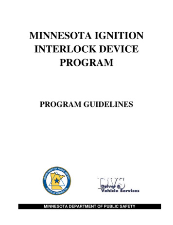
INSTALLATION INSTRUCTIONS5Grounds: A poor ground connection can cause many frustrating problems. When a wire is specifiedto go to ground, it should be connected to the battery negative terminal, engine block or chassis.There should always be a ground strap between the engine and the chassis. Always securely connectthe ground wire to a clean, paint free metal surface.Ballast Resistor: If your vehicle has a ballast resistor in-line with the coil wiring, it is recommendedto bypass it.Routing Wires: The Mallory wires should be routed away from direct heat sources such as exhaustmanifolds and headers and any sharp edges. The trigger wires should be routed separate from theother wires and spark plug wires. It is best if they are routed along a ground plane such as the blockor firewall which creates an electrical shield. The magnetic pickup wires should always be routedseparately and should be twisted together to help reduce extraneous interference.PROGRAMMINGCYLINDER SELECTCYLINDERCOUNTThe Mallory is programmed for operation on 8-cylinderengines. If installing the Ignition on a different style engine, thenumber of cylinders will need to be selected on the CylinderSelect Rotary Switch (Figure 1).64REV LIMITERThere are two adjustable rev limits that you can adjust; theMax Limit and the Launch Limit. Both limits are adjusted in100 rpm increments by turning the rotary switches on the sideof the Ignition (Figure 2). Note: The engine can be running asyou make adjustments to the rev limiter function.CYL8Figure 1 Programming the Number ofCylinders.Max Limit: This is the overrev rpm limit. The Rev Launch circuitry will begin dropping the spark tocylinders any time the rpm reaches the amount you select, except if the Launch Limit is activated (12volts applied to the Blue wire). The limit can be adjusted from 2,000 to 11,900 rpm. Setting both dialsto Zero defaults to a limit of 10,000 rpm. Setting the 1,000's dial to 1 defaults to 11,000 rpm rev limit.THIS EXAMPLESHOWS 2,500RPM.THIS EXAMPLESHOWS THEOVERREV AT6,500.THIS EXAMPLESHOWS 8-CYLINDER ENGINE (FULLCLOCKWISE).64Figure 2 Adjusting the Rev Limits.Figure 2 Rev Limiter sample setting.CYL8
6Launch Limit: This rpm limit is activatedwhen 12 volts are applied to the Bluewire. When activated, this limit overridesthe Max Limit. This limit is adjustablefrom 1,000 to 9,900 and will default to1,000 rpm if the dials are set to an rpmbelow this range. An example of wiringthe Launch Limit so it is activated withthe line-lock is shown in Figure 3.INSTALLATION INSTRUCTIONSTO 12VBLUE TO TRANS-BRAKEOR LINE-LOCK SOLENOIDPN 695Figure 3 Wiring the Launch Rev Limit.PRESTART CHECK LIST The only wires connected to the coil terminals are the Mallory Orange to coil positive and Black to coil negative.The small Red wire of the Mallory is connected to a switched 12 volt source.Confirm the cylinder select is in the proper position for your application.The Mallory power leads are connected directly to the battery positive and negative terminals.The battery is connected and fully charged if not using an alternator.The engine is equipped with at least one ground strap to the chassis.TROUBLESHOOTINGLEDThe LED on the side of the Mallory unit monitors several operating conditions. If the LED indicatesthat there is a problem with the ignition system, follow the steps through the Troubleshooting section.The LED will appear to be on steady above idle speeds when everything is functioning properly. Flashes once per second if the battery supply voltage is low when under 3,000 rpm (whilemultiple sparking). This indicates a charging problem or poor connection. It will flash approximately once per second if the battery input voltage is above 28 volts fora sustained amount of time. The LED will flash for every trigger signal from the distributor or crank trigger. You can takeadvantage of this when statically setting the timing when using the White or White/Blue wire to trigger.TACH/FUEL ADAPTERSIf your tachometer does not operate correctly or if you experience a no-run situation with your foreignvehicle you probably need a Mallory PN 29074 or Mallory PN 29078. The chart in Figure 4 lists commontachometers and if an Adapter is necessary.
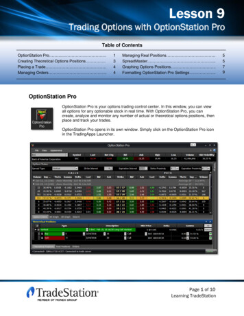
INSTALLATION INSTRUCTIONS7Tachometer Compatibility ListAFTERMARKET TACHOMETERWHITE WIRE TRIGGERMAGNETIC TRIGGER CONNECTORAUTOGAGE2907429078AUTOMETERNONENONEFORD EWART (voltage triggered)2907429078S.W. & BI TORXNONENONESUN2907429078VDONONENONEAMC (JEEP)2907429078CHRYSLER2907429078FORD (voltage triggered)2907429078GENERAL MOTORSBypass In-Line FilterBypass In-line filterIMPORTS2907429078Note: On the list above, the trigger wire on tachometers that are marked NONE may be connected to the GrayTach Output Wire on the Mallory HyFire Pro Ignition.Figure 4 Common Tachometers and Adapters.NO-RUN ON FOREIGN VEHICLESSome foreign vehicles with fuel injection systems may require an Mallory Tach/Fuel Injection Adapterto run with aMallory HyFire Ignition. This is because many of these systems use the same triggersource to operate the Mallory, the tachometer and the fuel injection. This results in a voltage signalthat is too low to accurately trigger the fuel injection. To fix this, a Mallory Tach Adapter, PN 29074,will remedy the problem on the majority of vehicles.Note: Toyotas and Ford Probes will require the MSD PN 8910-EIS Adapter.INOPERATIVE TACHOMETERSIf your tachometer fails to operate with the Mallory installed you may need an Mallory Tach Adapter.Before getting an Adapter, try connecting your tachometer trigger wire to the Gray tach wire of theMallory. This output produces a 12 volt, square wave (see page 2). If the tach still does not operate,you will need a Tach Adapter. There are two Tach Adapters:PN 29078: If you are using the Magnetic Pickup connector (Green and Violet wires) to trigger theMallory, you will need the PN 29078.PN 29074: If your tachometer was triggered from the coilnegative terminal (voltage trigger) and you are using theWhite wire to trigger the Mallory you will need the PN 29074.BALLAST RESISTORIf you have a current trigger tach (originally coil positive)and use the White wire of the Mallory, you can purchasea Chrysler Dual Ballast Resistor (used from 1973 - 1976)and wire it as shown in Figure 5.Figure 5 Wiring the Dual Ballast Resistor.EARLY GM VEHICLESATTACH DIODE TO TERMINAL "4"ENGINE RUN-ONIf your engine continues to run even when the ignitionis turned Off you are experiencing engine Run-On. Thisusually only occurs on older vehicles with an externalvoltage regulator. Because the Mallory receives powerdirectly from the battery, it does not require much current to12341A-100V DIODEFORD VEHICLESATTACH DIODE TO TERMINAL "1"SPLICE HERETOCHARGINGLIGHTFigure 6 Installing the diode to a GM or Ford Vehicle.
8INSTALLATION INSTRUCTIONSkeep the unit energized. If you are experiencing run-on, it is due to a small amount of voltage going throughthe charging lamp indicator and feeding the small Red wire even if the key is turned off.Early Ford and GM: To solve the Run-On problem, a Diode is supplied with the Mallory in the partsbag. By installing this Diode in-line of the wire that goes to the Charging indicator, the voltage is keptfrom entering the Mallory. Figure 6 shows the proper installationGM 2-WIRE ALTERNATORSfor early Ford and GM vehicles.Note: Diodes are used to allow voltage to flow only one way. Makesure the Diode is installed facing the proper direction (asshown in Figure 6).WIRE LOOMSMALLER OF THE 2-WIRESDIODEFord: Install the Diode in-line to the wire going to the “1” terminal.GM: Install the Diode in-line to the wire going to terminal #4.GM: 1973 - 1983 with Delcotron Alternators.GM: Delcotron Alternators use an internal voltage regulator. Installthe Diode in-line on the smallest wire exiting the alternator (Figure7). It is usually a Brown wire.Most other applications: Onother applications where engineRun-On is experienced, aResistor can be put in-line tothe Mallory's small Red wire(Figure 8). This resistor will keepvoltage from leaking through tothe Mallory unit.Figure 7 Installing the Diode to a1973-1983 GM Vehicle.MALLORYFigure 8 Wiring the Dual Ballast Resistor for Run-On.MISSES AND INTERMITTENT PROBLEMSExperience at the races has shown that if your engine is experiencing a miss or hesitation at higherrpm, it is usually not directly ignition. Most probable causes include faulty wiring, a coil or plug wirefailure, arcing from the cap or boot plug to ground or spark ionization inside the cap. Several itemsto inspect are: Always inspect the plug wires at the cap and at the plug for a tight connection and visually inspectfor cuts, abrasions or burns. Inspect the Primary Coil Wire connections. Because the Mallory is a Capacitive Discharge ignition andit receives a direct 12 volt source from the battery, there will not be any voltage at the Coil Positive ( )terminal even with the key turned On. During cranking or while the engine is running, very high voltagewill be present and no test equipment should be connected.WARNING: Do not touch the coil terminals during cranking or while the engine is running. Make sure that the battery is fully charged and the connections are clean and tight. If you are notrunning an alternator this is an imperative check. If the battery voltage falls below 9 volts duringa race, the Mallory output voltage will drop and the current draw will increase. Is the engine running lean? Inspect the spark plugs and complete fuel system. Inspect all wiring connections for corrosion or damage. Remember to always use proper connectionsfollowed by soldering and seal the connections completely.
INSTALLATION INSTRUCTIONS9If everything checks positive, use the following procedure to test the ignition for spark. This tool allowsyou to check your complete ignition system while it is in the car as well as the operation of rpm limits,activated switches and shift lights.CHECKING FOR SPARKIf triggering the ignition with the White or White/Bluewire:1. Make sure the ignition switch is in the “Off”position.2. Remove the coil wire from the distributor cap andset the terminal approximately 1/2" from ground.3. Disconnect the Mallory trigger wire (White or White/Blue) from the distributor.4. Turn the ignition to the On position. Do not crankthe engine.5. Tap the White wire to ground several times. Eachtime you pull the wire from ground, a spark shouldjump from the coil wire to ground. If spark ispresent, the ignition is working properly. If thereis no spark skip to step 6.WHITE WIRE TRIGGER PN 695WHITE OR WHITE/BLUEWIREGROUNDFigure 9 Checking for Spark with the White Wire.MAGNETIC PICKUP TRIGGERIf triggering with the Magnetic Pickup:1. Make sure the ignition switch is in the “Off” position. JUMPERWIRE2. Remove the coil wire from the distributor cap andGREENset the terminal approximately 1/2" from ground.3. Disconnect the Mallory magnetic pickup wires fromthe distributor.VIOLET4. Turn the ignition to the On position. Do not crankthe engine.Figure 10 Checking for Spark with the Mag Pickup.5. With a small jumper wire, short the Mallory's Greenand Violet magnetic pickup wires together severaltimes. Each time you break this short, a sparkshould jump from the coil wire to ground. If spark is present, the ignition is working properly. Ifthere is no spark skip to step 6. PN 6956. If there is no spark:A. Inspect all of the wiring.B. Substitute another coil and repeat the test. If there is now spark, the coil is at fault.C. If there is still no spark, check to make sure there are 12 volts on the small Red wire from theMallory when the key is in the On position. If 12 volts are not present, find another switched 12volt source and repeat the test.D. If, after following the test procedures and inspecting all of the wiring, there is still no spark, theMallory Ignition is in need of repair. See the Warranty and Service section for information.The following wiring diagrams illustrate numerous installations on different vehicles and applications.If you experience difficulties when installing your Mallory, contact our Customer Support Departmentat (915) 855-7123 (7 - 5 Mountain time).
10INSTALLATION INSTRUCTIONSAFTERMARKET COMPONENTSLAUNCH(12V TO ACTIVATE)Wiring a Mallory 9000 Series using Magnetic Pickup.BLUE HEAVY RED TO BATTERYPN 695HALL-EFFECT WHITE/BLUE(NOT USED)GRAYREDHEAVY BLACKTO BATTERYIGNITION KEYFROMIGNITION KEY(ORIGINAL COIL WIRE)WHITE(NOT USED)TO 12VTACH OUTPUT ORANGE (TO COIL )BLACK (TO COIL ORY SYSTEMS GREENBLK/ORANGEVIOLETBLK/GREEN Installing to Points/Amplifier Style Ignition.LAUNCH(12V TO ACTIVATE)BLUE HEAVY RED TO BATTERYPN 695HALL-EFFECT WHITE/BLUE(NOT USED)GRAYHEAVY BLACKTO BATTERYTACH OUTPUTTO 12VREDFROM POINTSOR ELECTRONICIGNITION AMPLIFIER(ORIGINAL COIL - WIRE)IGNITION KEYFROM IGNITION KEY(ORIGINAL COIL WIRE)WHITE ORANGE (TO COIL )BLACK (TO COIL -)MAGNETIC PICKUP(NOT USED)NOTE: On dual point setups, it is recommendedto remove the trailing set of points.NOTE: Ballast Resistor is not necessary.GREEN (-)VIOLET ( )NOTE: Remove the coil terminal wires. The negativewire connects to Mallory White. The positive wireconnects to Mallory Red. The Mallory Orangeconnects to the coil positive terminal, Blackconnects to the coil negative terminal.
INSTALLATION INSTRUCTIONS11AFTERMARKET COMPONENTS Wiring a Mallory Unilite or 9000 Series using Points Trigger.MALLORY9000 SERIESDISTRIBUTORW/MALLORYUNILITE MODULEBROWNTO 12VTO GROUNDREDLAUNCH(12V TO ACTIVATE)HEAVY REDTO BATTERY HALL-EFFECT WHITE/BLUE(NOT USED)RED PN 695IGNITION KEYWHITEGREENBLUEHEAVY BLACKTO BATTERYGRAYTACH OUTPUTREDWHITE INDICATES CONNECTION ORANGE (TO COIL )BLACK (TO COIL -)MAGNETIC PICKUP(NOT USED)GREEN (-)VIOLET ( )MALLORY SYSTEMSInstalling to a Magnetic Distributor/Crank Trigger.LAUNCH(12V TO ACTIVATE)BLUE HEAVY RED TO BATTERYPN 695HALL-EFFECT WHITE/BLUE(NOT USED)GRAYREDWHITE(NOT USED)HEAVY BLACKTO BATTERYTO 12VTACH OUTPUTIGNITION KEYORANGE (TO COIL )FROM IGNITION KEY(ORIGINAL COIL WIRE)BLACK (TO COIL -)GREENVIOLETDISTRIBUTORDISTRIBUTORWITHMAGNETIC PICKUPGREENVIOLETSUPPLIED HARNESSORCRANKTRIGGER WHEEL
12INSTALLATION INSTRUCTIONSMALLORY SYSTEMSInstalling to a Hall-Effect Trigger Distributor.TRIGGER12 VOLTSTO 12V INDICATES CONNECTIONHALL-EFFECTORANGEBLUEWHITEWHITE/BLUE PN 695DTO GROUNDHEAVY REDTO BATTERY POINTS/AMPLIFIER(NOT USED)REDRELAUNCH(12V TO ACTIVATE)IGNITIONKEYGROUNDHEAVY BLACKTO BATTERYGRAYTACH OUTPUTREDWHITE/BLUE ORANGE (TO COIL )BLACK (TO COIL -)GREEN (-)MAGNETIC PICKUP(NOT USED)VIOLET ( )MALLORY SYSTEMSInstalling to an MSD Distributor PN 8360.ORANGEREDTO 12V INDICATES CONNECTIONDISTRIBUTORPN 8360IGNITIONKEYBLACKREDBLACKBLUEORANGETO GROUND HEAVY REDTO BATTERY PN 695HALL-EFFECT WHITE/BLUE(NOT USED)HEAVY BLACKTO BATTERYGRAYTACH OUTPUTREDWHITEORANGE (TO COIL )BLACK (TO COIL -)MAGNETIC PICKUP(NOT USED)GREEN (-)VIOLET ( )WHITEREDLAUNCH(12V TO ACTIVATE)
INSTALLATION INSTRUCTIONSMALLORY SYSTEMS13With an Aftermarket Timing Control (points or amplifier).MOST TIMINGCONTROLSCONTROLKNOBTFROMIGNITION KEY(ORIGINAL COIL WIRE)MAGNETICPICKUP(NOT USED)TIMINGCONTROLUNITREDYELLOWBLUETO GROUNDHEAVY REDTO BATTERYRED PN 695HALL-EFFECT WHITE/BLUE(NOT USED)FROM POINTSOR ELECTRONICIGNITION AMPLIFIER(ORIGINAL COIL WIRE)WHITEBLACK IGNITIONKEYHEAVY BLACKTO BATTERYGRAYWHITELAUNCH(12V TO ACTIVATE)TO 12VTACH OUTPUTREDWHITE ORANGE (TO COIL )BLACK (TO COIL -)GREEN (-)MAGNETIC PICKUP(NOT USED)VIOLET ( ) INDICATES CONNECTIONMALLORY SYSTEMS Typical Drag Race Setup with Timing Control and Launch Selector.DISTRIBUTORWITHMAGNETIC PICKUPCRANKTRIGGER WHEELDISTRIBUTORORFROM IGNITION KEY(ORIGINAL COIL WIRE)TRIGGER (IF USED)WHITE(NOT USED)REDBLACKBLUELAUNCH REVLIMITER CIRCUITHEAVY REDTO BATTERY D PN 695HALL-EFFECT WHITE/BLUE(NOT USED)TO GROUNDHEAVY BLACKTO BATTERYGRAYTACH OUTPUTREDWHITEMAGNETIC PICKUP(NOT USED)YELLOWLAUNCH(12V TO ACTIVATE)RE12VLINELOCK ORTRANS BRAKESOLENOIDWHITESWITCHTIMINGCONTROLUNITGREEN (-)ORANGE (TO COIL )VIOLET ( )BLACK (TO COIL -) INDICATES CONNECTION TO 12VIGNITIONKEY
14INSTALLATION INSTRUCTIONSGM IGNITIONSLAUNCH(12V TO ACTIVATE)Wiring a Dual Connector Coil.BLUEINDICATES CONNECTION HEAVY RED TO BATTERYPN 695HALL-EFFECT WHITE/BLUE(NOT USED)GRAYHEAVY BLACKTO BATTERYTACH OUTPUTREDREDBOTHPINKSREDFACTORY HARNESSWHITEBOTH WHITESFACTORY HARNESSBLACKMAGNETIC PICKUP(NOT USED)ORANGEGREEN (-)VIOLET ( )BOTHPINKSNOTE: If the vehicle is not equipped with afactory tach, there will only be one whitewire going to the coil.BOTHWHITESGM IGNITIONS Wiring the 1996 and up single connector coil.LAUNCH(12V TO ACTIVATE)BLUE HEAVY RED TO BATTERYPN 695HALL-EFFECT WHITE/BLUE(NOT USED)GRAYREDHEAVY BLACKTO BATTERYTACH OUTPUTWIRESB AND CWHITEMAGNETIC PICKUP(NOT USED)GREEN (-)BLACKWIREA(PINK)VIOLET ( )FACTORY HARNESS(CUT FROM COIL)WIRESB AND CORANGEWIREA(PINK)NOTE: The coil connector is labeled A-B-C. The wire in theA port is positive (pink). The wires in B and C arecoil negative wires, color will vary by application.COIL
INSTALLATION INSTRUCTIONSMSD SYSTEMS15Wiring with an MSD Power GridINDICATES CONNECTIONLAUNCH(12V TO ACTIVATE)BLUE YELLOW - SHIFT LIGHTGRAY - TACHPN 695HALL-EFFECT(NOT USED)WHITE/BLUEV-NETCABLEGRAYBRN/WHITE - RPM/TIME SWITCHLT. BLUE - BURN OUTBLUE - LAUNCHWHITE - POINTS IN (NOT USED)PINK - STEP 1TACH OUTPUTHEAVY REDHEAVY BLACKORANGEBATTERY POSITIVE- BATTERYNEGATIVEBLACKVIOLET - STEP 2TAN - STEP 3REDLT. GREEN - STEP 4WHITEREDORANGE (TO COIL )GREEN (-)MAGNETIC PICKUP(NOT USED)LEGACY IGNITION(NOT USED)BLACK (TO COIL -)TO 12VGREEN - STEP 5IGNITION KEYFROM IGNITION KEY(ORIGINAL COIL WIRE)PN 8253VIOLET ( )MSDCANGREENVIOLET- BLACKGREENVIOLET ORANGEGM IGNITIONS GM Large Cap HEI DistributorsFOUR PINFIVE PINThere are three different large cap HEI distributors. To identifywhich of the following diagrams fit your specific application,remove the distributor cap and rotor and locate the ignition moduleat the base of the distributor. Count the number of terminals onboth ends of the module and follow the corresponding diagram.GM used 4, 5, and 7-pin modules in these distributors.SEVEN PINNOTE: Some 5-pin models may experience a hesitation or stallon deceleration. If this occurs, contact MALLORY TechLine for the required bolt-in diode to correct the problem.MALLORY Tech Line (915) 855-7123.
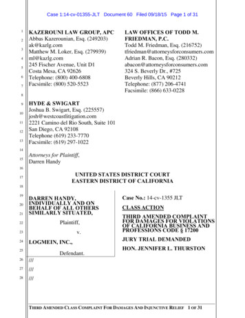
16INSTALLATION INSTRUCTIONSGM IGNITIONSWiring an HEI 4-pin Module (Magnetic Pickup Trigger).REMOVE MODULENOTE: The GM Ignition Module and condenser are removedand replaced with the supplied harness.INSTALL HARNESSGROMMETCONDENSERGM-CABLEHARNESSGM MODULEWIRE CLAMPSBLUELAUNCH(12V TO ACTIVATE)WHITEJUMPER HEAVY RED TO BATTERYPN 695HALL-EFFECT WHITE/BLUE(NOT USED)HEAVY BLACKTO BATTERYREDGRAYREDTO ENGINEGROUNDTACH OUTPUT B DNG C-SUPPLIEDHARNESSWHITE(NOT USED)KEYCONNECTORHEAVY REDOR PINK WIREFROM CARWIRING HARNESSCOVER WITH TAPEBLACK*ORANGE*GREEN (-)VIOLET ( )SUPPLIEDHARNESSMAGNETICPICKUPCONNECTOR*ORANGE - CONNECTS TO B *BLACK - CONNECTS TO C-BLACK*ORANGE*GM IGNITIONS Wiring an HEI 5
the Mallory Ignition Control. The cap should be clean inside and out especially the terminals and rotor tip. On vehicles with smaller caps, it is possible for the air inside the cap to become electrically charged causing crossfire which can result in misfire. This can be prevented by