Transcription
White paperCisco publicDCisco ACI and F5 BIG-IPDesign Guide 2021 Cisco and/or its affiliates. All rights reserved.Page 1 of 45
ContentsGoals of this sco ACI overview4F5 BIG-IP Overview9F5 design considerations25Multi-tenant design32F5 ACI ServiceCenter39Troubleshooting44For more information45 2021 Cisco and/or its affiliates. All rights reserved.Page 2 of 45
Goals of this documentThis document describes Cisco Application Centric Infrastructure (Cisco ACI ) and F5 BIG-IP LTM design anddeployment considerations.IntroductionThe document discusses load balancer design considerations and deployment options in Cisco ACI, specificallywith F5 BIG-IP from three aspects: network design, F5 design, and multi-tenant design. This document coversfeatures up to Cisco ACI Release 5.0.One of the key considerations of the network design with load balancer is to ensure incoming and return trafficgo through the same load balancer (one exception is direct server return (DSR), which doesn't have thisrequirement). There are various options you can use to insert the load balancer. One way is to use the loadbalancer as a gateway for servers or as a routing next hop for routing instances. Another option is to useSource Network Address Translation (SNAT) on the load balancer or use ACI Policy-Based Redirect (PBR) tomake the return traffic go back to the load balancer.Because it’s a stateful device, F5 BIG-IP requires seeing the return traffic in most designs but using it as thedefault gateway is not necessarily the best way to deploy it, and Cisco ACI can provide a better integration withthe use of a feature called Policy Based Redirect (PBR).F5 BIG-IP can be deployed in different high-availability modes. This document will cover the two common BIGIP deployment modes: active-active and active-standby. Various design considerations, such as endpointmovement during failovers, MAC masquerade, source MAC-based forwarding, Link Layer Discovery Protocol(LLDP), and IP aging will be discussed around each of the deployment modes.Multi-tenancy is supported by both Cisco ACI and F5 BIG-IP in different ways. This document will cover a fewways that multi-tenancy constructs on ACI can be mapped to multi-tenancy on BIG-IP. The discussion willrevolve around tenants, Virtual Routing And Forwarding (VRF), route domains, and partitions, and also multi tenancy, based on which BIG-IP form factor you use.The Cisco Application Policy Infrastructure Controller (APIC) is used to manage the ACI fabric. The F5 ACIServiceCenter is an application that runs on the APIC controller that augments the integration between ACI andF5 BIG-IP. This document will cover how the F5 ACI ServiceCenter application can be used to gain day-1 andday-2 operational benefits with joint deployment of F5 BIG-IP and Cisco ACI deployments.PrerequisitesTo best understand the network design presented in this document, you should have basic knowle dge aboutCisco ACI and F5 BIG-IP.Cisco ACI offers the capability to insert Layer 4 – 7 services, such as firewalls, load balancers, and IntrusionPrevention Systems (IPS), using a feature called a service graph. For more information, refer to the Cisco ACIservice-graph-design white paper at rastructure/white-paper-c11-734298.htmlThe service graph functionality can then be enhanced by associating to Policy-Based Redirect (PBR) policies.For more detailed information on PBR, refer to the Cisco ACI PBR white ructure/whitepaper-c11-739971.html 2021 Cisco and/or its affiliates. All rights reserved.Page 3 of 45
F5's BIG-IP product family comprises hardware, modularized software, and virtual appliances that run the F5TMOS operating system.To learn the basics of BIG-IP load balancing, refer to load-balancing-101-nuts-and-bolts.For other load balancing concepts, such as Source Network Address Translation (SNAT) and Automap, refer tohttps://support.f5.com/csp/article/K7820For BIG-IP modes of deployment, refer to https://support.f5.com/csp/article/K96122456#link 02 01TerminologyThis document uses the following terms with which you must be familiar: Bridge Domain (BD) Endpoint Group (EPG) Layer 3 Out or external routed network (L3Out) Subnet-based EPG in Layer 3 Out (L3Out EPG) Virtual Routing and Forwarding (VRF) Service graph Direct Server Return (DSR) Policy-Based Redirect (PBR) Load Balancer (LB) Route Health Injection (RHI) Source Network Address Translation (SNAT) MAC masquerade Self-IP - IP address on a BIG-IP interface associated with a VLAN Floating self-IP - IP address that two BIG-IP systems share. Any self-IP address that is assigned to afloating traffic group in BIG-IP is a floating self-IP address.Cisco ACI overviewCisco Application Centric Infrastructure (Cisco ACI) technology enables you to integrate virtual and physicalworkloads in a programmable, multi-hypervisor fabric to build a multiservice or cloud data center. The CiscoACI fabric consists of discrete components that operate as routers and switches, but it is provisioned andmonitored as a single entity. 2021 Cisco and/or its affiliates. All rights reserved.Page 4 of 45
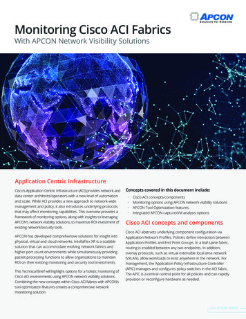
Cisco ACI physical topologyThe physical Cisco ACI fabric is built on a Cisco Nexus 9000 series spine-leaf design; its topology is illustratedin Figure 1, using a bipartite graph, where each leaf is a switch that connects to each spine switch, and nodirect connections are allowed between leaf nodes and between spine nodes. The leaf nodes act as theconnection point for all servers, storage, physical or virtual L4-L7 service devices, and external networks, andthe spine acts as the high-speed forwarding engine between leaf nodes. Cisco ACI fabric is managed,monitored, and administered by the Cisco APIC.Figure 1.Cisco ACI topologyCisco Nexus 9000 series switches that support ACI spine or leaf mode can be found /nexus-9000-series-switches/index.htmlThe minimum ACI fabric design should have two spine nodes, two leaf nodes, and three APICs.(Figure 1 illustrates four spine nodes and six leaf nodes.) The fabric design can scale up to 4 00 leaf nodes perACI fabric. See the latest ACI verified scalability guide for me.htmlAlthough Figure 1 shows a separate leaf node pair for APIC cluster, servers, storage, and others, it’s no tmandatory to use a separate leaf node. Even though there is no specific role configuration on each leaf, a leafconnected to the external network is called a border leaf.Cisco ACI logical constructsInstead of configuring individual switches in a fabric, the logical network and security are provisioned andmonitored as a single entity in the ACI fabric.The fundamental security architecture of the ACI solution follows a whitelist model. A contract is a policyconstruct used to define communication between Endpoint Groups (EPGs). Without a contract between EPGs,no unicast communication is possible between those EPGs by default. A contract is not required to allowcommunication between endpoints in the same EPG. 2021 Cisco and/or its affiliates. All rights reserved.Page 5 of 45
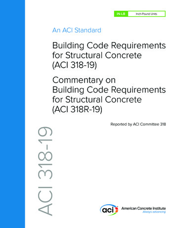
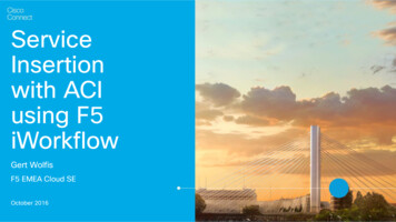
Figure 2 shows the relationship between EPGs and contracts.Figure 2.EPG and contractsAn EPG provides or consumes a contract (or provides and consumes a contract). For instance, the App EPG inthe example in Figure 2 provides a contract that the Web EPG consumes and consumes a contract that the DBEPG provides.An endpoint can belong to one EPG. Physical, virtual, and container endpoints can co -exist in the same EPG.How to define which EPG an endpoint belongs to is based on EPG type: L3Out EPG - based on the IP subnet (longest prefix match) EPG - based on the leaf interface and Virtual LAN (VLAN) ID, or leaf interface and Virtual Extensible LAN(VXLAN) uSeg EPG (also called micro-EPG) - based on IP, MAC VM attributes such as VM name, or acombination of IP, MAC, and those attributesFigure 3 illustrates ACI logical network design constructs. The tenant is a logical entity to construct EPGs,contracts, and network components for EPGs. Each EPG belongs to a Bridge Domain (BD) that is a broadcastdomain boundary in ACI. A BD belongs to a VRF.In this example, Web and App EPGs are in the same BD, BD1, and DB EPG is in a dedicated BD, BD2. Unliketraditional networks, multiple different EPGs can be in the same subnet as different security groups and zones.Figure 3.ACI logical network construct 2021 Cisco and/or its affiliates. All rights reserved.Page 6 of 45
Cisco ACI Service Graph and Policy-Based Redirect (PBR)The Layer 4 – 7 Service Graph is a feature in Cisco ACI to insert Layer 4 – 7 service devices such as a firewall,load balancer, and IPS between the consumer and provider EPGs. Service Graph itself is not mandatory todesign Layer 4 – 7 service devices in ACI, as long as the Layer 4 – 7 devices are inserted in the network usingthe general routing and bridging.Figure 4 provides an example using routing and bridging to insert a load balancer without Service Graph. Forincoming traffic from an endpoint in the consumer EPG, the VIP is routed by the ACI fabric. Why? Because theVIP is an ACI internal endpoint if the gateway of the server is the load balancer; the return traffic from anendpoint in the provider EPG is simply bridged by the ACI fabric.Figure 4.Load balancer design without SNAT or PBR 2021 Cisco and/or its affiliates. All rights reserved.Page 7 of 45
If the load balancer interface and the servers are not in the same subnet, the use of SNAT on the load balancercan make the return traffic back to the load balancer. Even if the use of Service Graph is not mandatory in thiscase, the use of Service Graph offers these advantages: ACI automatically manages VLAN deployment on the ACI fabric and the virtual networks for service nodeconnectivity. ACI automatically connects and disconnects virtual Network Interface Cards (vNICs) for virtual serviceappliances. ACI provides a more logical view of service insertion between consumer and provider EPGs. ACI can redirect traffic to the service node without the need for the service node to be the defaultgateway of the servers.One of the main advantages of Service Graph is the PBR feature, which is helpful to insert Layer 4 – 7 servicedevices. With this PBR feature, ACI redirects traffic matched with the contract without relying on routing orbridging. For load balancer designs, PBR can be used for return traffic generated from the servers to make thereturn traffic go back to a load balancer that doesn’t perform SNAT.Figure 5 illustrates this with an example. The incoming traffic from an e ndpoint in a consumer EPG to VIPdoesn’t require PBR because it’s routed to the VIP that is also an ACI internal endpoint. For the return trafficfrom an endpoint in the provider EPG, PBR is required if the load balancer didn’t perform SNAT on the incomingtraffic. Without PBR, traffic would directly go back to the consumer endpoint, which prevents the load balancerfrom seeing both directions of the traffic. 2021 Cisco and/or its affiliates. All rights reserved.Page 8 of 45
Figure 5.ACI Service Graph PBR use case for load balancer designNote:Service Graph is mandatory in order to use PBR.For more detailed information on Service Graph design and PBR, refer to the following white papers: Service Graph Design with Cisco Application Centric Infrastructure White ricinfrastructure/white-paper-c11-734298.html Cisco Application Centric Infrastructure Policy-Based Redirect Service Graph Design White ucture/white-paper-c11-739971.htmlF5 BIG-IP OverviewF5 BIG-IP is a family of products covering software and hardware designed around application availability,access control, and security solutions. When referring to BIG-IP this can mean a single software module in BIGIP's software family or it could mean a hardware chassis sitting in your data center.BIG-IP hardwareBIG-IP hardware offers several types of purpose-built custom solutions. There are two primary variations ofBIG-IP hardware: single chassis design or VIPRION modular designs.For more information refer to: s-applianceBIG-IP softwareBIG-IP software products are licensed modules that run on top of F5's Traffic Management Operation System(TMOS). This custom operating system is an event-driven operating system designed specifically to inspectnetwork and application traffic and make real-time decisions based on the configurations you provide. The BIGIP software can run on hardware or can run in virtualized environments. Virtualized systems provide BIG -IPsoftware functionality where hardware implementations are unavailable, including public clouds and variousmanaged infrastructures where rack space is a critical commodity.There are a number of software modules offered by F5 BIG-IP. The BIG-IP Local Traffic Manager (LTM) is thesoftware module that we focus on while discussing design and other considerations in this document. 2021 Cisco and/or its affiliates. All rights reserved.Page 9 of 45
BIG-IP LTM is central to F5's full traffic proxy functionality. It provides the platform for creating virtual servers,performance, service, protocol, authentication, and security profiles to define and shape application traffic.Most other software modules in the BIG-IP family use LTM as a foundation for enhanced services.All variations of BIG-IP hardware and software work with Cisco ACI. If the virtual edition of BIG-IP is being used,a VMM integration, such as VMware vSphere or Microsoft SCVMM, can be done with Cisco APIC.For ACI VMM domain integration, see the Cisco ACI Virtualization Guide ml and review the ACI network design options for loadbalancer.This section explains typical network design options for load balancer in general and then explains how totranslate these options to an ACI network construct.OverviewWhen inserting a load balancer into a Cisco ACI fabric, it is important to understand the desired traffic flowThere are two main types of traffic patterns to consider:1. Incoming and return traffic go through the same load balancer that is a stateful device2. The traffic to the other VIP goes via a load balancer and the return traffic from servers goes directlyback to the client: this is called Direct Server Return (DSR)Following is a list of questions that helps to understand the requirement. Is the load balancer deployed in Layer 2 or Layer 3 mode? (F5 BIG-IP supports both Layer 2 and Layer 3- see https://support.f5.com/csp/article/K55185917) How is the return traffic handled? Is the load balancer the gateway? Is the load balancer doing SNAT? IsACI PBR redirecting the traffic to the load balancer or is the load balancer deployed in DSR mode? What High-Availability (HA) option is used for the load balancer - active/standby HA pair, active/activeHA pair, or multiple HA pairs? Is the VIP in the same subnet range as the IP address of a load balancer interface (F5 BIG-IP calls it“self-IP”) or outside of the subnet range? What are the dynamic routing protocol requirements? Is Route Health Injection (RHI) required or not?In this document, the assumption is that the load balancer is deployed in Layer 3 mode with active/standby HAbecause this represents the majority of the deployments.Figure 6 illustrates common load balancer network design options. In the first example on the left side of the image, the load balancer is deployed in two-arm mode and it isthe default gateway of the servers. SNAT or PBR is not required because the load balancer is in thetraffic path based on routing. In the second example, the load balancer is deployed in two-arm mode and it is placed between twodifferent routers or VRFs: one is for external connectivity and the other is the gateway of servers. SNATor PBR is not required because the load balancer is in the traffic path based on routing. 2021 Cisco and/or its affiliates. All rights reserved.Page 10 of 45
In the third example, the load balancer is deployed in two-arm mode in a way that not all traffic from theservers has to go via the load balancer itself. SNAT or PBR is required to make return traffic back to theload balancer. If neither SNAT nor PBR is used, the return traffic would go back to the client directly, andas a result, the traffic would be dropped by the client. The reason: because the source IP address of thereturn traffic (of the server) is different from the destination IP address of the incoming traffic sent by theclient, which was directed to the VIP. In the fourth example, the load balancer is deployed in one-arm mode in a way that not all traffic fromthe servers has to go via the load balancer itself. SNAT or PBR is required to make return traffic back tothe load balancer. If neither SNAT nor PBR is used, the return traffic goes back to the client directly,which will be dropped by the client because the source IP address of the return traffic is different fromthe destination IP address of the incoming traffic sent by the client. The load balancer interface can be inthe same or a different subnet with servers. This design can be used for Layer 2 DSR, where the returntraffic doesn’t go back via the load balancer. For Layer 2 DSR, the load balancer and servers must be inthe same subnet.Figure 6.Typical load balancer design optionsLoad balancer designs are often categorized using the terminology “two-arm” and “one-arm”. From the loadbalancer’s perspective, the number of arms is nothing more than the number of interfaces or VLAN interfacesthat are created on the load balancer. There should be no significant difference between the two modes from aload balancer performance perspective. In the case of a two-arm design, traffic from the client arrives on aninterface on the load balancer and is forwarded to a server through the other interface. In the case of a one -armdesign, traffic arrives and leaves using the same interface on the load balancer.The following sub-sections explain how to translate the typical load balancer design options just described intoACI network constructs. Table 1 summarizes the comparison of the design options in a Cisco ACI fabric.In these examples, the load balancer external interface IP and the VIP are in the same subnet. For the cas ewhere they are not in the same subnet, refer to the VIP outside of the self IP subnet range section. Even if theexamples reference north-south traffic flows, which is traffic from the outside to internal servers through a VIP,the same design considerations can also be applied to east-west traffic flows, which is traffic from internalservers to other internal severs through a VIP. 2021 Cisco and/or its affiliates. All rights reserved.Page 11 of 45
Table 1.Typical load balancer design options in Cisco ACI fabricHow to make the returntraffic go back via theLoad Balancer (LB)DesignBenefitConsiderationTwo-arm (inline) LBas gatewayLB is the gateway for theserversUse LB as the gatewayfor the serversassociated to the VIPSimple networkdesignInter-subnet trafficmust go through theload balancer.Two-arm (inline) LBFabric as gatewayLB as routing next hop(VRF sandwich)Use the ACI fabric as aTake advantage ofgateway for the servers the ACI anycastassociated to the VIP.gateway.LB is routing next hop ofthe ACI fabric.Need to manage twoVRFsTwo-arm LBSNAT or PBRUse the ACI fabric as agateway for the LB andalso for the serversassociated to the VIP.Use SNAT or PBR tomake return traffic goback via the LB.Take advantage ofthe ACI anycastgateway.Service Graph ismandatory to use PBRUse the ACI fabric as agateway for the LB andalso for the serversassociated to the VIP.Use SNAT or PBR tomake return traffic backto load balancer.Take advantage ofthe ACI anycastgateway.Fabric as gatewayOne-arm LBFabric as gateway*SNAT or PBR*Selective trafficredirection by usingPBRService Graph ismandatory to use PBRSelective trafficredirection by usingPBRThis design can be used for Layer 2 DSR where the return traffic doesn’t go back via the load balancer (the details are not c overed in thisdocument.)Two-arm (inline) load balancer as gatewayThe first example is one where the two-arm inline load balancer is the default gateway of the servers. SNAT orPBR is not required because the load balancer is in the traffic path based on routing. In this case, two VLANsegments are required. Thus, in case of ACI, you need to use two bridge domains: one is for the load balancerexternal interface and the other is for the load balancer internal interface. Figure 7 provides an example of thisscenario. In this example, the load balancer VIP and the load balancer external interface IP are in the samesubnet. 2021 Cisco and/or its affiliates. All rights reserved.Page 12 of 45
Figure 7.Two-arm (inline) load balancer as gateway“LB-Ext” bridge domain for the load balancer external interface has the bridge domain subnet that is thegateway for the load balancer to the external network through L3Out. The “Web” bridge domain for the loadbalancer internal interface and the servers doesn’t have a bridge domain subnet because the load balancerinternal IP address is the gateway for the servers. The L3Out connected to the external network has the L3OutEPG “External” with the external network subnets that are allowed to access the load balancer VIP in the “LBExt” bridge domain.The traffic coming from the external network arrives to the ACI fabric and it is routed to the VIP(192.168.10.100) because the VIP is an ACI local endpoint in “LB -Ext” bridge domain. The traffic is then loadbalanced to one of the servers associated to the VIP. The return traffic from the server arrives on the loadbalancer internal interface because it is the gateway of the servers. The load balancer then routes the trafficback to the ACI fabric that is the gateway of the load balancer to the external network.Figure 8 illustrates the contract configuration for this design. To permit end-to-end traffic, one of the followingconfigurations is required: Two contracts – One is between the L3Out EPG “External” for the external network and the EPG “LB Ext” for the load balancer external interface, and the other is between the EPG “LB -In” for the loadbalancer internal interface and “Web” EPG for the servers. All EPGs are created by a user. One contract – If there is no security requirement, the load balancer internal interface and the serverscan be combined into one EPG instead of different EPGs with a contract. All EPGs are created by a user. Service Graph – Use Service Graph on a contract between the L3Out EPG “External” for the externalnetwork and “Web” EPG. The EPGs (called “internal service EPGs” or “shadow EPGs”) for the loadbalancer external and internal interfaces are automatically created through Service Graph rendering. Theinternal service EPGs are not displayed in the GUI, and the user doesn’t need to manage them. 2021 Cisco and/or its affiliates. All rights reserved.Page 13 of 45
Figure 8.Two-arm (inline) load balancer as gateway (ACI network and contract design)Highlights of key characteristics of this design: The load balancer internal interface and the EPG for the servers are in the same bridge domain (ACI isused for bridging) ACI can be used as the next hop for the external side of the load balancer All inter-subnet traffic goes through the load balancer SNAT or PBR is not required Service Graph is not mandatoryTwo-arm (inline) load balancer with fabric as gatewayThis design consists of a two-arm inline load balancer placed between two routing instances, such as twoseparate routers or two VRFs. The internal facing routing instance provides the gateway to the servers. SNAT orPBR is not required because the load balancer is in the traffic path based on routing. In the case of ACI, you canuse two VRFs (instead of using an external router): one is for the load balancer external interface and the otheris for the load balancer internal interface. The two VRFs configured in ACI are not for the purpose ofmultitenancy, but simply to route traffic via the load balancer. No inter-VRF route-leaking configuration isrequired on the ACI fabric itself because the load balancer is in between VRFs.Figure 9 provides an example of this configuration. In this example, the load balancer VIP and the load balancerexternal interface IP are in the same subnet. 2021 Cisco and/or its affiliates. All rights reserved.Page 14 of 45
Figure 9.Two-arm (inline) load balancer with the fabric as gatewayThe external-facing VRF, “VRF1”, has the L3Out connected to the external network and the L3 bridge domain,“LB-Ext”, that has the gateway for the load balancer to the external network. The L3Out connected to theexternal network has the L3Out EPG “External” with the external network subnets that are allowed to access tothe load balancer VIP in the “LB-Ext” bridge domain. The internal-facing VRF, “VRF2”, has the L3 bridgedomain, “Web”, that is the gateway for the servers and the L3Out “LB-In” for the load balancer internalinterface connectivity. The L3Out “LB-In” has the L3Out EPG “LB-In” with the external network subnets that areallowed to access to the servers through the load balancer.The traffic coming from the external network arrives on the ACI fabric on VRF1 and it is routed to the VIP(192.168.10.100) because the VIP is an ACI local endpoint in “LB -Ext” bridge domain. Traffic is then loadbalanced to one of the servers associated to the VIP. The load balancer must have a route to the server subnet(10.10.10.0/254). This load balancer route uses the ACI IP address on the L3Out logical interface of the L3Out“LB-In” and then traffic arrives on the servers in VRF2. The return traffic from the server arrives on the ACIfabric via the “Web” bridge domain on VRF2 because the “Web” bridge domain subnet is the gateway of theservers. ACI VRF2 must have a route to the external network via the load balancer internal interface. Then, theload balancer routes the traffic back to the ACI leaf that is the gateway of the load balancer to the externalnetwork.If the load balancer does SNAT and uses the load balancer internal IP subnet range as NATe’d IP, the loadbalancer internal interface can be in a bridge domain instead of an L3Out because the NATe’d IP is a localendpoint IP in VRF2 that doesn’t require an additional route. 2021 Cisco and/or its affiliates. All rights reserved.Page 15 of 45
Figure 10 illustrates the contract configuration for this design. To permit end-to-end traffic, one of the followingconfigurations is required: Two contracts – One is between the L3Out EPG “External” for the external network and the EPG “LB Ext” for the load balancer external interface, and the other is between the L3Out EPG “LB -In” for theload balancer internal interface and “Web” EPG for the servers. All EPGs are created by a user. Service Graph – Use of Service Graph on a contract between the L3Out EPG “External” for the externalnetwork and “Web” EPG. L3Out EPG “LB-In” for the load balancer internal interface needs to be createdseparately and is selected in the Service Graph. The EPG “LB-Ext”, internal service EPG, for the loadbalancer external interface is automatically created through Service Graph rendering. The internal serviceEPG is not displayed in the GUI, and the user doesn’t need to manage it.Figure 10.Two-arm (inline) load balancer with fabric as gateway (ACI network and contract design)Key characteristics of this design: This is the traditional VRF sandwich design ACI is used for routing The external interface of the load balancer is connected to a bridge domain via an EPG The internal interface of the load balancer is connected to a L3Out via a L3Out EPG All inter-VRF traffic goes through the load balancer SNAT or PBR is not required Service Graph is not mandatory If SNAT is enabled on the load balancer using the internal interface subnet range as NAT’ed IP, L3Out forthe internal interface of the load balancer is not required 2021 Cisco and/or its affiliates. All rights reserved.Page 16 of 45
Two-arm load balancer with fabric as the gatewayThis design describes the integration with a two-arm load balancer in a way that not all traffic from the servershas to go via the load balancer itself. SNAT or PBR is required to make the return traffic go back to the loadbalancer. Without the use of SNAT or PBR, the return traffic from the servers would bypass the load balancerand then the client that receives the return traffic doesn’t handle the traffic as the reply because the source IPaddress of the return traffic is different from the destination IP address of the traffic sent by the client.Figure 11 provides an example of this scenario. This example consists three bridge domains: one is for theexternal interface of the load balancer, another is for the internal interface of the load balancer, and the third isfor the servers. If the servers and the internal interface of the load balancer are in the same subnet, the twobridge domains can be combined to one bridge domain. In this example, the load balancer VIP and the loadbalancer external interface IP are in the same subnet.Figure 11.Two-arm (inline) load balancer with fabric as gatewayThe “LB-Ext” bridge domain for the load balancer external int
The document discusses load balancer design considerations and deployment options in Cisco ACI, specifically with F5 BIG-IP from three aspects: network design, F5 design, and multi-tenant design. This document covers