Transcription
Paralleling PowerSystem DesignConsiderationsand System LevelControlPowerHour webinar series for consulting engineersExperts you trust. Excellence you count on.August 22nd, 2019 11:00 PDT / 13:00 CDT(1PDH issued by Cummins)
Welcome!PowerHour is designed to help our engineer partners to Keep up to date on products, technology, and codes and standards development Interact with Cummins experts and gain access to ongoing technical support Participate at your convenience, live or on-demand Earn Professional Development Hours (PDH)Technical tips: Audio is available through teleconference, or your computer (don’tforget to unmute) You are in “listen only” mode throughout the event Use the WebEx Q&A Panel to submit questions, comments, andfeedback throughout the event. We will provide sufficient Q&A time afterpresentation If you lose audio, get disconnected, or experience a poor connection,please disconnect and reconnect Report technical issues using the WebEx Q&A Panel, or emailpowergenchannel@cummins.com2
Meet your panelistsCummins presenter:Cummins facilitator:HighResolutionHeadshotHassan R ObeidGlobal Technical Advisor – Systems and ControlsCummins Inc.Your local Cummins contacts: Western Canada: Ian Lindquist (ian.Lindquist@cummins.com), Western Canada Region Eastern Canada: Gianluca Ianiro (gianluca.ianiro@cummins.com), Eastern Canada Region AZ, ID, NM, NV: Carl Knapp (carl.knapp@cummins.com), Rocky Mountain Region CO, MT, ND, UT, WY: Chris Scott (chris.scott@cummins.com), Rocky Mountain Region Northern IL, IA: John Kilinskis (john.a.kilinskis@cummins.com), Central Region UP of MI, MN, East ND, WI: Michael Munson (michael.s.munson@cummins.com), Central Region NE, SD, West MO, KS: Earnest Glaser (earnest.a.glaser@cummins.com), Central RegionTom Bakritzes,Global Sales Training ManagerCummins Inc. South IL, East MO: Jeff Yates (jeffrey.yates@cummins.com), Central Region TX, OK, AR, LA, MS, AL, Western TN: Scott Thomas (m.scott.thomas@cummins.com), Gulf Region FL, GA, NC, SC, Eastern TN: Robert Kelly (robert.kelly@cummins.com), South Region NY, NJ, CT, PA, MD: Charles Attisani (charles.attisani@cummins.com), East Region CA, HI: Brian E Pumphrey (brian.pumphrey@cummins.com), Pacific Region WA, OR, AK: Tom Tomlinson (tom.tomlinson@cummins.com), Pacific Region For other states and territories, email powergenchannel@cummins.com or r3
DisclaimerThe views and opinions expressed in thiscourse shall not be considered the officialposition of any regulatory organization andshall not be considered to be, nor be reliedupon as, a Formal Interpretation.Participants are encouraged to refer to theentire text of all referenced documents. Inaddition, when it doubt, reach out to theAuthority Having Jurisdiction.4
Course ObjectivesParalleling Power System Design Considerations and System LevelControlThis course provides an overview of power systems design and covers when and how a system levelcontrol fits in the power system. System level control reliability will be explored while the instructor reviewsparalleling and control strategies employed to eliminate potential single points of failure. This course alsocovers the elements to consider for designing paralleling systems, automatic transfer switches, grounding,and protection.After completing this course, participants will be able to: Discuss the major differences between switchboards and switchgear (UL891 and UL 1558) Describe transfer switch design considerations in a power system scheme Describe the functionalities and applications of a system level control and how it fits in a power system Discuss protection and ground fault considerations5
Power System Building BlocksGenerator Sets with IntegratedParalleling Control & Protection155025513281UProtectionOAFMSystem Level Control155025513281UGridDigital Cloud SolutionsDistribution BoardPP50 GQ51 GQ51N50NOAFMGroundingTransfer Switches155025513281UOAFM6
Integrated Autonomous Paralleling Control Paralleling functions are part of the generator set control: First start arbitration Synchronizing (Ø, V, Hz) Load sharing (kW and kVAR) Generator set protection Metering and alarms Built-in safe manual paralleling Generation to load consumption matching Distributed logic architecture No paralleling master control Single point of failure eliminated Consistent design Easier to learn, operate, and troubleshoot Reduce wiring and footprint compared with traditionalswitchgear parallelingControl wiresCBCBCB Common point of power connection Bus tap (Generator mounted breakers) Switchboard/Switchgear7
Integrated Autonomous Paralleling Control Paralleling functions are part of the generator set control: First start arbitration Synchronizing (Ø, V, Hz) Load sharing (kW and kVAR)Spec Note Each generator set shall be designed to be completely Generator set protectionautonomous and capable of providing all specified functions and Metering and alarmsperformance without any external control. Built-in safe manual paralleling Generation to load consumption matching Distributed logic architecture No paralleling master control Single point of failure eliminated Consistent design Easier to learn, operate, and troubleshoot Reduce wiring and footprint compared with traditionalswitchgear parallelingCBCBControl wiresCB Common point of power connection Bus tap (Generator mounted breakers) Switchboard/Switchgear8
Power System Building BlocksGenerator Sets with IntegratedParalleling Control & Protection155025513281UProtectionOAFMSystem Level Control155025513281UGridDigital Cloud SolutionsDistribution BoardPP50 GQ51 GQ51N50NOAFMGroundingTransfer Switches155025513281UOAFM9
Distribution Boards Distribution board is a means of controlling and distributingelectrical power Distribution boards are metal structures comprised only of"power sections" and their related components Switching devices: breakers, fuses Conductors: bus bars, cables Transformers: voltage, current Protection: protective devices Voltages and standards: Low Voltage Medium Voltage UL, ANSI, CSA, IEC10
LV Switchboards vs. Switchgear Switchboard Switchgear UL891 UL1558 (IEEE C37.20.1 design & NEMA C37.51 test) Dead-front Switchboard Metal-enclosed power circuit breaker switchgear Circuit breakers are typically UL489 MCCB/ICCB Circuit breakers are UL1066 (LVPCB) Can contain UL-1066 breakers No molded case circuit breakers Circuit breakers not required to be in individualcompartments Circuit breakers required to be in separate metalcompartments Evaluated for short-circuit 0.05s (3 cycles) ONLYand NO short-time test Evaluated for short-circuit 0.067s (4 cycles) andshort-time 0.5s (30 cycles) Instantaneous trip-response is required Instantaneous can be turned off Short-circuit 150KAIC, e.g. Short-circuit 200KAIC, e.g. Basic office, commercial building, and retail Healthcare, hospitals UL1558 Switchgear can be 25%-30% moreexpensive than UL891 Switchboard11
LV Switchboards vs. Switchgear Switchboard Switchgear UL891 UL1558 (IEEE C37.20.1 design & NEMA C37.51 test) Dead-front Switchboard Metal-enclosed power circuit breaker switchgear Circuit breakers are typically UL489 MCCB/ICCB Circuit breakers are UL1066 (LVPCB) Can contain UL-1066 breakers No molded case circuit breakers Circuit breakers not required to be in individual Circuit breakers required to be in separate metalcompartmentscompartmentsSpec Note Evaluate the project requirementsand specify a Evaluated for short-circuit0.05s(3 cycles)ONLY board accordingly.Evaluated for short-circuit 0.067s (4 cycles) andUL891or 1558distributionand NO short-time testshort-time 0.5s (30 cycles) Instantaneous trip-response is required Instantaneous can be turned off Short-circuit 150KAIC, e.g. Short-circuit 200KAIC, e.g. Basic office, commercial building, and retail Healthcare, hospitals UL1558 Switchgear can be 25%-30% moreexpensive than UL891 Switchboard12
MV Switchgear 1kV – 38kV No protection built-in the circuit breakers. External protection must be added Metal enclosed switches and metal-clad Metal-clad The main switching and interrupting device is of drawout type All live parts are enclosed within grounded metal compartments Primary bus conductors and connections are covered withinsulating material Automatic shutters Some of US Standards for switchgear over 1000 V IEEE C37.04 rating structure for circuit breakers C37.09 Test Proc for circuit breaker C37.20.2 Metal Clad switchgear C37.20.3 Metal-Enclosed switchgear C37.20.7 switches for use in Metal-Enclosed switchgear C37.74 Pad-Mounted switchgear13
Concept CheckWhich of the following statements is true?a) Switchgear contains UL 489 MCCB & ICCB and UL1006 power breakersb) Switchboards evaluated for short-time 0.5 seconds (30 cycles)c) Switchboards evaluated for short-circuit 0.067s (4 cycles)d) Switchgear evaluated for short-time rating 0.5 seconds (30 cycles)14
Concept CheckWhich of the following statements is true?a) Switchgear contains UL 489 MCCB & ICCB and UL1006 power breakersb) Switchboards evaluated for short-time 0.5 seconds (30 cycles)c) Switchboards evaluated for short-circuit 0.067s (4 cycles)d) Switchgear evaluated for short-time rating 0.5 seconds (30 cycles)15
Power System Building BlocksGenerator Sets with IntegratedParalleling Control & Protection155025513281UProtectionOAFMSystem Level Control155025513281UGridDigital Cloud SolutionsDistribution BoardPP50 GQ51 GQ51N50NOAFMGroundingTransfer Switches155025513281UOAFM16
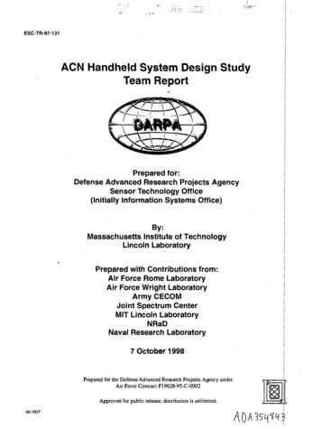
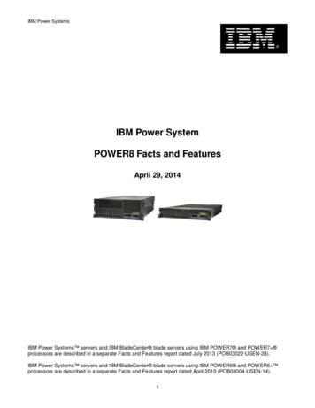
ATS ConsiderationOCPDAvailable Fault Current:150,000AMinimum WCR:150,000A Per UL1008, ATSs must have a short-circuit ratingcalled Withstand and Closing Rating (WCR) WCR can either be based on: Time Specific device ATSs must be capable of withstanding theavailable fault current at their line side terminalsand protected by an OCPD selected appropriately ATSs may have a short-time ratingOCPDAvailable Fault Current:100,000AMinimum WCR:100,000AOCPDAvailable Fault Current:65,000AMinimum WCR:65,000AOCPD: Overcurrent Protection Device17
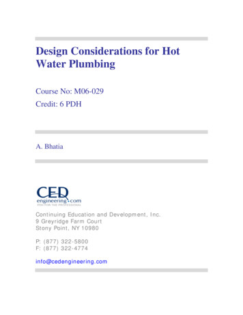
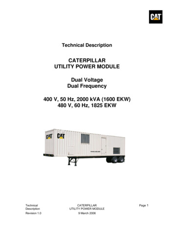
ATSCoordinationFigure 1Figure 2UL891 SwitchboardUL1558 SwitchgearBreaker has instantaneoustrip responseBreaker has short-time tripresponse. Instantaneousis turned OFFAFC: 42,000AAFC: 65,000AShort-Circuit Rating:65,000A @600 VACfor 0.05 seconds (3 Cycles) In Figure 1, the ATS is fed by a UL891 switchboard The circuit breaker must include aninstantaneous trip response Circuit breaker must trip in 0.05s (3 cycles) orfasterShort-Circuit Rating:42,000A @600 VACfor 0.5 seconds (30 Cycles) AFC: Available Fault CurrentIn Figure 2, the ATS is fed by a UL1558 switchgear UL-1066 breaker have a short-time trip response, ATSmay need to have a short-time rating The circuit breaker must include an instantaneous tripresponse unless the available short circuit current is lessthan or equal to short-time rating of the transfer switch When protected with a circuit breaker with a short-timetrip response, the short-time response of the circuitbreaker must be coordinated with short-time currentrating of the ATS18
Concept CheckTransfer Switches fed by UL891 board must have a short-timerating of, e.g.,18 cycles or 30 cycles:a) Trueb) False19
Concept CheckTransfer Switches fed by UL891 board must have a short-timerating of, e.g.,18 cycles or 30 cycles:a) Trueb) False20
Power System Design21
Power System Building BlocksGenerator Sets with IntegratedParalleling Control & Protection155025513281UProtectionOAFMSystem Level Control155025513281UGridDigital Cloud SolutionsDistribution BoardPP50 GQ51 GQ51N50NOAFMGroundingTransfer Switches155025513281UOAFM22
System Design Consideration Project Scope Sequence of Operation Plans and Specifications System voltage, wires, and frequency 480V, 600V, 13.8kV, 3Phase/4Wire, 3Phase/3Wire 50/60Hz23
Distribution Board Considerations Distribution board codes and standards CSA 22.2, UL891, UL1558 – Low Voltage IEEE (C37.20.2) and NEMA – Medium Voltage Bus rating and bracing 2000A, 3000A, 4000A, 5000A (LV) 1200A, 2000A, 3000A (MV) 65KAIC, 100KAIC, 200KAIC Bus type and insulation Copper, aluminum Silver-plated, tin-plated Insulated Enclosure types NEMA1, NEMA3R (Walk-In, Non Walk-In) Control voltage for the circuit breakers 24VDC, 48VDC, 125VDC, 120VAC CPTs (Control Power Transformers) Station batteries with charger and alarms Surge arrestors and capacitors and their classes Arc flash reduction switches Real estate available Conduit entry Top, bottom, sides Protection – grounding and coordination Rear and front door types Hinged, bolts, door handles, locks Accessories and spare parts Utility connection and type of connection and operation24
Utility Connection ConsiderationsGG Understand the intertie agreement with the utility Utility connections: Hard-closed 100ms or less Some utilities allow longer time Soft-ramp: long enough to ramp the load Time is determined by the utility and AHJ Extended paralleling: indefinite amount of time Peak shave/base load Demand response Protection Sync check, reverse power, under/over voltage &frequency, and lockout External max parallel timer (depends on the application)25
Power System ExamplesExample 1 An office requires a 120kW backup power whenthe normal source fails - open transition: A generator set and a transfer switchControlGATS26
Paralleling GeneratorsExample 2 An application requires paralleling two 500kWgenerator sets (campus building): Two generator sets with paralleling control Point of common connection- Switchboard, e.g., with two electricallyoperated (EO) circuit breakersControlControlGGEOEO480VAC, 3PH, 4W, 60Hz, 100kAPoint of common connection: switchgear/switchboard27
Adding Load Control CapabilityExample 2 Cont. If we add three transfer switches to the projectin Example 2 and also add a feature for priorityload add/shed on the transfer switchesControlControlGG NEC 2017- 700.4 (B)EOPoint ofcommonconnection:switchgear/switchboardEO480VAC, 3PH, 4W, 60Hz, 28
Utility Paralleling ExampleExample 3 One utility and one generator set (LV or MV) Open/Closed transition Extended paralleling: peak shave/base loadG Point of common connectionPoint of commonconnection: switchgear/switchboard Switchboard, e.g. with two electrically operatedcircuit breakers Controller: to perform the sequence of operation e.g. generator set controllerEOEO Utility breaker protection: 25, 27, 32R, 59, 81O/U and 86 e.g. SEL 75129
System Level ControlExample 4 Extensive sequence of operation with layers of failure logic Parallel multiple generators with a utility or multiple utilitiesGGGG Multi system level breaker control Utility main breakers Generator main breakers Tie breakers Downstream feeders and transfer switches A touchscreen operator interface HMI with SLD Reports (e.g. JCAHO), alarms, trending Redundant processors and redundant I/O A system level control is a solution! Applications: Healthcare, Data Centers, Water/WasteWater. Limitless!30
31
System Level Control Reliability Failure of the system level control shall not jeopardize the overallpower system reliability Some of the components that can fail: HMI (screen) PLC Networking devices: I/O cards, communication Failures must be analyzed and mitigated so the system fails gracefully Continuous system diagnostics of controller, network, and I/Ocards With HMI failure, the system should be able to transfer power System can be operated manually if needed Generators can be started manually Generators can be paralleled manually through their localcontrol/HMI Unexpected events, i.e. racking out a UM breaker while thesystem in Auto32
Failure Design Rule Example Breaker States: Open Closed Unknown If the status is unknown,then how does the systembehave? Failures must be analyzedand mitigated33
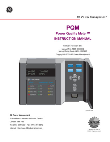
System Level Control ontrolControlControlGGGGTwo common buseswith splitTwo Transfer pairswith split busControlControlControlControlGGGGTwo Transfer pairswith bypass34
System Level Control ontrolControlControlGGGGTwo common buseswith splitTwo Transfer pairswith split NotebusSpecSpecify an independent system level control with analyzed and mitigated failuresmodes to monitor and control the operation of the entire paralleling power system.ControlControlControlControlGGGGTwo Transfer pairswith bypass35
Power System Building BlocksGenerator Sets with IntegratedParalleling Control & Protection155025513281UProtectionOAFMSystem Level Control155025513281UGridDigital Cloud SolutionsDistribution BoardPP50 GQ51 GQ51N50NOAFMGroundingTransfer Switches155025513281UOAFM36
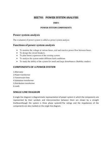
Protection Typical protection (not inclusive):BreakerLow VoltageMedium VoltageIntegrated with the breakerDiscreet external relayFeederLSI, LSIG50/51, 50/51N, 51G, 86Gen ParallelingLSI, LSIA50/51, 50/51N, 51G, 86UtilityLSI, LSIGExternal Relay: 25, 27, 32R, 59, 81O/U & 8625, 27, 32R, 50/51, 59, 81O/U, 86TieLSI, LSIG, External Relay: 2550/51, 25, 86 Other protection considerations: 81R 87 AFDGG87:Zone37
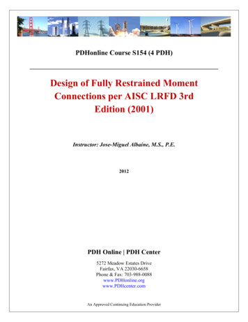
M1Zone 3BusDifferentialZone 152-GM252-UM2Zone 252-G1Generator SetDifferentialIs it necessary?52-F1 86 Lockout87 Differential52-F252-F352-F452-F552-F638
Protection: Generator Set15 – Synchronizer (Ø, V, Hz)25 – Synch Check27 – Undervoltage32 – Directional Power40 – Loss of Excitation/Reverse kVAR46 – Phase Balance Current47 – Phase Sequence Voltage50 – Instantaneous overcurrent51 – Time Overcurrent59 – Overvoltage81U/O – Under/Over FrequencyArc Flash Maintenance Mode39
Protection: Generator Set15 – Synchronizer (Ø, V, Hz)25 – Synch Check27 – Undervoltage32 – Directional Power40 – Loss of Excitation/Reverse kVAR46 – Phase Balance Current47 – Phase Sequence VoltageSpec Note Each generator setbe providedwith integral protection50 –shallInstantaneousovercurrentfunctions to prevent damage51on–overloador overcurrent condition.Time Overcurrent59 – Overvoltage81U/O – Under/Over FrequencyArc Flash Maintenance Mode40
Grounding: Why Is It Required? It provides common reference for the different power sources It prevents voltages from rising to dangerous levels Safety to working personnel and equipment It is required by code It provides the path for ground fault current to return back to the source thus allowing current detection relays tooperate and isolate the fault sourceNEC 230.95 (CEC 14-102)Ground Fault Protection (GFP) of equipment is required at the service disconnect (utility breaker) for systems with: Solidly grounded wye electrical service More than 150 volts to ground (277/480 or 347/600VAC) Overcurrent device rating of 1000A or more (CEC 120/208VAC & 2000A)NEC 700.6 (D)Ground Fault Indication (GFI) is required at the emergency source41
Questions To Consider For GroundingSchemes Is the system 3Ph/3Wire or 3Ph/4Wire? Are the ATSs in the system 3-Pole or 4-Pole? Is the system open transition or closed transition? Does the system have multiple grounds? For example: utilities are grounded at source and generator sets are grounded in switchgear Are there tie breakers between the source breakers? Is there space available to install 4-Pole breakers instead of 3-Pole breakers in open transition system? Does the utility breaker have LSIG trip unit and do generator breakers have LSIA trip units? All of the above will help in narrowing down the number of solutions to properly ground the system42
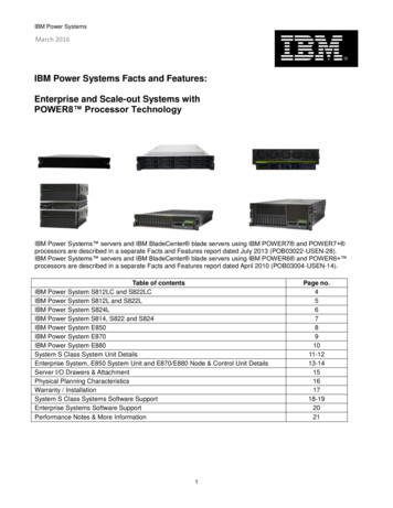
Grounding ExampleUtilityG1 3Ph/4Wire Open transition :Y Utility grounded at the source Generator grounded in the gearG2LSIALSIGLSIA Breakers are 3-Pole LSIG on the utility LSIA on the generatorsNeutralNeutral 4-Pole ATSs must be used4PoleATS43
Course SummaryParalleling Power System Design Considerations and System Level Control Discuss the major differences between switchboards and switchgear (UL891 and UL 1558) Describe transfer switch design considerations in a power system scheme Describe the functionalities and applications of a system level control and how it fits in a power system Discuss protection and ground fault considerationsSpecify: Write specifications based on functions and performance Integrated paralleling and protection control for the generator set paralleling aspect Distribution board (LV): UL891 when 3-cycles meets the system requirements UL1558 when 30-cycles might be needed. Make sure it is truly required for the application and the electrical system matches therequirement Specifying an ATS with a Withstand and Closing Rating (WCR) is sufficient when the ATS is fed by a UL891 distribution board System level control with analyzed and mitigated failures modes for controlling and monitoring the entire paralleling/distribution system When specifying a ground fault scheme, work closely with the supplier to ensure the best and most cost effective solution is utilized44
Additional ResourcesCummins White Papers Transfer switch set up for reliability and efficiency, parts 1, 2 & 3 Generator Protection And Disconnect Requirements UL 1008 Withstand and Close on Ratings Considerations When Paralleling Generating Sets Design considerations for generator set mounted parallelingbreakers Reliability Considerations in Simple Paralleling ApplicationsCummins On-Demand Webinars Functions and Features of Generator Set Control BasedParalleling Transfer Switch Operation and Application45
Q&AType your questions, comments, feedback in the WebEx Q&A box. We will get to as many questions as we canWe will publish consolidated FAQ along with presentation and webinar recording on powersuite.cummins.comYour local Cummins contacts: AZ, ID, NM, NV: Carl Knapp (carl.knapp@cummins.com), Rocky Mountain Region CO, MT, ND, UT, WY: Chris Scott (chris.scott@cummins.com), Rocky Mountain Region Northern IL, IA: John Kilinskis (john.a.kilinskis@cummins.com), Central Region UP of MI, MN, East ND, WI: Michael Munson (michael.s.munson@cummins.com), Central Region NB, SD, West MO, KS: Earnest Glaser (earnest.a.glaser@cummins.com), Central Region South IL, East MO: Jeff Yates (Jeffery.yates@cummins.com), Central Region TX: Scott Thomas (m.scott.thomas@cummins.com), Gulf Region FL, GA, SC, NC and Eastern TN: Robert Kelly (robert.kelly@cummins.com), South Region NY, NJ, CT, PA, MD: Charles Attisani (charles.attisani@cummins.com ): East Region CA, HI: Brian E Pumphrey (brian.Pumphrey@cummins.com) WA, OR, AK: Tom Tomlinson (tom.tomlinson@cummins.com) For other states and territories, email powergenchannel@cummins.com or visit http://power.cummins.com/sales-service-locator46
ClosingWatch out for a follow-up email including:. A Link to webinar recording and presentation A PDH CertificateVisit powersuite.cummins.com for: PowerHour webinar recording, presentation and FAQ archive Other Cummins Continuing Education programs Sizing and specification development toolsUpcoming PowerHour Webinars: September 24th – Generator Set Overcurrent Protection October – Generator Set ISO 8528 RatingsPlease contact Mohammed Gulam if you have any questions related to the PowerHour webinar(mohammed.gulam@cummins.com)47
Q A48
4949
Aug 22, 2019 · MV Switchgear 1kV – 38kV No protection built-in the circuit breakers. External protection must be added Metal enclosed switches and metal -clad Metal-clad The main switching and interrupting device is of drawout type All l