Transcription
LECTURE NOTESONPOWER SYSTEM PROTECTION2019 – 2020VII Semester (IARE-R16)Mr. P. Shivakumar, Assistant ProfessorDepartment of Electrical and Electronics EngineeringINSTITUTE OF AERONAUTICAL ENGINEERING(Autonomous)Dundigal, Hyderabad - 500 043
UNIT - ICIRCUIT BREAKERIntroduction:During the operation of power system, it is often desirable and necessary to switch on or off thevarious circuits (e.g., transmission lines, distributors, generating plants etc.) under both normaland abnormal conditions. In earlier days, this function used to be performed by a switch and afuse placed in series with the circuit.However, such a means of control presents two disadvantages.1. Firstly, when a fuse blows out, it takes quite some time to replace it and restore supply tothe customers.2. Secondly, a fuse cannot successfully interrupt heavy fault currents that result from faultson modern high-voltage and large capacity circuits.3. Due to these disadvantages, the use of switches and fuses is limited to low voltage andsmall capacity circuits where frequent operations are not expected e.g., for switching andprotection of distribution transformers,lighting circuits, branch circuits of distributionlines etc.4. With the advancement of power system, the lines and other equipment operate at veryhigh voltages and carry large currents. The arrangement of switches along with fusescannot serve the desired function of switchgearin such high capacity circuits. Thisnecessitates employing a more dependable means of control such as is obtained by theuse of circuit breakers.5. A circuit breaker can make or break a circuit either manually or automatically under allconditions viz., no-load, full-load and short-circuit conditions.6. This characteristic of the circuit breaker has made it very useful equipment for switchingand protection of various parts of the power system.7. Thus a circuit breaker incorporates manual (or remote control) as well as automaticcontrol for switching functions. The latter control employs relays and operates only underfault conditionsOperating principle:A circuit breaker essentially consists of fixed and moving contacts, called Electrodes.Under normal operating conditions, these contacts remain closed and will not open automaticallyuntil and unless the system becomes faulty. Of course, the contacts can be opened manually or byremote control whenever desired. When a fault occurs on any part of the system, the trip coils ofthe circuit breaker get energized and the moving contacts are pulled apart by some mechanism,thus opening the circuit.Arc Phenomenon:When a short circuit occurs, a heavy current flows through the contacts of the circuitbreaker before they are opened by the protective system. At the instant when the contacts begin toseparate, the contact area decreases rapidly and large fault current causes increased current densityand hence rise in temperature. The heat produced in the medium between contacts (usually themedium is oil or air) Is sufficient to ionize the air or vaporize and ionize the oil. The ionized air orvapor acts as conductor and an arc is struck between the contacts.The arc resistance depends upon the following factors:1. Degree of ionization- the arc resistance increases with the decrease in the number of ionizedparticles between the contacts.2. Length of the arc— the arc resistance increases with the length of the arc i.e., separation ofcontacts.3. Cross-section of arc— the arc resistance increases with the decrease in area of X-section of
the arc.Principles of Arc Extinction:Before discussing the methods of arc extinction, it is necessary to examine the factors responsiblefor the maintenance of arc between the contacts.Methods of Arc Extinction (or) Interruption:There are two methods of extinguishing the arc in circuit breakers viz.1. High resistance method.2. Low resistance or current zero methodHigh resistance method:In this method, arc resistance is made to increase with time so that current is reduced to avalue insufficient to maintain the arc. Consequently, the current is interrupted or the arc isextinguished.The principal disadvantage of this method is that enormous energy is dissipated inthe arc. Therefore, it is employed only in D.C. circuit breakers and low-capacity a.c. circuitbreakers.The resistance of the arc may be increased by:1. Lengthening the arc: The resistance of the arc is directly proportional to its length. Thelength of the arc can be increased by increasing the gap between contacts.2. Cooling the arc: Cooling helps in the deionization of the medium between the contacts.This increases the arc resistance. Efficient cooling may be obtained by a gas blast directedalong the arc.3. Reducing X-section of the arc: If the area of X-section of the arc is reduced, the voltagenecessary to maintain the arc is increased. In other words, the resistance of the arc path isincreased. The cross-section of the arc can be reduced by letting the arc pass through anarrow opening or by having smaller area of contacts.4. Splitting the arc: The resistance of the arc can be increased by splitting the arc into anumber of smaller arcs in series. Each one of these arcs experiences the effect oflengthening and cooling. The arc may be split by introducing some conducting platesbetween the contacts.Low resistance or Current zero method:In this method is employed for arc extinction in a.c. circuits only. In this method, arcresistance is kept low until current is zero where the arc extinguishes naturally and is preventedfrom restriking in spite of the rising voltage across the contacts. All Modern high power a.c.circuit breakers employ this method for arc extinction.In an a.c. system, current drops to zero afterevery half-cycle. At every current zero, the arc extinguishes for a brief moment.Now the mediumbetween the contacts contains ions and electrons so that it has small dielectric strength and can beeasily broken down by the rising contact voltage known asrestriking voltage.If such abreakdown does occur, the arc will persist for another half cycle.If immediately after current zero,the dielectric strength of the medium between contacts is built up more rapidly than the voltageacross the contacts, the arc fails to restrike and the current will be interrupted.The rapid increase of dielectric strength of the medium near current zero can be achievedby:1.Causing the ionized particles in the space between contacts to recombine into neutralmolecules.2.Sweeping the ionized particles away and replacing them by un ionized particles.
Therefore, the real problem in a.c. arc interruption is to rapidly de ionize the mediumbetween contacts as soon as the current becomes zero so that the rising contact voltage orrestriking voltage cannot breakdown the space between contacts.The de-ionization of the medium can be achieved by:1. Lengthening of the gap: The dielectric strength of the medium is proportional to thelength of the gap between contacts. Therefore, by opening the contacts rapidly, higherdielectric strength of the medium can be achieved.2. High pressure: If the pressure in the vicinity of the arc is increased, the density of theparticles constituting the discharge also increases. The increased density of particlescauses higher rate of de-ionization and consequently the dielectric strength of the mediumbetween contacts is increased.3. Cooling: Natural combination of ionized particles takes place more rapidly if they areallowed to cool. Therefore, dielectric strength of the medium between the contacts can beincreased by cooling the arc.4. Blast effect: If the ionized particles between the contacts are swept away and replaced byUN ionized particles, the dielectric strength of the medium can be increased considerably.This may be achieved by a gas blast directed along the discharge or by forcing oil into thecontact space.There are two theories to explain the Zero current interruption of the Arc:1. Recovery rate theory (Slepain‘s Theory)2. Energy balance theory (Cassie‘s Theory)Recovery rate theory (Slepain’s Theory):The arc is a column of ionized gases. To extinguish the arc, the electrons and ions are to beremoved from the gap immediately after the current reaches a natural zero. Ions and electrons canbe removed either by recombining them in to neutral molecules or by sweeping them away byinserting insulating medium (gas or liquid) into the gap. The arc is interrupted if ions are removedfrom the gap recovers its dielectric strength is compared with the rate at which the restrikingvoltage (transient voltage) across the gap rises. If the dielectric strength increases more rapidlythan the restriking voltage, the arc is extinguished. If the restriking voltage rises more rapidly thanthe dielectric strength, the ionization persists and breakdown of the gap occurs, resulting in an arcfor another half cycle.
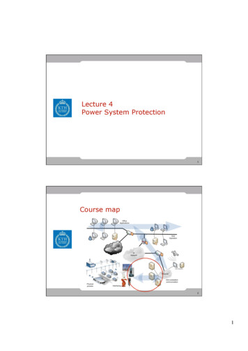
Energy balance theory (Cassie’s Theory):The space between the contacts contains some ionized gas immediately after current zeroand hence, it has a finite post –zero moment, power is zero because restriking voltage is zero.When the arc is finally extinguished, the power gain becomes zero, the gap is fully de-ionized andits resistance is infinitely high. In between these two limits, first the power increases, reaches amaximum value, then decreases and finitely reaches zero value as shown in figure. Due to the riseof restriking voltage and associated current, energy is generated in the space between the contacts.The energy appears in the form of heat. The circuit breaker is designed to remove this generatedheat as early as possible by cooling the gap, giving a blast air or flow of oil at high velocity andpressure. If the rate of removal of heat is faster than the rate of heat generation the arc isextinguished. If the rate of heat generation is more than the rate of heat dissipation, the spacebreaks down again resulting in an arc for another half cycle.Important Terms:The following are the important terms much used in the circuit breaker analysis:1. Arc Voltage:It is the voltage that appears across the contacts of the circuit breaker during the arcingperiod. As soon as the contacts of the circuit breaker separate, an arc is formed. The voltage thatappears across the contacts during arcing period is called the arc voltage. Its value is low exceptfor the period the fault current is at or near zero current point. At current zero, the arc voltage risesrapidly to peak value and this peak voltage tends to maintain the current flow in the form of arc.2. Restriking voltage:
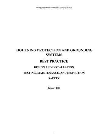
It is the transient voltage that appears across the contacts at or near current zero duringarcing period. At current zero, a high-frequency transient voltage appears across the contacts andis caused by the rapid distribution of energy between the magnetic and electric fields associatedwith the plant and transmission lines of the system. This transient voltage is known as restrikingvoltage (Fig. 19.1).The current interruption in the circuit depends upon this voltage. If the restriking voltagerises more rapidly than the dielectric strength of the medium between the contacts, the arc willpersist for another half-cycle. On the other hand, if the dielectric strength of the medium builds upmore rapidly than the restriking voltage, the arc fails to restrike and the current will be interrupted.3. Recovery voltage:It is the normal frequency (50 Hz) R.M.S. voltage that appears across the contacts of thecircuit breaker after final arc extinction. It is approximately equal to the system voltage.When contacts of circuit breaker are opened, current drops to zero after every half cycle.At some current zero, the contacts are separated sufficiently apart and dielectric strength of themedium between the contacts attains a high value due to the removal of ionized particles. At suchan instant, the medium between the contacts is strong enough to prevent the breakdown by therestriking voltage. Consequently, the final arc extinction takes place and circuit current isinterrupted. Immediately after final current interruption, the voltage that appears across thecontacts has a transient part (See Fig.19.1). However, these transient oscillations subside rapidlydue to the damping effect of system resistance and normal circuit voltage appears across thecontacts. The voltage across the contacts is of normal frequency and is known as recoveryvoltage.Expression for Restriking voltage and RRRV:The power system contains an appreciable amount of inductance and some capacitance.When a fault occurs, the energy stored in the system can be considerable. Interruption of faultcurrent by a circuit breaker will result in most of the stored energy dissipated within the circuitbreaker, the remainder being dissipated during oscillatory surges in the system. The oscillatorysurges are undesirable and, therefore, the circuit breaker must be designed to dissipate as much o fthe stored energy as possible.Fig. 19.17 (i) shows a short-circuit occurring on the transmission line. Fig 19.17 (ii) shows itsequivalent circuit where L is the inductance per phase of the system up to the point of fault and Cis the capacitance per phase of the system. The resistance of the system is neglected as it isgenerally small.Rate of rise of re-striking voltage:It is the rate of increase of re-striking voltage and is abbreviated by R.R.R.V. usually; thevoltage is in kV and time in microseconds so that R.R.R.V. is in kV/µ sec.Consider the opening of a circuit breaker under fault conditions Shown in simplified formin Fig. 19.17 (ii) above. Before current interruption, the capacitance C is short-circuited by thefault and the short-circuit current through the breaker is limited by Inductance L of the systemonly. Consequently, the short-circuit current will lag the voltage by 90º as shown in Fig. 19.18,where I Represents the short-circuit current and ea represents the arc voltage. It may be seen thatin this condition, the *entire generator voltage appears across inductance L.
When the contacts are opened and the arc finally extinguishes at some current zero, the generatorvoltage e is suddenly applied to the inductance and capacitance in series.Which appears across the capacitor C and hence across the contacts of the circuit breaker.This transient voltage, as already noted, is known as re-striking voltage and may reach aninstantaneous peak value twice the peak phase-neutral voltage i.e. 2 Em . The system losses causethe oscillations to decay fairly rapidly but the initial overshoot increases the possibility of restriking the arc.It is the rate of rise of re-striking voltage (R.R.R.V.) which decides whether the arc will restrike or not. If R.R.R.V. is greater than the rate of rise of dielectric strength between the contacts,the arc will re-strike. However, the arc will fail to re-strike if R.R.R.V. is less than the rate ofincrease of dielectric strength between the contacts of the breaker.The value of R.R.R.V. depends up on:1. Recovery voltage2. Natural frequency of oscillationsFor a short-circuit occurring near the power station bus-bars, C being small, the naturalfrequency fn will be high. Consequently, R.R.R.V. will attain a large value. Thus the worstcondition for a circuit breaker would be that when the fault takes place near the bus-bars.Current chopping:It is the phenomenon of current interruption before the natural current zero is reached.Current chopping mainly occurs in air-blast circuit breakers because they retain the sameextinguishing power irrespective of the magnitude of the current to be interrupted. When breakinglow currents (e.g., transformer magnetizing current) with such breakers, the powerful de-ionizingeffect of air-blast causes the current to fall abruptly to zero well before the natural current zero isreached. This phenomenon is known as current chopping and results in the production of highvoltage transient across the contacts of the circuit breaker as discussed below:Consider again Fig. 19.17 (ii) repeated as Fig. 19.19 (i). Suppose the arc current is i whenit is chopped down to zero value as shown by point a in Fig. 19.19 (ii). As the chop occurs atcurrent i, therefore, the energy stored in inductance is L i2 /2.This energy will be transferred to the capacitance C, charging the latter to a prospective voltage egiven by:The prospective voltage e is very high as compared to the dielectric strength gained by thegap so that the breaker restrike. As the de-ionizing force is still in action, therefore, chop occursagain but the arc current this time is smaller than the previous case. This induces a lowerprospective voltage to re-ignite the arc. In fact, several chops may occur until a low enoughcurrent is interrupted which produces insufficient induced voltage to re-strike across the breakergap. Consequently, the final interruption of current takes place.
Excessive voltage surges due to current chopping are prevented by shunting the contacts of thebreaker with a resistor (resistance switching) such that re ignition is unlikely to occur. This isexplained in Art 19.19.Capacitive current breaking:Another cause of excessive voltage surges in the circuit breakers is the interruption ofcapacitive currents. Examples of such instances are opening of an unloaded long transmissionline, disconnecting a capacitor bank used for power factor improvement etc. Consider the simpleequivalent circuit of an unloaded transmission line shown in Fig.19.20. Such a line, althoughunloaded in the normal sense, will actually carry a capacitive current I on account of appreciableamount of capacitance C between the line and the earth.Let us suppose that the line is opened by the circuit breaker at the instant when linecapacitive current is zero [point 1 in Fig. 19.21. At this instant, the generator voltage V g will bemaximum (i.e. V gm) lagging behind the current by 90º. The opening of the line leaves a standingcharge on it (i.e., end B of the line) and the capacitor C1 is charged to V gm. However, thegenerator end of the line (i.e., end A of the line) continues its normal sinusoidal variations. Thevoltage V r across the circuit breaker will be the difference between the voltages on the respectivesides. Its initial value is zero (point 1) and increases slowly in the beginning. But half a cycle later[point R in Fig. 19.21], the potential of the circuit breaker contact ‗A ‘ becomes maximumnegative which causes the voltage across the breaker (V r) to become 2 V gm. This voltage maybe sufficient to restrike the arc. The two previously separated parts of the circuit will now bejoined by an arc of very low resistance. The line capacitance discharges at once to reduce thevoltage across the circuit breaker, thus setting up high frequency transient. The peak value of theinitial transient will be twice the voltage at that instant i.e., 4 V gm. This will cause thetransmission voltage to swing to 4V gm to V gm i.e., 3V gm.The re-strike arc current quickly reaches its first zero as it varies at natural frequency. Thevoltage on the line is now 3 Vgm and once again the two halves of the circuit are separated andthe line is isolated at this potential. After about half a cycle further, the aforesaid events arerepeated even on more formidable scale and the line may be left with a potential of 5V gm aboveearth potential. Theoretically, this phenomenon may proceed infinitely increasing the voltage bysuccessive increment of 2 times V gm.While the above description relates to the worst possible conditions, it is obvious that ifthe gap breakdown strength does not increase rapidly enough, successive re-strikes can build up adangerous voltage in the open circuit line. However, due to leakage and corona loss, themaximum voltage on the line in such cases is limited to 5 V gm.Resistance Switching:It has been discussed above that current chopping, capacitive current breaking etc. giverise to severe voltage oscillations. These excessive voltage surges during circuit interruption canbe prevented by the use of shunt resistance R connected across the circuit breaker contacts as
shown in the equivalent circuit in Fig. 19.22. This is known as resistance switching.Referring to Fig. 19.22, when a fault occurs, the contacts of the circuit breaker are opened and anarc is struck between the contacts. Since the contacts are shunted by resistance R, a part of arccurrent flows through this resistance. This results in the decrease of arc current and an increase inthe rate of de-ionization of the arc path. Consequently, the arc resistance is increased. Theincreased arc resistance leads to a further increase in current through shunt resistance. Thisprocess continues until the arc current becomes so small that it fails to maintain the arc. Now, thearc is extinguished and circuit current is interrupted The shunt resistor also helps in limiting theoscillatory growth of re-striking voltage. It can be proved mathematically that natural frequencyof oscillations (or) the frequency of damped oscillation of the circuit shown in Fig. 19.22 is givenby:The effect of shunt resistance R is to prevent the oscillatory growth of re-striking voltageand cause it to grow exponentially up to recovery voltage. This is being most effective when thevalue of R is so chosen that the circuit is critically damped. The value of R required for criticaldamping is 0.5 . Fig. 19.23 shows the oscillatory growth and exponential growth when the circuitis critically damped.To sum up, resistors across breaker contacts may be used to perform one or more of the followingfunctions:1. To reduce the rate of rise of re-striking voltage and the peak value of re-striking voltage.2. To reduce the voltage surges due to current chopping and capacitive current breaking.3. To ensure even sharing of re-striking voltage transient across the various breaks in multibreak circuit breakers.It may be noted that value of resistance required to perform each function is usually different.However, it is often necessary to compromise and make one resistor do more than one of thesefunctions.Switchgear Components:The following are some important components common to most of the circuit breakers:1. Bushings2. Circuit breaker contacts3. Instrument transformers
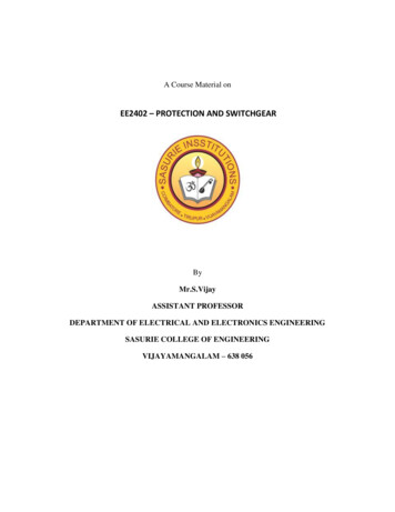
4. Bus-bars and conductorsBushings:When a high voltage conductor passes through a metal sheet or frame which is at earthpotential, the necessary insulation is provided in the form of bushing. The primary function of thebushing is to prevent electrical breakdown between the enclosed conductor and the surroundingearthed metal work. Fig. 19.13 (i) shows the use of bushing for a plain-break oil circuit breaker.The high voltage conductor passes through the bushing made of some insulating material (e.g.,porcelain, steatite). Although there are several types of bushing (e.g., condenser type, oil filledetc.), they perform the same function of insulating the conductor from earthed tank. The failure ofthe bushing can occur in two ways. Firstly, the breakdown may be caused by puncture i.e.,dielectric failure of the insulating material of the bushing. Secondly, the breakdown may occur inthe form of a flash-over between the exposed conductor at either end of the bushing and theearthed metal. Fig. 19.13 (ii) illustrates these two possibilities. The bushings are so designed thatflash-over takes place before they get punctured. It is because the puncture generally renders thebushing insulation unserviceable and incapable of withstanding the normal voltage. On the otherhand, a flash-over may result in comparatively harmless burning of the surface of the bushingwhich can then continue to give adequate service pending replacement.Circuit breaker contacts:The circuit breaker contacts are required to carry normal as well as short-circuit current. Incarrying the normal current, it is desirable that the temperature should not rise above the specifiedlimits and that there should be low voltage drop at the point of contact. In carrying breaking andmaking short-circuit currents, the chief effects to be dealt with are melting and Vaporization bythe heat of the arc and those due to electromagnetic forces. Therefore, the design of contacts is ofconsiderable importance for satisfactory operation of the circuit breakers. There are three types ofcircuit breaker contacts viz.
a. Tulip type contacts: Fig. 19.14 (i) shows the Tulip type contact. It consists of movingcontact which moves inside the fixed contacts. At contact separation, the arc is generallyestablished between the tips of the fixed contacts and the tip of the moving contact asshown in Fig. 19.14 (ii). The advantage of this type of contact is that arcing is confined tothe regions which are not in contact in the fully engaged position.b.Finger and wedge contacts: Fig. 19.15 (i) shows the finger and wedge type contact.This type of contact iis largely used for low-voltage oil circuit breakers owing to thegeneral unsuitability for use with arc control devices.c. Butt contacts: Fig. 19.15 (ii) shows the butt type contact and is formed by the springsand the moving contact. It possesses two advantages. Firstly, spring pressure is availableto assist contact separation. This is useful in single-break oil circuit breakers and air-blastcircuit breakers where relatively small ―loop‖ forces are available to assist in opening.Secondly, there is no grip force so that this type of contact is especially suitable for highershort circuit rating.Instrument transformers:In a modern power system, the circuits operate at very high voltages and carry current ofthousands of amperes. The measuring instruments and protective devices cannot worksatisfactorily if mounted directly on the power lines. This difficulty is overcome by installinginstrument transformers on the power lines. The function of these instrument transformers is totransform voltages or currents in the power lines to values which are convenient for the operationof measuring instruments and relays.
There are two types of instrument transformers viz.1. Current transformer (C.T.)2. Potential transformer (P.T.)The primary of current transformer is connected in the power line. The secondary windingprovides for the instruments and relays a current which is a constant fraction of the current in theline similarly, a potential transformer is connected with its primary in the power line. Thesecondary provides for the instruments and relays a voltage which is a known fraction of the linevoltage. Fig. 19.16 shows the use of instrument transformers. The *potential transformer rated66,000/110V provides a voltage supply for the potential coils of voltmeter and wattmeter. Thecurrent transformer rated 1000/5 A supplies current to the current coils of wattmeter and ammeter.The use of instrument transformers permits the following advantages:a. They isolate the measuring instruments and relays from high-voltage power circuits.b. The leads in the secondary circuits carry relatively small voltages and currents. Thispermits to use wires of smaller size with minimum insulation.Bus-bars and conductors: The current carrying members in a circuit breaker consist of fixed andmoving contacts and the conductors connecting these to the points external to the breaker. If theswitchgear is of outdoor type, these connections are connected directly to the overhead lines. Incase of indoor switchgear, the incoming conductors to the circuit breaker are connected to the busbars.Circuit Breaker Ratings:A circuit breaker may be called upon to operate under all conditions. However, majorduties are imposed on the circuit breaker when there is a fault on the system in which it isconnected. Under fault conditions, a circuit breaker is required to perform the following threeduties:i.It must be capable of opening the faulty circuit and breaking the fault current.ii.It must be capable of being closed on to a fault.iii.It must be capable of carrying fault current for a short time while another circuit breaker(in series) is clearing the fault.Corresponding to the above mentioned duties, the circuit breakers have three ratings viz.1. Breaking capacity2. Making capacity and3. Short-time capacity.Breaking capacity: It is current (r.m.s.) that a circuit breaker is capable of breaking at givenrecovery voltage and under specified conditions (e.g., power factor, rate of rise of restrikingvoltage).The breaking capacity is always stated at the r.m.s. value of fault Current at the instant ofcontact separation. When a fault occurs, there is considerable asymmetry in the fault current dueto the Presence of a d.c. component. The d.c. component dies away rapidly, a typical decrementfactor being 0·8 per cycle. Referring to Fig. 19.24, the contacts are separated at DD At thisinstant, the fault current has
x maximum value of a.c. component y d.c. componentSymmetrical breaking current r.m.s. value of a.c. componentAsymmetrical breaking current r.m.s. value of total currentIt is a common practice to express the breaking capacity in MVA by taking into accountthe rated breaking current and rated service voltage. Thus, if I is the rated breaking current inamperes and V is the rated service line voltage in volts, then for a 3-phase circuit,In India (or Britain), it is a usual practice to take breaking current equal to the symmetricalbreaking current. However, American practice is to take breaking current equal to asymmetricalbreaking current. Thus the American rating given to a circuit breaker is higher than the Indian orBritish rating.It seems to be illogical to give breaking capacity in MVA since it is obtained from theproduct of Short-circuit current and rated service voltage. When the short-circuit current isflowing, there is only a small voltage across the breaker contacts, while the service voltageappears across the contacts only after the current has been interrupted. Thus MVA rating is theproduct of two quantities which do not exist simultaneousl
protection of distribution transformers,lighting circuits, branch circuits of distribution lines etc. 4. With the advancement of power system, the lines and other equipment operate at very high voltages and carry large currents. The arrangement of switches along with fuses cannot serve th