Transcription
Class Notes ofBET102 Basic Electronics EngineeringCommon to 1st /2nd SemesterofDiploma in Engineering.Under SCTE&VT , Odisha.Prepared By:Rajendra Kumar PrustyAsima RoutSarat Kumar Muduli
BET-102Basic Electronics Engineering.Chapter-11. ELECTRONIC DEVICES1.1Define Electronics & its application.The world's reliance on electronics is so great that commentators claim people live in an"electronic age." People are surrounded by electronics—televisions, radios, computers, mobiles,Laptop and DVD players, along with products with major electric components, such asmicrowave ovens, refrigerators, and other kitchen appliances, automatic vehicles, Robotics, aswell as hearing aids and medical instruments and numerous applications in industry.Definition: The branch of engineering which deals with current conduction through a Vacuumor Gas or Semiconductor is known as Electronics. An electronic device is that in which currentflows through a vacuum or gas or semiconductor. This control of electrons is accomplished bydevices that resist, carry, select, steer, switch, store, manipulate, and exploit the electron.OrElectronics deals with electrical circuits that involve active electrical components such asvacuum tubes, transistors, diodes and integrated circuits, and associated passiveinterconnection technologies. Commonly, electronic devices contain circuitry consistingprimarily or exclusively of active semiconductors supplemented with passive elements; such acircuit is described as an electronic circuit.Pre Knowledge (Some of the basic definitions):Passive Components: Capable of operating without an external power source. Typical passivecomponents are resistors, capacitors, inductors.Active components: Requiring a source of power to operate. Includes transistors (all types), integratedcircuits (all types), TRIACs, SCRs, LEDs, etc.APPLICATIONS of Electronics:Electronic components: capacitor (C), cathode ray tube (CTR), diode (D), digital signalprocessor (DSP, field effect transistor (FET), integrated circuit (IC), junction gate field effecttransistor (JFET), inductor (L), Liquid crystal display (LCD), light dependent resistor (LDR, lightemitting diode (LED), Metal oxide semiconductor field effect transistor (MOSFET), transistor(Q), resistor (R), relay (RLA, RY), switch (SW), transformer (T), thermistor (TH), transistor(Tr), integrated circuit (U, IC), variable capacitor (VC), variable resistor (VR) and more.Consumer Electronics include products like – Audio Systems, Video Systems, TV (Television),Computer, Laptop, Digital Camera, DVD Players, Home and Kitchen Appliances, GPS, MobilesPhones etc.
Communication. Electronic communication systems connect people around the world. Usingtelephones, Internet and computers, people in different countries communicate almostinstantly. Radios transmit sounds and televisions transmit sounds and pictures great distances.Cellular telephones enable a person to call another person. Within seconds, fax machines sendand receive copies of documents over telephone lines/Satellite.Information processing. Scientists, artists, students, government and business workers, andhobbyists at home all rely on computers, Internet to handle huge amounts of informationquickly and accurately. Computers solve difficult mathematical problems, maintain vastamounts of data, create complex simulations, and perform a multitude of other tasks that helppeople in their everyday lives.Medicine and research. Include product like X-ray machines ECG (Electrocardiogram) useradiation to take images of bones and internal organs. Radiation therapy, or radiotherapy, usesX-rays and other forms of radiation to fight cancer. Many hearing-impaired people depend onhearing aids to electrically amplify sound waves.Computers and other electronic instruments provide scientists and other researchers withpowerful tools to better understand their area of study. Computers, for example, help scientistsdesign new drug molecules, track weather systems, and test theories about how galaxies andstars develop. Electron microscopes use electrons rather than visible light to magnify specimens1 million times or more.Automation. Electronic components enable many common home appliances, such asrefrigerators, washing machines, and toasters, to function smoothly and efficiently. People canelectronically program coffeemakers, lawn sprinklers, and many other products to turn on andoff automatically. Microwave ovens heat food quickly by penetrating it with short radio wavesproduced by a vacuum tube.Instrumentation. Measuring Instruments like CRO, Multimeter, ph-meter, strain gauge,VTVM, Frequency Counter are used in different Laboratory/organisations.Many automobiles have electronic controls in their engines and fuel systems. Electronic devicesalso control air bags, which inflate to protect a driver and passengers in a collision.1.2 Define Electronic Emission & different types of Emission.The Electronics devices depends the movements of free Electrons in an evacuated space.The liberation of electrons from the surface of a metal is known as Electron Emission. For electron emission, metals are used because they have many free electrons.The electrons are free only to transfer from one atom to another within the metal butthey cannot leave the metal surface to provide electron emission.Thus at the surface of the metal, a free electron encounters forces that prevent it toleave the metal.In other words, the metallic surface offer a barrier to free electrons, their kineticenergy increases and is known as surface barrier.However, if sufficient energy is given to the free electrons, their kinetic energyincreases and thus the electrons will cross over the surface barrier to leave the metal.This additional energy required by an electron to overcome the surface barrier of themetal is called work function of the metal.
The metallic surface offers a barrier to free electrons and is known as surface barrier.Work function (W0): The amount of additional energy(such as heat energy, energy stored inelectric field, light energy or kinetic energy of the electric charges bombarding the metalsurface) required to emit an electron from a metallic surface is known as work function of thatmetal. The minimum energy required by an electron to just escape (i.e. with zero velocity) frommetal's surface is called Work function (W0) of the metal. The work function of pure metalsvaries (roughly) from 2eV to 6eV. Its value depends upon the nature of the metal, its purityand the conditions of the surface.Different types of Emission:There are following four principal method of obtaining electron emission from the surface of ametal:1. Thermionic Emission(Due to Thermal energy)2. Field Emission(Due to application of strong electric field)3. Secondary Emission–( due to bombardment of high-speed electrons)4. Photo Electric Emission–( by the application of light)1. Thermionic EmissionThe process of electron emission from a metal surface by supplying thermal energy to it isknown as Thermionic emission.In this type of emission the electron emission is achieved by heating the electrode to asufficient temperature (about 2500oC) to enable the free electrons to leave the metal surface.Due to heating the electrons get enough energy that they emit from the surface of that materialheat energy is converted into kinetic energy, causing accelerated motion of free electrons andelectrons acquire additional energy equal to the work function of the metal. An electron emittedfrom a hot cathode comes out with a velocity that presents different between the kinetic energypossessed by electron just before emission usually used in cathode of diode, triode, pentode,CRT and many other. The higher the temperature, the greater is the emission of electrons. Thecommonly used materials for electron emission are tungsten, thoriated tungsten and metallicoxides of barium and strontium.S.No.123EmitterTungstenThoriated tungstenOxide-coatedWork FunctionOperating Temperature4.52 eV2.63 eV1.1 eV2327ºC1700ºC750ºC2. Field EmissionThe process of electron emission by the application of strong electric field at the surface of ametal is known as field emission.When metal surface is placed in an electric field, the electron rotating in their orbitsexperience a force due to electrostatic field. Hence the process of electron emission byapplication of strong electric field at the surface of a metal is called field emission. It is alsocalled cold cathode emission or auto- electronic emission.
3. Secondary EmissionElectron emission from a metallic surface by the bombardment of high-speed electronsor other particles is known as secondary emission.When high-speed electrons suddenly strike a metallic surface, they may give some or allof their kinetic energy to the free electrons in the metal. If the energy of the strikingelectrons is sufficient, it may cause free electrons to escape from the metal surface. Thisphenomenon is called secondary emission. The electrons that strike the metal are calledprimary electrons while the emitted electrons are known as secondary electrons. Theintensity of secondary emission depends upon the emitter material, mass and energy of thebombarding particles.4. Photo Electric EmissionElectron emission from a metallic surface by the application of light is known as photoelectric emission.When a beam of light strikes the surface of cathode normally made of potassium, Sodium theenergy of photons of light is transfer to the free electrons of cathode. In this method, theenergy of light falling upon the metal surface is transferred to the free electrons within themetal to enable them to leave the surface. The greater the intensity of light beam falling on themetal surface, the greater is the photoelectric emission. The emitted electrons are known asphoto electrons and the phenomenon is known as photoelectric emission. Photo-electricemission is utilised in photo tubes which form the basis of television and sound films.1.3 Classification of solid according to electrical conductivity (Conductor, Semiconductor &Insulator) with respect to energy band diagram only.Pre-Knowledge:(i) Valence band. The range of energies (i.e. band) possessed by valence electrons isknown as valence band. The electrons in the outermost orbit of an atom are known asvalence electrons. This band may be completely or partially filled.(ii) Conduction band.The range of energies (i.e. band) possessed by conduction band electrons is known asconduction band.Generally, insulators have empty conduction band. On the otherhand, it is partially filled for conductors. The free electrons which are responsible for theconduction of current in a conductor are called conduction electrons.(iii) Forbidden energy gap. The separation between conduction band and valenceband on the energy level diagram is known as forbidden energy gap.
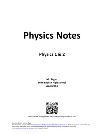
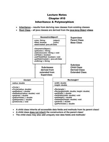
Fig 1. Energy band diagramClassification:Solid-state materials According to electrical conductivity can be classified into threegroups. Such as:1. Insulators - Insulators are materials having an electrical conductivity(like diamond: 10-14S/cm);2. Semiconductors - semiconductors have a conductivitysilicon it can range from 10-5S/cm to 103S/cm)(for3. Conductors - at last conductors are materials with high conductivities:(like silver: 106S/cm.)Figure 2 : Representation of energy bands(i) Insulators. Insulators (e.g. wood, glass, plastics,rubber etc.) are those substances which donot allow the passage of electric current through them. In terms of energy band, thevalence band is full while the conduction band is empty as shown in Fig 2. Further, theenergy gap between valence and conduction bands is very large (15 eV). Therefore, a veryhigh electric field is required to push the valence electrons to the conduction band. For thisreason, the electrical conductivity of such materials is extremely small. At room
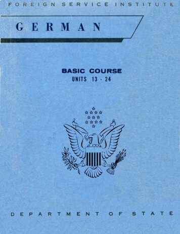
temperature, the valence electrons of the insulators do not have enough energy to crossover to the conduction band. However, when the temperature is raised, some of thevalence electrons may acquire enough energy to cross over to the conduction band. Hence,the resistance of an insulator decreases with the increase in temperature i.e. an insulatorhas negative temperature coefficient of resistance.(ii) Conductors. Conductors (e.g. copper, aluminum) are those substances which easily allowthe passage of electric current through them. It is because there are a large number of freeelectrons available in a conductor. In terms of energy band as in Fig 2, the valence andconduction bands overlap each other due to this overlapping; a slight potential differenceacross a conductor causes the free electrons to constitute electric current.(iii) Semicondutors.Semiconductors (e.g. germanium, silicon etc.) are those substanceswhose electrical conductivity lies in between conductors and insulators. In terms of energyband, the valence band is almost filled and conduction band is almost empty in fig 2.Further, the energy gap between valence and conduction bands is very small. Thesemiconductor has :(a) Filled valence band(b) Empty conduction band(c) Small energy gap or forbidden gap ( 1 eV) between valence and conduction bands.(d) Semiconductor virtually behaves as an insulator at low temperatures. However, even atroom temperature, some electrons cross over to the conduction band, imparting littleconductivity (i.e. conductor).1.3Discuss Intrinsic & Extrinsic Semiconductor.Intrinsic SemiconductorA semiconductor in an extremely pure form is known as an intrinsic semiconductor.In this case the holes in the valence band are vacancies created by electrons that have beenthermally excited to the conduction band and hole-electron pairs are created. When electricfield is applied across an intrinsic semiconductor, the current conduction takes place by twoprocesses, namely; by free electrons and holes as shown in Fig 3. The free electrons areproduced due to the breaking up of some covalent bonds by thermal energy. At the same time,holes are created in the covalent bonds. Under the influence of electric field, conductionthrough the semiconductor is by both free electrons and holes. Therefore, the total currentinside the semiconductor is the sum of currents due to free electrons and holes. This createsnew holes near the positive terminal which again drift towards the negative terminal.Figure 3 : Diagram showing the electronic bonds in an intrinsic semiconductor (Si)Extrinsic SemiconductorAn extrinsic semiconductor is a semiconductor doped by addition of small amountimpurity which is able to change its electrical properties (conduction), making it suitable forelectronic applications (diodes, transistors, etc.) or optoelectronic applications (light emittersand detectors). This is achieved by adding a small amount of suitable impurity (having 3 or 5valence electron) to a semiconductor (having 4 valence electron). It is then called impurity orextrinsic semiconductor.
The process of adding impurities to a semiconductor is known as doping. The purpose ofadding impurity is to increase either the number of free electrons or holes in thesemiconductor crystal.If a penta valent impurity (having 5 valence electrons) is added to the semiconductor, alarge number of free electrons are produced in the semiconductor.If a trivalent impurity (having 3 valence electrons) is added to the semiconductor, largenumber of holes are produced in the semiconductor crystal.Depending upon the type of impurity added, extrinsic semiconductors are classified into:(i)n-type semiconductor(ii) p-type semiconductor(i)n-type SemiconductorWhen a small amount of pentavalent impurity is added to a pure semiconductor, it is known as n-typesemiconductor.The addition of pentavalent impurity pro-vides a large number of free electrons in thesemiconductor crystal. Typical examples of pentavalent impurities are arsenic ,antimony,Bismuth and Phosphorous etc. Such impurities which produce n-type semiconductorare known as donor impurities because they donate or provide free electrons to thesemiconductor crystal.Figure 4 : Schematic representation of electronic bonds in a Silicon crystal doped with Arsenic As (ndoping) (ii)Electrons are said to be the majority carriers whereas holes are the minority carriers.p-type SemiconductorWhen a small amount of trivalent impurity is added to a pure semiconductor, it is called p-typeSemiconductor.The addition of trivalent impurity provides a large number of holes in the semiconductor.Typical examples of trivalent impurities are gallium , indium, boron etc. Such impurities whichproduce p-type semiconductor are known as acceptor impurities because the holes created canaccept the electrons fig 5.Figure 5 : schematic representation of a Si crystal doped with boron (B)Electrons are said to be the minority carriers whereas holes are the majority carriers.
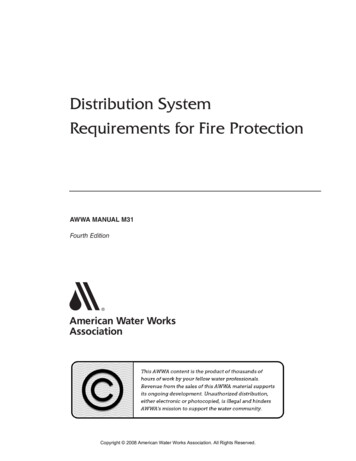
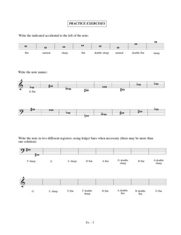
1.4Explain the difference between vacuum tube & semiconductor.Figure 6: Vacuum tubesVacuum Tubes:Advantages1. Superior sound quality.2. Can handle large currents3. Tolerant of large overloads and voltage spikes.4. Characteristics highly independent of temperature, greatly simplifying biasing.5. Wider dynamic range than transistors circuits, due to higher operating voltages andoverload tolerance.6. Capacitive coupling can be done with small, high-quality film capacitors, due toinherently high-impedances of tube circuits.7. Operation is usually in Class A or Class AB, minimizing crossover notch distortion.8. Tubes can be relatively easily replaced by user.Disadvantages1. Bulky(Larger in Size), hence not suitable for portable products2. Higher operating voltages required.3. High power consumption; needs heater supply that generates waste heat and yieldslower efficiency, notably for small-signal circuits.4. Glass tubes are fragile, compared to metal transistors.5. Cathode electron-emitting materials are used up in operation.6. High-impedance devices that need impedance matching transformer for low-impedanceloads, like speakers; however, the magnetic cushion provided by an output transformerprevents the output tubes from blowing up.7. Sometimes higher cost than equivalently powered transistors.8. Complicated in manufacturing process.Transistors:Advantages1. Usually smaller size, lower cost and longer life.2. Can handle small current3. Can be combined in the millions on one cheap die to make an integrated circuit, whereastubes are limited to at most three functional units per glass bulb.4. Lower power consumption, less waste heat, and high efficiency than equivalent tubes,especially in small-signal circuits.5. Can operate on lower-voltage supplies for greater safety, lower costs, tighter clearances.6. Usually more physical ruggedness than tubes (depends upon construction).Disadvantages1. Tendency toward higher distortion2. Complex circuits and considerable negative feedback required for low distortion.3. Large unit-to-unit manufacturing tolerances and unreliable variations in key parameters,such as gain and threshold voltage.4. Device parameters vary considerably with temperature, complicating biasing andincreasing likelihood of thermal runaway.5. Cooling is less efficient than with tubes, because lower operating temperature is requiredfor reliability. Tubes prefer hot; transistors do not. Massive, expensive and unwieldyheat sinks are always required for power transistors, yet they are not always effective
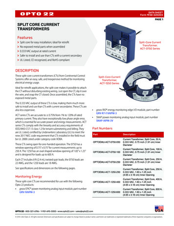
6.7.8.9.1.5(power output transistors still blow up; whereas, tubes fade down gracefully over timewith warning.)Less tolerant of overloads and voltage spikes than tubes.Capacitive coupling usually requires high-value electrolytic capacitors, which give audiblyand measurably inferior performance at audio frequency extremes.Greater tendency to pick up radio frequency interference and self-oscillate to the pointof self-destruction, due to rectification by low-voltage diode junctions or slew-rateeffects.Maintenance more difficult; devices are not easily replaced by user.State basic concept of Integrated Circuits (I.C) & its use.Figure 7: Integrated CircuitsAn integrated circuit (IC), sometimes called a chip or microchip, is a semiconductor wafer onwhich thousands or millions of tiny resistors, capacitors, and transistors are fabricated. An ICcan function as an amplifier, oscillator, timer, counter, computer memory, or microprocessor. Aparticular IC is categorized as either linear analog or digital, depending on its intendedapplication. IC's are are of Linear , digital and mixed typesLinear ICs have continuously variable output (theoretically capable of attaining an infinitenumber of states) that depends on the input signal level. As the term implies, the output signallevel is a linear function of the input signal level. Linear ICs are used as audio-frequency (AF)and radio-frequency (RF) amplifiers. The operational amplifier (op amp) is a common device inthese applications.Digital ICs operate at only a few defined levels or states, rather than over a continuous range ofsignal amplitudes. These devices are used in computers, computer networks, modems, andfrequency counters. The fundamental building blocks of digital ICs are logic gates, which workwith binary data, that is, signals that have only two different states, called low (logic 0) andhigh (logic 1).Applications and Uses of Integrated CircuitsThe advantages of Integrated Circuits are:1. Very small size: Hundred times smaller than the discrete circuits.2. Lesser weight: As large number of components can be packed into a single chip, weight is reduced3. Reduced cost: The mass production technique has helped to reduce the price,4. High reliability: Due to absence of soldered connection, few interconnections and small temperaturerise failure rate is low.5. Low power requirement: As the size is small power consumption is less.6. Easy replacement: In case of failure chip can easily be replaced.Linear IC's also known as analog Integrated circuits are:1. Power amplifiers2. Small-signal amplifiers3. Operational amplifiers4. Microwave amplifiers5. RF and IF amplifiers6. Voltage comparators
7. Multipliers8. Radio receivers9. Voltage regulatorsDigital IC's are mostly used in computers. They are also referred as switching circuits because their input andoutput voltages are limited to two levels - high and low i.e. binary. They include:1. Flip-flops2. Logic gates3. Timers4. Counters5. Multiplexers6. Calculator chips7. Memory chips8. Clock chips9. Microprocessors10. Microcontrollers11. Temperature sensorsMixed type applications - cars (automotive controls), televisions, computers, microwaves,portable devices like laptops, MP3, play stations, cameras, cellular phones to ship equipments,aero planes, space craft’s. These are also used in switching telephone circuits and dataprocessing. They also found applications in military equipments. The most common applicationof IC is digital watch which tells hour, second, minute, day and month. Another common butimportant application is scientific calculator which can perform basic functions like addition,subtraction, multiplication and division as well as complex functions like square root, cube,permutations, combinations , trigonometric functions, etcChapter Review Questions:1.2.3.4.Define Electronics & its application.Define work function.Define Electronic Emission & different types of Emission.Explain Conductor, Semiconductor & Insulator with respect to energy banddiagram only.5. Define doping.6. Define energy gap & valence electrons7. Discuss Intrinsic Semiconductor.8. Discuss Extrinsic Semiconductor.9. Explain the difference between vacuum tube & semiconductor.10. State basic concept of integrated circuits (I.C) & its use.11. Define accepter & donor atom12. List different types of Impurity.
Chapter-22.1 Define Rectifier & state its use.The conversion of bidirectional alternating current (a.c.) into unidirectional direct current (d.c.)is called rectification. Electronic devices can convert a.c. power into d.c. power with very highefficiency.Example-Diodes : Diodes are useful electrical components for rectification purposes. Diodes areused in many applications like the following. 2.1.1Converting AC power from the 60Hz line into DC power for radios, televisions, telephoneanswering machines, computers, and many other electronic devices.Converting radio frequency signals into audible signals in radios.used as rectifier in DC Power Supplies.In Demodulation or Detector Circuits.In clamping networks used as DC RestorersIn clipping circuits used for waveform generation.As switches in digital logic circuitRectifying diodeReview of P-type and N-type semiconductor junction of P-type & N-type i.e. PN junction Barriervoltage, depletion region, Junction Capacitance.A p–n junction is a boundary or interface between two types of semiconductor material,p-type and n-type, inside a single crystal of semiconductor. p–n junctions areelementary "building blocks" of most semiconductor electronic devices such asdiodes, transistors, solar cells, LEDs, and integrated circuits. After joining p-typeand n-type semiconductors, electrons from the n region near the p–n interface tend todiffuse into the p region. The regions nearby the p–n interfaces lose their neutrality andbecome charged, forming the space charge region or depletion layer
Fig 8 (a) Blocks of P and N semiconductor in contact have no exploitable properties. (b) Singlecrystal doped with P and N type impurities develops a potential barrier.This separation of charges at the PN junction constitutes a potential barrier. This potentialbarrier must be overcome by an external voltage source to make the junction conduct.PN Junction DiodesExample:Circuit symbol:FunctionDiodes allow electricity to flow in only one direction. The arrow of the circuit symbol shows thedirection in which the current can flow.Forward Voltage DropWhen a forward voltage is applied to diode, a small voltageexperiences across a conducting diode, it is called theforward voltage drop and is about 0.7V for all normaldiodes which are made from silicon. The forward voltage dropof a diode is almost constant whatever the current passingthrough the diode so they have a very steep characteristic(current-voltage graph).Reverse VoltageWhen a reverse voltage is applied a perfect diode does not conduct, but all real diodes leak a verytiny current of a few µA or less. This can be ignored in most circuits because it will be very muchsmaller than the current flowing in the forward direction. However, all diodes have a maximumreverse voltage (usually 50V or more) and if this is exceeded the diode will fail and pass a largecurrent in the reverse direction, this is called breakdown.Ordinary diodes can be split into two types: Signal diodes which pass small currents of 100mAor less and Rectifier diodes which can pass large currents. In addition there are other types ofdiodes as such : LEDs, Zener diodes ,Tunnel diode,PIN diode,Photo diode and Varicap diode etc.
Practical Knowledge:Connecting and solderingDiodes must be connected the correct way round, the diagram maybe labeled a or for anode and k or - for cathode (yes, it really isk, not c, for cathode!). The cathode is marked by a line painted onthe body. Diodes are labeled with their code in small print, youmay need a magnifying glass to read this on small signal diodes!Small signal diodes can be damaged by heat when soldering, butthe risk is small unless you are using a germanium diode (codes beginning OA.) in whichcase you should use a heat sink clipped to the lead between the joint and the diode body. Astandard crocodile clip can be used as a heat sink.Signal diodes (small current)Signal diodes are used to process information (electrical signals) in circuits, so they are onlyrequired to pass small currents of up to 100mA.General purpose signal diodes such as the 1N4148 are made from silicon and have a forwardvoltage drop of 0.7V.Germanium diodes such as the OA90 have a lower forward voltage drop of 0.2V and thismakes them suitable to use in radio circuits as detectors which extract the audio signal fromthe weak radio signal.For general use, where the size of the forward voltage drop is less important, silicon diodes arebetter because they are less easily damaged by heat when soldering, they have a lowerresistance when conducting, and they have very low leakage currents when a reverse voltage isapplied.Biasing of Diode:The process of applying an external voltage is called as “biasing”.Pre Knowledge:Zero Bias: When no external voltage potential is applied to the PN junction diode called ZeroBiased Junction Diode. However if the diodes terminals are shorted together, a few holes(majority carriers) in the P-type material with enough energy to overcome the potential barrierwill move across the junction against this barrier potential. This is known as the “ForwardCurrent” and is referenced as IF. Likewise, holes generated in the N-type material (minoritycarriers) and move across the junction in the opposite direction. This is known as the “ReverseCurrent” and is referenced as IR. This transfer of electrons and holes back and forth across thePN junction is known as diffusion, as shown Fig 9.Fig 9: Zero Bias
But how ever there aretwo ways in which we can bias a pn junction diode.1) Forward bias2) Reverse biasForward Bias – The voltage potential is connected positive, ( ve) to the P-type material and negative, (-ve)to the N-type material across the diode which has the effect of Decreasing the PN junction diodes’s width.Reverse Bias – The voltage potential is connected negative, (-ve) to the P-type material and positive, ( ve) tothe N-type material across the diode which has the effect of Increasing the PN junction diode’s width.2.1.2 Forward & Reverse bias & V-I characteristics of PN junction DiodeForward Biased PN Junction DiodeWhen a diode is connected in a Forward Bias condition, a n
Pre Knowledge (Some of the basic definitions): Passive Components: Capable of operating without an external power source. Typical passive components are resistors, capacitors, inductors. Active components: Requiring a source of power to operate. Includes transistors (all types), integrated