Transcription
FLUORESCENT EMERGENCY BALLAST750 LUMENS4-PIN COMPACT FLUORESCENT LAMPSINSTALLATION INSTRUCTIONSWhen using this lighting devicesafety precautions should be followed at all timesPLEASE READ CAREFULLY AND FOLLOW ALLINSTRUCTIONS FOR YOUR OWN SAFETY1. Prior to installation, battery connector must be open to prevent highvoltage from being present on out put leads (red & yellow). It must beconnected only after installation is complete and A.C. Power is suppliedto the unit.2. This unit can operate commonly used linear and compact fluorescentlamps. Please refer to the “lamps list” label on the ballast for specificlamp information.3. Please ensure the electricity connections conform to the NationalElectrical Code and local regulations if applicable.4. To avoid electric shock, please disconnect normal and emergencypower supplies, and battery connector of the emergency ballast beforeservicing.5. This device is designed for factory or field installation in either theballast channel, or on top of the fixture, except air handling heatedair outlets, sealed and gasketed fixtures, wet or hazardous locationfixtures. Do not install this device near gas or electric heaters.6. AC power source of 120 VAC or 277 VAC is required.7. The battery is sealed, no-maintenance, and is not replaceable in thefield. Please contact manufacturer for information on service. Do notattempt to service the battery.8. Do not use accessory equipment that is not recommended bymanufacturer. Failure to do so may cause unsafe conditions. Servicingshould only be performed by qualified service personnel.9. Do not use the product for other than it's intended purpose.CAUTION: Verify that all replacement lamp types marked on the installedluminaire are also identified as suitable for use with this inverter/charger pack.PLEASE SAVE THESE INSTRUCTIONS
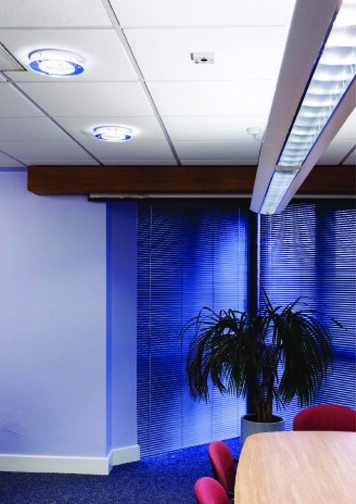
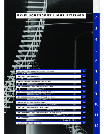
INSTALLATION INSTRUCTIONSCAUTION: Before installing, make certain the A.C. power is off and theEMERGENCY BALLAST' S unit connector is disconnected.1. MOUNTING THE EMERGENCY BALLAST(BATTERY PACK)When used with ceiling mounted downlight fixtures, the EMERGENCY BALLAST should be mounted on the fixtureabove the ceiling. The flex conduit marked " A" should be wired into the ballast/lamp compartment or to an electricaljunction box on the fixture which allows access to the ballast/lamp connection. Refer to lllustration 1 for typical mounting.lllustration 1Downlight FixtureBAL650C-4ACEMERGENCY BALLASTFLEX “A”A.C.BALLAST&A.C.BALLAST &LAMP SOCKET COMPARTMENTFLEX “B”JUNCTIONBOXSWITCH BOXTEST SWITCHCEILINGTILELCTSCHARGE LIGHTWhen battery packs are remote mounted, the remote distance cannot exceed 1/ 2 of the distance from ballast tolamp(s) specified by the A.C. ballast manufacturer. Under no circumstances should the battery pack exceed a distance 10' from the lamp.2. INSTALLING THE LED COMBO TEST SWITCH(LCTS)Cut the single gang switch box into the ceiling tile adjacent to the fixture within reach of the EMERGENCY BALLASTflex marked "B". After mounting the switch box, connect flex "B" to the box and route all leads inside the box.Refer to lllustration 1 for typical mounting.3. WIRINGA. The EMERGENCY BALLAST and A.C. Ballast must be on the same branch circuit.B. This EMERGENCY BALLAST requires an unswitched A.C. Power source of either 120 or 277 volts; therefore,when used with switched fixtures, input to the EMERGENCY BALLAST must be wired ahead of the switch.Refer to lllustration 2 for switched and unswitched fixture wiring diagrams.C. Refer to the wiring diagrams on the back page for proper wiring. For wiring diagrams of ballasts notshown, consult our customer service.lllustration 2Switched FixtureUnswitched FixtureBLACKBLACKWHITEA.C.BALLASTWHITEHOT A.C.LINEA.C.BALLASTHOT A.C.LINEWHT/BLKWHT/BLKWHITECOMMON(277V) ORG1LCTS1(120V)BLKBROWN(-)BROWN(-)VIOLET( )VIOLET( )WHITECOMMON(277V) ORGEMERGENCYBALLAST1LCTSBROWN(-)VIOLET( )Select proper voltage lead.Cap unused lead.1(120V)BLKEMERGENCYBALLASTBROWN(-)VIOLET( )Select proper voltage lead.Cap unused lead.4. LABELSAttach the appropriate labels adjacent to the LCTS. Annotate Re-lamping label for lamp type and wattage. The'Caution' and the 'Re-lamping' labels must be on the fixture in a readily visible location to anyone attempting toservice the fixture.INSURE WIRING IS IN ACCORDANCE WITH NATIONAL ELECTRICAL CODE AND LOCAL REGULATIONS.Page 2
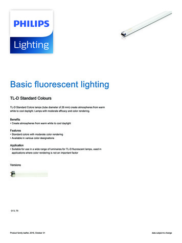
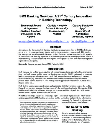
5. COMPLETING INSTALLATIONWhen the installation is complete, switch the A.C. power ON and join the EMERGENCY BALLAST' S unit connector.OPERATIONGeneral-This unit is primarly designed to be used with compact fluorescent lamp downlight fixtures. It will wire in conjunction with the existing A.C. Ballast(s) and lamp(s) to provide the emergency function. It can also be wired foremergency only operation.Normal Mode - A.C. power is present. The A.C. ballast operates the fluorescent lamp(s) as intended. The LCTS will belit providing a visual indication that the EMERGENCY BALLAST is in the standby charging mode.Emergency Mode - The A.C. power fails. The EMERGENCY BALLAST senses the A.C. power failure and automaticallyswitches to the Emergency Mode. One or two lamps illuminate, at reduced output, for a minimum of 90 minutes. Whenthe A.C. Power is restored, the EMERGENCY BALLAST switches the system back to the Normal Mode and resumesbattery charging.TESTING & MAINTENANCEPressing the red lens on the LCTS turns off the light on the LCTS and forces the unit into emergency mode. Thisinterrupts power to the emergency lamps only. The emergency lamp is now being lit by the EMERGENCY BALLAST unit andwill be less bright than the other lamps in the system. To simulate a “BLACK OUT”use the circuit breaker to turn off A.C. Power.Initial Testing - Allow the unit to charge for approximately 1 hour, then press the LCTS to conduct a short discharge test.Allow a 24 hour charge before conducting a 11/ 2 hour test.This EMERGENCY BALLAST is a maintenance free unit, however, periodic inspection and testing is required. NFPA 101,Life Safety Code, outlines the following schedule:Monthly - Insure that the LCTS is illuminated. Conduct a 30 second discharge test by depressing the LCTS. Oneor two lamps should operate at reduced output.Annually - Insure that the LCTS is illuminated. Conduct a full 11/ 2 hour discharge test. The unit should operate asintended for the duration of the test.WIRING DIAGRAMS FOR 2 - LAMP EMERGENCY OPERATIONEMERGENCY BALLAST AND AC BALLAST MUST BE FED FROM THE SAME BRANCH CIRCUITTYPICAL SCHEMATICS ONLY. MAY BE USED WITH OTHER BALLASTS. CONSULT THE FACTORY FOR OTHER WIRING DIAGRAMS.Two lamp emergency operationA. TWO (2) FOUR PIN COMPACT LAMP RAPID START BALLAST1.B) FLEX Conduit Wiring Diagram:WHITECOMMONBLACK 120VUNSWITCHED HOTORORANGE 277V(CAP UNUSED LEAD)WALLSWITCHWHITEBLACKACBALLASTYELLOWYELLOW2.A) FLEX Conduit Wiring Diagram:WHT/BLKBLUEBLUEBLUEBLU/WHTREDREDVIOLET BBAAEMERGENCYBALLASTREDLCTSREDYEL/BLKYELLOWLAMP 1BROWN-WHITEINVERTERCONNECTORLAMP 2TYPICAL SCHEMATICS ONLY. MAY BE USED WITH OTHER BALLASTS. CONSULT THE FACTORY FOR OTHER WIRING DIAGRAMS.B. TWO (2) LAMP RAPID START BALLAST2.A) FLEX Conduit Wiring Diagram:1.B) FLEX Conduit Wiring Diagram:COMMONUNSWITCHED HOTWHITEBLACK 120VORORANGE 277V(CAP UNUSED T BBAEMERGENCYBALLASTBROWN-Page 3LCTSREDWHITELAMP 1LAMP 2AINVERTERCONNECTOR
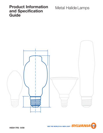
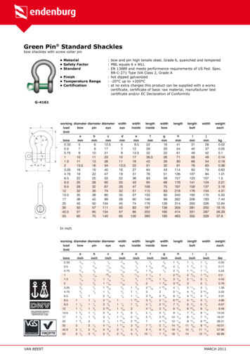
WIRE DIAGRAMS FOR 1-LAMP EMERGENCY OPERATIONEMERGENCY BALLAST AND AC BALLAST MUST BE FED FROM THE SAME BRANCH CIRCUITTYPICAL SCHEMATICS ONLY. MAY BE USED WITH OTHER BALLASTS. CONSULT THE FACTORY FOR OTHER WIRING DIAGRAMS.C. TWO (2) LAMP PREHEAT BALLAST (Lamp 2 operates in emergency mode)2.A) FLEX Conduit Wiring Diagram:1.B) FLEX Conduit Wiring Diagram:WHITECOMMONUNSWITCHED HOTBLACK 120VORORANGE 277V(CAP UNUSED L/BLKACBALLASTWHITEBREDVIOLET ERTERCONNECTORLAMP 1sLAMP 2D. ONE (1) LAMP CHOKE BALLAST2.A) FLEX Conduit Wiring Diagram:1.B) FLEX Conduit Wiring Diagram:WHITECOMMONBLACK 120VORORANGE 277VUNSWITCHED HOT(CAP UNUSED LEAD)WALLSWITCHWHT/BLKBLUEBBCHOKE BALLASTBLU/WHTSVIOLET EDWHITEINVERTERCONNECTORE. ONE (1) LAMP RAPID START BALLAST2.A) FLEX Conduit Wiring Diagram:1.B) FLEX Conduit Wiring Diagram:WHITECOMMONBLACK 120VORORANGE 277VUNSWITCHED HOT(CAP UNUSED ASTVIOLET BROWN-LCTSREDWHITEINVERTERCONNECTORLAMPF. TWO (2) LAMP RAPID START BALLAST (Lamp 2 operates in emergency mode)2.A) FLEX Conduit Wiring Diagram:1.B) FLEX Conduit Wiring Diagram:WHITECOMMONUNSWITCHED HOTBLACK 120VORORANGE 277V(CAP UNUSED ET BAEMERGENCYBALLASTABROWN-REDWHITELAMP 1LAMP 2LCTSINVERTERCONNECTOR
WIRE DIAGRAMS FOR 1-LAMP EMERGENCY OPERATIONEMERGENCY BALLAST AND AC BALLAST MUST BE FED FROM THE SAME BRANCH CIRCUITTYPICAL SCHEMATICS ONLY. MAY BE USED WITH OTHER BALLASTS. CONSULT THE FACTORY FOR OTHER WIRING DIAGRAMS.G. ONE (1) LAMP CIRCLINE RAPID START BALLAST2.A) FLEX Conduit Wiring Diagram:1.B) FLEX Conduit Wiring Diagram:UNSWITCHED HOTBWHITECOMMONBLACK 120VORORANGE 277VWALLSWITCH(CAP UNUSED EDACBALLASTBLACKVIOLET NNECTORLAMPH. TWO (2) LAMP CIRCLINE RAPID START BALLAST (22 watt lamp operates in emergency mode)2.A) FLEX Conduit Wiring Diagram:1.B) FLEX Conduit Wiring Diagram:WHITECOMMONBBLACK 120VORORANGE 277VUNSWITCHED HOT(CAP UNUSED ASTYELL/BLKYELLOW32 WATTLAMPAVIOLET BROWN-LCTSREDWHITEINVERTERCONNECTOR22 WATTLAMPI. ONE (1) FOUR PIN COMPACT LAMP RAPID START BALLAST2.A) FLEX Conduit Wiring Diagram:1.B) FLEX Conduit Wiring Diagram:WHITECOMMONBLACK 120VORORANGE 277VUNSWITCHED HOTWHITEWALLSWITCHBLACK(CAP UNUSED LEAD)WHT/BLKBLUEBLUEBLU/WHTACBALLASTBLUEREDBVIOLET CTSREDWHITEINVERTERCONNECTORJ. TWO (2) LAMP RAPID START BALLAST2.A) FLEX Conduit Wiring Diagram:1.B) FLEX Conduit Wiring Diagram:COMMONUNSWITCHED HOTWHITEBLACK 120VORORANGE 277V(CAP UNUSED TYELLOWLAMP 1LAMP 2BLUEREDREDBLUEBLU/WHTYELL/BLKYELLOWREDVIOLET ECTOR
WIRE DIAGRAMS FOR 1-LAMP EMERGENCY OPERATIONEMERGENCY BALLAST AND AC BALLAST MUST BE FED FROM THE SAME BRANCH CIRCUITTYPICAL SCHEMATICS ONLY. MAY BE USED WITH OTHER BALLASTS. CONSULT THE FACTORY FOR OTHER WIRING DIAGRAMS.K. ONE (1) LAMP WITHOUT AC BALLAST2.A) FLEX Conduit Wiring Diagram:1.B) FLEX Conduit Wiring Diagram:WHITECOMMONUNSWITCHED HOTBLACK 120VORORANGE 277V(CAP UNUSED LEAD)CAPCAPCAPWHT/BLKBBLUEVIOLET CTSREDWHITEINVERTERCONNECTORLAMPL. ONE (1) FOUR PIN COMPACT LAMP WITHOUT AC BALLAST2.A) FLEX Conduit Wiring Diagram:1.B) FLEX Conduit Wiring Diagram:WHITECOMMONUNSWITCHED HOTBLACK 120VORORANGE 277V(CAP UNUSED REDBVIOLET CTOR
When used with ceiling mounted downlight fixtures, the EMERGENCY BALLAST should be mounted on the fixture above the ceiling. The flex conduit marked " A" should be wired into the ballast/lamp compartment or to an electrical junction box on the fixture which allows access to the ballast/lamp