Transcription
E225C – Lecture 16OFDM IntroductionEE225CIntroduction to OFDMlBasic idea» Using a large number of parallel narrow-band subcarriers instead of a single wide-band carrier totransport informationlAdvantages» Very easy and efficient in dealing with multi-path» Robust again narrow-band interferencelDisadvantages» Sensitive to frequency offset and phase noise» Peak-to-average problem reduces the powerefficiency of RF amplifier at the transmitterlAdopted for various standards– DSL, 802.11a, DAB, DVB1
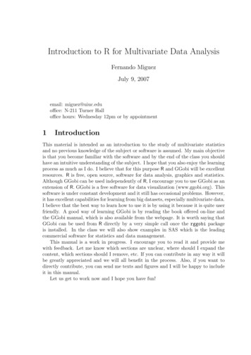
Multipath can be described in two domains:time and frequencyTime domain: Impulse responsetimetimetimeImpulse responseFrequency domain: Frequency responsetimetimetimeSinusoidal signal as inputftimeFrequency responseSinusoidal signal as outputModulation techniques:monocarrier vs. multicarrierChannelN carriersChannelizationSimilar toFDM techniqueGuard bandsBPulse length 1/B– Data are transmited over only one carrierDrawbacksBPulse length N/B– Data are shared among several carriersand simultaneously transmittedAdvantages– Selective FadingFurthermore– Flat Fading per carrier– Very short pulses– N long pulses– ISI is compartively long– ISI is comparatively short– EQs are then very long– N short EQs needed– Poor spectral efficiencybecause of band guards– Poor spectral efficiencybecause of band guards– It is easy to exploitFrequency diversity– It allows to deploy2D coding techniques– Dynamic signallingTo improve the spectral efficiency:Eliminate band guards between carriersTo use orthogonal carriers (allowing overlapping)2
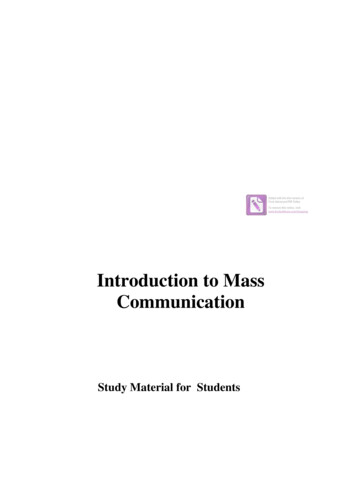
Orthogonal Frequency Division ModulationN carriersSymbol: 2 periods of f0Transmit fSymbol: 4 periods of f0fBSymbol: 8 periods of f0Channel frequencyresponseData coded in frequency domain Transformation to time domain:each frequency is a sine wavein time, all added up.Decode each frequencybin separatelyReceivetimefBTime-domain signalFrequency-domain signalOFDM uses multiple carriersto modulate the dataN carriersFrequencyTime-frequency gridBDataCarrierf0BFeatures– No intercarrier guard bands– Controlled overlapping of bands– Maximum spectral efficiency (Nyquist rate)– Easy implementation using IFFTs– Very sensitive to freq. synchronizationT 1/f0One OFDM symbolTimeIntercarrier Separation 1/(symbol duration)Modulation techniqueA user utilizes all carriers to transmit its data as coded quantity at eachfrequency carrier, which can be quadrature-amplitude modulated (QAM).3
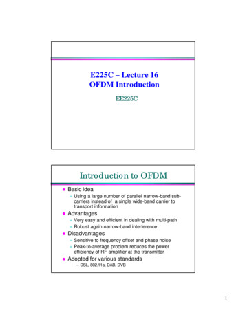
OFDM Modulation and Demodulationusing FFTsd0b0d1P/SIFFTb1d2d0, d1, d2, ., dN-1b2Inverse fastd3Parallelto.Fourier transform.serial converter.Transmit time-domain.f .samples of one symbol.timebN-1dN-1Data coded inData in time domain:frequency domain:one symbol at a timeone symbol at a timed0’d1’d2’.dN-1’S/Pd0’, d1’, ., dN-1’Receive time-domainsamples of one symbolSerial toparallel convertertimeDecode eachb0’frequency binb1’independentlyb2’.f .bN-1’FFTFast FouriertransformLoss of orthogonality (by frequency offset)ψ k (t) exp( jk 2π t / T ) y ψ k m ( t) exp ( j2π (k m )t / T )Transmission pulsesψ k m (t) exp ( j2π (k m δ ) / T ) con δ 1 / 2δReception pulse with offset δInterference betweenchannels k and k mI m (δ) Summing up mπ m δ ImN 12m(δ ) (Tδ)2 m 1123 (Tδ )214m2-10m 1-20m 3m 5m 7-50Asymetric-70-0.4-0.3-0.20-0.10.1Frequency offset: j 2π(m δ )N 1 (N 5Is enough )Total ICI due to loss of orthogonality-40-60forT (1 exp( j2πδ ))-10-15δ 0.05-20-25δ 0.02-30δ 0.01-35δ 0.005-40Practical-45δ 0.002δ assumedr.v.-50δ 0.001Gaussianσ δ-55-60246810121416Carrier position within the band (N 16)ICI in dBInterference: Im(? )/T en dBT0Loss for 8 carriers0-30T sin πδI m (δ ) exp( jk2πt / T ) exp( j(k m δ )2πt / T )dt 0.20.30.4limit4
Loss of orthogonality (time)Let us assumea misadjustment τThenif m k-lXi c 0 T /2 τ T /2ψ k (t )ψ l (t τ )dt c 1 *τ senmπ 2 TT , c c01Xi mπ 0,c0 c1 In average, the interferingpower in any carrier is X 2E i2 TT/ 2independenton mτ 2 , τ T T Per carrierICI 20log22 1 τ 1 τ 4 T 2 0 2 2 T ICI due to loss of orthogonaliy45Doubling N means 3 dB more ICI40m 135ICI in dBInterference en dBτXi 2mπ Tτ 2TTmπOr approximately,when τ TLoss for 16 carriers0-5-10-15-20-25-30-35-40-45-5002 consecutivesymbolsψ k (t )ψ l (t τ )dt* T / 2 τm 5m 10τ assumed an Uniform r.v.3025Max. practical limitN 820150.10.2Zone of interest0.3 0.4 0.5 0.6 0.7Relative misadjustment τ0.80.91100N 640.010.020.030.040.050.060.070.08Typical deviation for the relative misadjustmentIncluding a “cyclic prefix”To combat the time dispersion: including ‘special’ time guards in the symbol transitionsco p yFurthemore it converts Linear conv. Cyclic conv.CPτ(Method: overlap-save)TTcWithout the Cyclic PrefixIncluding the Cyclic PrefixSymbol: 8 periods of fiInitial transientChannel:h(n ) (1 ) – n / nn 0 , ,2 3 Ψ i(t)Loss of orthogonalityDecaying transientSymbol: 8 periods of fiPassing the channel h(n)Passing the channel h(n)CPΨi(t)Ψi(t)Initial transientremains withinthe CPThe inclusion of a CPmaintains the orthogonalityΨj (t)Ψ j(t)Symbol: 4 periods of fiFinal transientremains withinthe CPSymbol: 4 periods of fiCP functions:– It acomodates the decaying transient of the previous symbol– It avoids the initial transient reachs the current symbol5
Cyclic PrefixTgTMulti-path componentsτmaxTxTSampling start802.11a System Specificationt1 t2 t3 t4 t5 t6 t7 t8 t9 t10GI2Short training sequence:AGC and frequency offsetlllllT1T2GIOFDM SymbolGIOFDM SymbolLong training sequence:Channel estimationSampling (chip) rate: 20MHzChip duration: 50nsNumber of FFT points: 64FFT symbol period: 3.2µsCyclic prefix period: 16 chips or 0.8µs» Typical maximum indoor delay spread 400ns» OFDM frame length: 80 chips or 4µs» FFT symbol length / OFDM frame length 4/5lModulation scheme» QPSK: 2bits/sample» 16QAM: 4bits/sample» 64QAM: 6bits/samplelCoding: rate ½ convolutional code with constraint length 76
Frequency diversity using codingRandom errors: primarily introduced by thermal and circuit noise.Channel-selected errors: introduced by magnitude distortion inchannel frequency response.Data bitsFrequencyTime-frequency gridBBad carriersf0fFrequency responseT 1/f0TimeErrors are no longer random. Interleaving is often used to scramblethe data bits so that standard error correcting codes can be applied.Spectrum MaskPower Spectral Density-20 dB-28 dB-40 dB-30-20-11 -9f carrier9 112030Frequency (MHz) Requires extremely linear power amplifier design.7
Adjacent Channel andAlternate Channel RejectionDaterate6 MbpsM inimumSensibility-82 d B mAdjacent ChannelRejection16 dBAlternateChannel rejection32 dB12Mbps-79 d B m13 dB29 dB24Mbps-74 d B m8 dB24 dB36Mbps-70 d B m4 dB20 dB54Mbps-65 d B m0 dB15 dB32 dB blocker16 dB blockerSignalFrequency Requires joint design of the anti-aliasing filter and ADC.OFDM Receiver DesignYun Chiu, Dejan Markovic, Haiyun Tang,Ning ZhangEE225C Final Project Report, 12 December20008
OFDM System Block DiagramSynchronizationlFrame detectionFrame startTgTlFrequency offset compensationlSampling error» Usually less 100ppm and can be ignored– 100ppm off 1% of a sample every 100 samples9
System Pilot StructureIEEE 802.11a OFDM TxerShort Preamble Gen.Long Preamble Gen.OFDM Data Path10 x 0.8 8 uS1 2345 672 x 0.8 2 x 3.2 8 uS89 10GI2T1T2Signal Detection, AGC,Channel & Fine Freq.Diversity SelectionOffset EstimationCoarse Freq. OffsetEst.,Timing Sync.0.8 3.2 8 uS 0.8 3.2 8 uS 0.8 3.2 8 uSGISignalRate, LengthGIDataDataGIDataData10
Short & Long Preambles1 j-24-20-12-16-1-jfShort PreamblePeriod 16 Chips 1-26-24-16-12f-1Long PreamblePeriod 64 ChipsCorrelation of Short PreambleCorrelationFine TimingAutoCorrelationCoarse Timing11
SynchronizationFrom AGC16TdTdTd*TdTd*TdTd. T. **d.ΣMoving AutoCorr. UnitTdFrom AGCTdMoving SPCorr. UnitTd*Td*. T. **dΣ.Short Preamble (LUT)Impairments: Multi-Path ChannelTc002TTT02Tt0TT2T3T4T00TtcCh. 4Tt5TAuto-Correlation w/Multi-Path ChannelResponse.12
Impairments: Frequency Offset00TT2T2T3T3T4T4Tttt0T2T3T4TtFine Frequency Offset Est.AccumulatorComplexMultiplierSync. Signal13
0Coarse-Fine Joint Estimation &Decision Alignment Error Correctionππ3415860πAverage over64 chipsπB AC D π70ππAverage over16 chips200CoarseFineFolding Signalπ0VinFolding ADC 100ppm fc@ 5.8GHz0π0πFrequency Offset CompensationDecisionAlignmentChannelJoint CoarseFine Est.Offset Corr.14
Performance SummaryParametersMetricsNumber of sub-carriers48 data 4 pilotOFDM symbol freq.4 µsModulation SchemeBPSK up to 64-QAMSampling clock freq.20 MHzSync. Frame Start AccuracyFreq. Offset Est. Range 8 chips (CP 16chips) 5π 100ppm @ 5.8 GHzFreq. Offset Est. Accuracy1% (@ 15dB SNR)Critical path delay12.7 nsSilicon area397,080 µm2Total power consumption3.4 mW @ 20 MHz15
6 Cyclic Prefix T g T τ max T x Multi-path components Sampling start T 802.11a System Specification l Sampling (chip) rate: 20MHz l Chip duration: 50ns l Number of FFT points: 64 l FFT symbol period: 3.2µs l Cyclic prefix period: 16 chips or 0.8µs » Typical maximum indoor del