Transcription
Database Schema DesignUsingEntity-Relationship Approach(ER Approach or ER Model)Tok Wang LingNational University of Singapore1
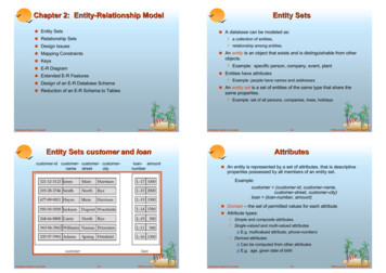
Topics Concepts/Constructs in ER Approach and diagramo Cardinality vs. Participation Constrainto Weak Entity Type, EX/ID Relationship Types, generalizationand specializationo Some extensions: Aggregation, Multiple FDs Representation English Sentence Structure and ER Diagramo self study ER Construct Notation Comparison Database Schema Design using ER Approach Translation of a (Normal Form) ER Diagram to a RDB A Normal Form for ER DiagramER Model2
ER approach was proposed by Prof. Peter Chen in TODS 1, 1976. Main Concepts:- entity (i.e. object)- relationship- nd (role)wife (role)(relationship)Brief ideas:English correspondencenoun entityverb relationshipMarried toRef:ER Model Peter Chen paper TODS 1976Elmasri&Navathe’s bookKorth’s bookHawryzkiewycz’s book3
Entity: An entity is an object which exists in our mindand can be distinctly identified.Q: How to identify entities?E.g. - Ng Hong Kim with NRIC S0578936I- Account# 563978 of DBS Bank- Car with car plate number SBG 3538PEntity type- Entities can be classified into different types.- Each entity type contains a set of entities eachsatisfying a set of predefined common properties.E.g. Employee, Student,Car,House,Bank AccountQ: What are the common properties of each of the above entity types?ER Model4
List of common entity types: People: humans who carry out some functionEmployees, students, customers Places: sites or locationsCities, offices, routes, countries Things: tangible physical objectsEquipments, products, buildings OrganizationsTeams, suppliers, departments Events: things that happen to some other entity at a givendate and time or as steps in an ordered sequence.Employee promotions, project phases, account payments Concepts: intangible ideas used to keep track of business orother activities.Projects, accounts, complaintsER Model5
Relationship. A relationship is an association among severalentities.E.g. A relationship which associates customer Ng Hong Kim identifiedby NRIC S0578936I and DBS bank account 5075610.Relationship type (or Relationship set)Each relationship type contains a set of relationships of the sametype each satisfying a set of predefined common properties.If E1, E2, , En are entity types, then an n-ary relationship typeR is a subset of the Cartesian Product E1 E2 En,i.e.R E1 E2 Enor R {(e1, e2, , en) ei Ei, i 1,2, ,n}where (e1, e2, , en) is a relationship.When n 2 (or 3), we call R a binary (or ternary) relationship type.E.g. We define a binary relationship type Work to denote the associationbetween two entity types Department and the EmployeeWork Department Employee6
Attribute An entity type E (or a relationship type R) has attributesrepresenting the structural (static) properties of E (or R resp.). An attribute A is a mapping from E (or R ) into a CartesianProduct of n values sets, V1 V2 Vn. If n 2 , then we call attribute A a composite attribute,otherwise (i.e. when n 1) call it a simple attribute.E.g. DATE is a composite attribute with values setsDAY, MONTH, YEAR The mapping can be one-to-one (1:1), many-to-one (m:1),one-to-many (1:m), many-to-many (m:m). If an attribute A is a 1:1 or m:1 mapping from E (or R)into the associated value sets, then A is called a single valuedattribute, otherwise it is called a multivalued attribute.ER Model7
Note the difference between type and instance. We useo entity type vs. entityo relationship type vs. relationshipo attribute vs. attribute valueSome books and papers use slightly different terms:o entity and entity instanceo relationship and relationship instanceo attribute and attribute valueSome books and papers just don’t differentiate them,simply use entity and relationship for both type andinstance, may have interpretation problem.ER Model8
Entity-Relationship Diagram (ER Diagram or ERD) The structure (i.e. schema) of a database organizedaccording to the ER approach can be represented by adiagrammatic technique called an Entity-Relationshipdiagram.- entity type rectangle- relationship type diamond- attribute ellipseNotation:CardinalitymEMPEmp# udgetm:1m:m1:11:m(single valued attribute)(multi-valued attribute)(one to one attribute)(one to many attribute)Note: There are some other different representations (notations). Many booksdon’t use arrows and have problem to interpret ER diagrams precisely.9
Different cardinalities of binary relationship typesEmpn1workDeptFD: Emp Deptwork is a many to one relationship typeMgr1manage1DeptFDs: Mgr DeptDept Mgrmanage is a one to one relationship typeEmpnworknProjectNo FD between Emp and Project,work is a many to many relationship type.Q: What are the intuitive meanings of the above relationship types?ER Model10
Composite AttributeE1E2E3MonthDayE123YearE.g.Name, Date, and E123 arecomposite rnameNote:A line joining the two attributes’arrows indicates the two attributesform a key of the entity type Patient.Given nameE.g. P1 and P2 form a key of Patient.Identifier of entity type- A minimal set of attributes K of an entity type E which definesa one-to-one mapping from E into the Cartesian Product of theassociated value sets of K is called a key of E.- One of the keys of an entity type is designed as the identifier. Q: How to choose the identifier of an entity type?E.g. Registration#, NRIC#, and {P1, P2} are 3 keys of PATIENT entity type, wechoose Registration# as the identifier. Why? Q: Are the concepts of identifier of entity type and primary key of relation ofrelational model the same? If not, what are the main differences between them?11
Identifier of relationship type Let K be a set of identifiers of some entity types participatingin a relationship type R. K is called a key of the relationshiptype R if there is an 1:1mapping from R into the CartesianProduct of the associated value sets of K and no proper subsetof K has such property. One of the keys of R is designated as the identifier of R. Q: Why do we need to define identifiers for relationship types? How?E.g. {Emp#, Proj#} is the only key of the relationship type“ work” in the previous EMP-PROJ ER # is the identifier of the binary relationship type Belong.12
Recursive relationship typerole name1SuperiorSTAFFManagesm alrole name Q: How to represent recursive relationship type and in arelational database?Two relationship types between the same set of entity typesmlive-inPersonm1Houseownm Q: How to represent these 2 relationship types in a relational database?13
Participation Constraint - another way to specify constraints:E.g. Students take coursesStudent2:8Takes4:mCourseHere 2:8 means each student must take at least (minimum) 2courses and at most (maximum) 8 courses.4:m means each course must have minimum 4 students and nomaximum limit. (m means many, no limit).If every entity of an entity type must participate in some relationship(s) ofthe relationship type then that entity type has total (or mandatory)participation in the relationship type.If some entities of an entity type need not participate in any relationship ofthe relationship type then the participation of that entity type in therelationship type is partial (or optional). Q: What are the differences between cardinality and participationconstraint? Which one is better (i.e. more powerful)?14
Ternary relationship typeSuppliermPartmmSPJNo FDs among Part, Supplier, and Project.It is a m:m:m ternary relationship type.ProjectProvider1Owner1nSPJPhoneFD: Phone Owner, ProviderSupplier1PartmSPJmFD: Part, Project SupplierProjectA1B1R1FDs: A B CB ACC ABCER Model15
Subtype relationship (IS-A hierarchy)LivingCreatureIS-A relationship is the same asthe sub-class relationship in lePersonFemalePersonAnother notationSet-operation relationshipsJoint Appointment(E&B) FacultyPersonUnionFemalePersonNote the directionsof the ulty16
Decomposition relationship typeProfessorNote the directionsof the arrows.By RankFull ProfessorsAssociate ProfessorsAssistant ProfessorsER Model17
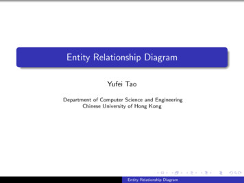
Existence-dependency (EX) relationship type and weak entity typeE.g.Note thedirections ofthe arrows.EmployeeFD: NRICName, DOB, SexEXHas ChildNRICChildNote: NRIC is the identifier of the entity type Child.NameDOBSexThe existence of a Child entity depends on the existence of an associatedEMPLOYEE entity. Thus, if an Employee entity is deleted, its associatedChild entities are also deleted.The dependent entity type Child is a weak entity type (represented by a doublerectangle), and Employee is a regular entity type.Relationship type which involves a weak entity type is called existencedependency relationship type (denoted with “EX” together with a relationship type name).Note: An EX relationship type is a 1:m (one to many) relationship type.18
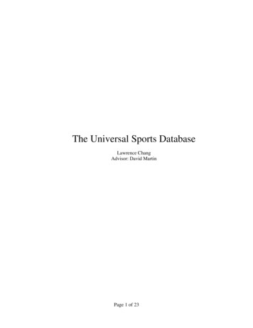
Identifier-dependency (ID) relationship type An entity cannot be identified by the value of its ownattributes, but has to be identified by its relationship withother entity. Such a relationship is called identifierdependency relationship.E.g.Note: The line on the arrow to the attributeGiven name indicates this attribute together with theidentifier of Employee (i.e. E#) form the identifier ofthe weak entity type Child. So, we have:EmployeeE#IDHas ChildNote thedirections ofthe arrows.Given nameDOBChildFD:E#, Given nameDOB, SexNote: The Child has no NRIC attribute.SexNote: By the original definitions, an identifier-dependency relationshiptype (denoted by ID) is also an existence-dependency relationshiptype. However, we should not just indicate an ID as EX.Q: What are the differences between this ER diagram and the previous page’s ER diagram. Note: ID dependency relationships occur in XML data quite often.19
Another example of Identifier-dependency relationship typecountryIDprovinceIDNote: Different provinces of a countrymay have cities with the same name. So,city name cannot be used to identify acity.E.g. City Waterloo, Ontario, CanadaCity Waterloo, Iowa, USCity Waterloo, Illinois, UScityQ: What are the identifiers of the entity types province and city?ER Model20
Generalization and Specialization Generalization is the result of taking the union of two or more(lower level) entity types to produce a higher level entity type. Specialization is the result of taking a subset of a higher-levelentity type to form a lower-level entity type. Generalization is the same as UNION.Specialization is the same as ISA. In generalization, every higher-level entity must also be a lowerlevel entity.Specialization does not have this y-dateFixed-depositChecking-AccountNote: There are other types of accounts, e.g., AUTOSAVE account and Fixed Deposit account.21
aff Generalization is used to emphasize the similarity amonglower-level entity types and to hide their difference.Specialization is the inverse, i.e. to highlight the specialproperties of the lower level entity types. The attributes of the higher-level entity types are to beinherited by lower-level entity types.Another notation (Bad! fNonacad-Staff(Generalization)(Specialization)(use thick lines)ER Model22
Some extensions to the ER approach(1) The ER approach does not allow relationships among relationships.E.g. In an EMPLOYEE database, we want to describe informationabout employee who work on a particular project and use anumber of different machines doing that work.Using the basic ER approach, we may have the ER diagram.EmployeeWorkProjectUsesMachineryNote: The constraint between the two relationship types Work and Usesis not captured explicitly in the above ER diagram.Q: How do we capture this constraint in an ER diagram?Q: Can we combine the 2 relationship types into one?23
One solution is use aggregation.Aggregation is an abstraction through which relationshipsare treated as higher-level entities.EmployeeWorkProject(not a good notation)UsesMachineryIn the ER diagram, we treat the relationship type Work and theentity types Employee and Project as a higher-level entitytype called Work. My better notation:EmployeeWorkProjectUses MachineryNote: The line joining the diamond ofthe “Uses” relationship type and theaggregation does not touch the diamondof the “Work” relationship type.Note: The constraint is explicitlycaptured by the 2 ER diagrams, i.e.Uses [Employee, Project] Work24
(2) We introduce a new construct called composite forconstructing complex objects (complex entities) from someother simple and/or complex objects.The complex object and its component objects are notnecessarily type (or object) iving-RoomBed-RoomNote: COMPOSITE is similar to IS-PART-OF relationship but not exactly the same.E.g.ApartmentIS-PART-OFIS-PART-OFNote: An apartment may haveother components, e.g. kitchen.Bath-RoomBed-Room25
(3) Represent more than one FD in a relationship type(using more than one set of erThere are 2 FDs in the relationship type Take:Student, Subject TeacherTeacher Subject Note: “-” means the entity type is not involved the respective set of cardinalities.ER Model26
1mHospitalQ: Why ientTestmDiagnosisFigure: Entity-relationship diagram for medical database.(from Tsichritzis’s book)27
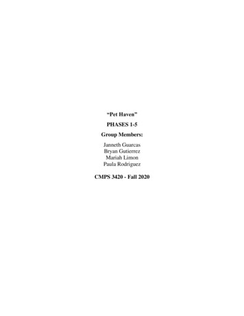
DEPARTMENT1DEPT EMPmEMPLOYEE1mmPROJECT1EXor IDSUPPLIERPROJ WORKPROJMANAGERmmmSUPPPART PROJmmSUPP PARTmPARTEMP DEPmmmDEPENDENTPARTSTRUCTUREFigure: An Entity-relationship diagram.Note: The relationship type EMP DEP can be EX or ID depending on whetherDEPENDEMT has identifier or not.Q: Is there any constraint between SUPP-PART and SUPP PART PROJ ?Ans: Yes.28Q: What is the constraint?
(A better solution)DEPARTMENT1SUPPLIERPROJ WORKDEPT EMPmmmmPROJECTEMPLOYEEm11EXor IDEMP DEPPROJMANAGERSUPPPART PROJSUPP PARTmmmPARTmmmPARTSTRUCTUREDEPENDENTConstraint shown by the aggregation is:SUPP PART PROJ [SUPPLIER, PART] SUPP PART [SUPPLIER, PART]ER Model29
English Sentence Structure and ER Diagram(self study)Ref: Peter P Chen. English Sentence Structure and Entity-Relationship Diagrams.1983 Inf Sci 29(2-3) :127-149.In order to construct a database using an ER diagram, the databasedesigner not only has to interview users but also must study the systemspecification documents which are written in some natural language,such as English.Some guidelines/rules for translating English sentences into ERdiagrams are presented below:Guideline 1: A common noun (such as student and employee)in English corresponds to an entity type in an ER diagram:common nounentity typeNote: Proper nouns are entities not entity types, e.g. John, Singapore, New York City.ER Model30
Guideline 2: A transitive verb in English corresponds to arelationship type in an ER diagram:transitive verbrelationship typeNote: A transitive verb must have an object.E.g. A person may own one or more cars and a car is ownedby only one person.personO1ownsmcarNote: The cardinalities of person and car in the owns relationship type are 1 and m respectively, and theparticipation of person in the owns relationship type is optional (or partial) participation as some peoplemay not own any car. Alternatively, we can have the participation constraints of person and car as 0:m and1:1 respectively. Since a car must have an owner, the participation of car in the owns relationship type ismandatory (or total) participation.Guideline 3: An adjective in English corresponds to an attributeof an entity type in an ER diagram:adjectiveattribute of entity typeE.g. A London supplier, a red part, a male person.31
Guideline 4: An adverb in English corresponds to an attributeof a relationship type in an ER diagram:adverbattribute of relationship typeE.g. A London supplier sells a part with part name lampfor 50.suppliersellslocationprice“London”“ 50”partpname“lamp”London and Lamp are adjectives (and attribute values) of supplier and part resp, and 50 is an adverb which is an attribute of the relationship type sells.ER Model32
Guideline 5: A gerund in English corresponds to a high levelentity type (or aggregation) converted from a relationshiptype in an ER diagram:gerundaggregation(or high level entity type)Note: A gerund is a noun in the form of the present participle of a verb.For example 'shopping' in the sentence 'I like shopping‘.E.g. Products are shipped to customers, and the shipping isperformed by delivery men.productShip tocustomerPerformedbyDelivery manER Model33
Guideline 6: A clause in English is a high level entity typeabstracted from a group of interconnected low level entityand/or relationship types in an ER diagram:clauseaggregation (or high level entity type)Note: A clause is a group of words that contains a subject and a verb, but it is usuallyonly part of a sentence.E.g. Managers decide which machine is assigned towhich mployee(One representation,not so good)machineAssignedtoemployeedecidemanagerQ: Which representation is better?ER Model(Another representation,better one)34
ER Construct notation Comparisonused in Teorey's bookfor cardinalityER Model construct using the"crow's foot"- notationfor participation constraint[Ever85, Knowledgeware]ER Model Construct usingER Model Construct[Rein85]the Chen approachfor cardinalityMin 0Max 1Min ference1PaperPaperpublishNpublishconferenceMax 1PaperEditorPaperMax lishersupplierJournalsupplypartNotation: O means optional participation.ER Model35
ER Construct Notation Comparison (cont.)used in Teorey's bookfor cardinalityER Model construct using the"crow's foot"- notationfor participation constraint[Ever85, Knowledgeware]ER Model Construct usingER Model Construct[Rein85]the Chen approachfor cardinalityPrev-NamePrev-NamePrev-NameWeak EntityorIntersection EnityWeak EntityIntersection orRecursive entityRecursive werIs-group-leader-ofIs-group-leader-ofRecursive relationshipmmWritten-at?Can't represntn-ary relationships1InstitutionN-ary relationshipER Model36
ER Construct Notation Comparison (cont.)ER Model Construct usingER Model Constructused in Teorey's bookfor cardinalityidentifier (key)[Rein85]editor-idthe Chen approachfor cardinalityER Model construct using the"crow's foot"- notationfor participation constraint[Ever85, Knowledgeware]No attributes areNameallowed forrelationshipsdescriptor ecialty-areasm:1AttributeNameNo attributes for relationshipsQ: What are the strong and weak points of each notation?ER Model37
Some other ERD notationsMultivalued attributeID dependency relationshipTotal participation, i.e. min occur is 1XRcircleareaYDotted oval and lineindicate derived attribute 38
AnimaldLionHorseDogBookUTextNovelPoetryDisjoint – every member of thesuper-class can belong to at mostone of the subclasses. Forexample, an Animal cannot be a lionand a horse, it must be either a lion,a horse, or a dog.Union – every member of thesuper-class can belong tomore than one of thesubclasses. For example, abook can be a text book, butalso a poetry book at thesame time.ER Model39
Example ERD notation.Underlined attributes are identifiers (key attributes) of entity types.ER Model40
Example ERD notation.Notations for disjoint and overlap subclasses.41
Another ERD notation.Arrow of a relationship type show the functional dependency.E.g. Course GradEmail Studentin TA relationship type;in Of relationship type.ER Model42
Steps of database design using ER ApproachStep 1. Understand the problem domain. Analyzedatabase requirements.– Write a summary specification if not created yet.– What do we need to store into the database?– What queries and reports do we need to generate?– What are important people, places, physical things,organizations, events and abstract concepts in theorganization?Step 2. Design a conceptual database schema by creatingan ER diagram. Detail will be discussed.ER Model43
Step 3. Design a logical database schema.- Convert the ERD to a normal form ERD.- Translate the ERD into a relational schema.Note: Another approach. First translate the ERD to a relational database schema,then normalize the relations in the schema to at least 3NF.Step 4. Design a Physical database schema.- Denormalization. May need to de-normalize some normal formrelations for better performance.* adding redundant attributes in some relations* adding derived attributes in some relations* merging/splitting relations.-choosing primary keys and foreign keysdefining indexesDo database prototyping & modify the design if necessary.Summarize the design assertion (integrity, security).Detail will be discussed in the Physical Database Design chapter.Step 5. Verify the design with users. Iterate the steps if necessary.ER Model44
Design a conceptual schema by creating an ER diagramStep 1.Step 2.Step 3.Step 4.Step 5.Identify the entity types.Identify the relationship types and their participating entitytypes.Identify the attributes, keys, and identifier of each entitytype and relationship type and obtain an ER diagramConvert the ER diagram to a normal form ER diagram.Translate the NF-ER diagram to a relational databaseschema (or other data models)Question: Is the resulting relational schema in normal form?Advantages: DBMS independent Concentrate on “information requirements” not on“storage or access efficiency”, i.e. conceptual design. Easy to understand by users and database designersER Model45
Some decision rules/guidelinesRule 1:Every entity type should be important in its own rightwithin the problem domain.Rule 2:IF an entity type (noun) has only one property to store andrelates to only one other entity typeTHEN it is an attribute of another entity typeELSE it is an entity type.Rule 3:IF an entity type has only one data instanceTHEN do not model as an entity type.Rule 4:IF a relationship type needs to have a unique identifierTHEN model it as an entity type.The first three rules are used to evaluate entity/object types or nouns, andthe fourth rule is used to evaluate relationship types or verbs.ER Model46
Example 1.(from C J Date’s book Question 14.2)A database used in an order-entry system is to contain information about customers,items, and orders. The following information is to be included.- For each customer:Customer number (unique)Valid “ship to” addresses (several per customer)BalanceCredit limitDiscount- For each order:Heading information: customer number, “ship-to” address, date of order.Detail lines (several per order), each giving item number, quantity ordered- For each item:Item number (unique)WarehousesQuantity on hand at each warehouseItem descriptionFor internal processing reasons, a “quantity outstanding” value is associated with each detailline of each order. [This value is initially set equal to the quantity of the item ordered and isprogressively reduced to zero as partial shipments are made.]Design a database for this data. As in the previous question, make any semantic assumptionsthat seem necessary.ER Model47
Example 1. (cont.) An Order-Entry System(Question 14.2 in CJ. Date’s book)-First, only decide entity types and relationship types.Customer1EXmOrdermmItemmmWarehouseER Model48
Example 1. (cont.) An Order-Entry System- thenadd attributes of entity types and relationship types.C#AddressBalanceCredit LSDL – Stock Dangerous LevelWarehouseAddressP#Constraints:Between Address & Ship-to-AddressER Model49
Example 2.Recall the supplier-part-project database - ightP#PnameJ#ColorER ModelJname50
Example 3.(From C J. Date’s book Question 14.1)For each department the database contains a department number (unique), a budget value, andthe department manager’s employee number (unique). For each department the database alsocontains information about all employees working in the department, all projects assigned to thedepartment, and all offices occupied by the department. The employee information consists ofemployee number (unique), the number of the project on which he or she is working, and his orher office number and phone number; the project information consists of project number (unique)and a budget value; and the office information consists of an office number (unique) and the areaof the office in square feet. Also, for each employee the database contains the title of each job theemployee has held, together with date and salary for distinct salary received in that job; and fore a c h o f f i c e i t c o n t a i n s t h e n u m b e r s ( u n i q u e ) o f a l l p h on e s i n t h a t o f f i c e .Convert this hierarchical structure to an appropriate collection of normalized relations. Makeany assumptions you deem reasonable about the dependencies involved.DepartmentEmployeeJobSalary historyProjectOfficePhoneER Model51
Example 3. (cont.) (Question 14.1)Department1R4R5mmR6mmR7 1Employee temmR3JobTitle1PhoneDescThere are cycles in the ERD, each cycle may represent a constraint.R3 R1 * R2 [Employee, Phone]R1 R3 * R2 [Employee, Office]R4 R7 * R5 [Employee, Department]R4 R1 * R6 [Employee, Department]Q: What are the meanings of the above constraints?Q: How to know whether these are really constraints or not?Automatically or manually?E.g.52
Example 4. Recall the relation CTX (Course, Teacher, Text)which has a Multivalued dependency (MVD):CourseTeacher TextCoursemNote: CTX has a MVDCTXmmTeacherTextShould be:CoursemNote: CTX can be derived:mmCTCXCTXmTeachermCTX CTmmCXTextER Model53
Example 5. Library Information System.Draw a normal form ER diagram for a university libraryinformation system which stores information about books,journals, publishers, students, staff, borrowing of books,and reservation of books. Note that the library may havemore than one copy for some of the books.54
Example 5. (solution)55
Example 6. Online AuctionConsider an ONLINE AUCTION database system in which members(buyers and sellers) participate in the sale of items. The datarequirements for this system are summarized as follows: The online site has members, each of whom is identified by aunique member number and is described by an e-mail address,name, password, home address, and phone number. A member may be a buyer or a seller. A buyer has a shippingaddress recorded in the database. A seller has a bank accountnumber and routing number recorded in the database. Items are placed by a seller for sale and are identified by aunique item number assigned by the system. Items are alsodescribed by an item title, a description, starting bid price, biddingincrement, the start date of the auction, and the end date of theauction. Items are also categorized based on a fixed classificationhierarchy.ER Model56
Example 6. Online Auction (cont.) Buyers make bids for items they are interested in. Bid price andtime of bid is recorded. The bidder at the end of the auction withthe highest bid price is declared the winner and a transactionbetween buyer and seller may then proceed. The buyer and seller may record feedback regarding theircompleted transactions. Feedback contains a rating of the otherparty participating in the transaction (1-10) and a comment.Design an Entity-Relationship diagram for the ONLINE AUCTIONdatabase. (Do it yourself).ER Model57
Translation of a (normal form) ER diagram toa relational databaseStep 1. Assign role names to certain arcs in a cycle in the ERdiagram (in order to conform to the universal relationassumption).Note. Here, a cycle in an ER diagram is defined as a cycle in thecorresponding graph of the ER diagram in which all entitytypes and relationship types are nodes in the graph andarcs which connect entity types and relationship types areedges in the graph, except for cycles formed only by ISA,UNION, INTERSECT, and DECOMPOSE specialrelationships. Note: We can instead use the relaxed universal relation assumptionwhich only requires the identifiers of entity types be unique.ER Model58
Step 2. Assign identifiers for entity types involved in specialrelationships such as: ISA, UNION, INTERSECT,DECOMPOSE, and so far with no identifiers yet.Step 3. Generate relations for each entity type. (1) All the m:1 and 1:1 attributes of an entity type E form arelation. The keys and identifier of E are the keys andprimary key of the generated relation.(2) Each m:m attribute and the identifier of E form an all keyrelation.(3) Each 1:m attribute and the identifier of E form a relationwith the 1:m attribute as its key.Note. All composite attributes are replaced by their componentsin the generated relations.Q: How about weak entity type?ER Model59
Step 4. Generate relations for each regular relationship type R.(1) All the identifiers (or role names) of the entity types participatingin R a
An entity cannot be identified by the value of its own attributes, but has to be identified by its relationship with other entity. Such a relationship is called . identifier- dependency relationship. E.g. Note: By the original definitions, an identifier-dependency relationship t