Transcription
Chapter 3RADIATION DOSIMETERSJ. IZEWSKADivision of Human Health,International Atomic Energy Agency,ViennaG. RAJANMedical Physics and Safety Section,Bhabha Atomic Research Centre,Mumbai, Maharashtra, India3.1. INTRODUCTIONA radiation dosimeter is a device, instrument or system that measures orevaluates, either directly or indirectly, the quantities exposure, kerma,absorbed dose or equivalent dose, or their time derivatives (rates), or relatedquantities of ionizing radiation. A dosimeter along with its reader is referred toas a dosimetry system.Measurement of a dosimetric quantity is the process of finding the valueof the quantity experimentally using dosimetry systems. The result of ameasurement is the value of a dosimetric quantity expressed as the product ofa numerical value and an appropriate unit.To function as a radiation dosimeter, the dosimeter must possess at leastone physical property that is a function of the measured dosimetric quantityand that can be used for radiation dosimetry with proper calibration. In orderto be useful, radiation dosimeters must exhibit several desirable characteristics.For example, in radiotherapy exact knowledge of both the absorbed dose towater at a specified point and its spatial distribution are of importance, as wellas the possibility of deriving the dose to an organ of interest in the patient. Inthis context, the desirable dosimeter properties will be characterized byaccuracy and precision, linearity, dose or dose rate dependence, energyresponse, directional dependence and spatial resolution.Obviously, not all dosimeters can satisfy all characteristics. The choice ofa radiation dosimeter and its reader must therefore be made judiciously, takinginto account the requirements of the measurement situation; for example, inradiotherapy ionization chambers are recommended for beam calibrations71
CHAPTER 3(reference dosimetry: see Chapter 9) and other dosimeters, such as thosediscussed below, are suitable for the evaluation of the dose distribution(relative dosimetry) or dose verification.3.2. PROPERTIES OF DOSIMETERS3.2.1.Accuracy and precisionIn radiotherapy dosimetry the uncertainty associated with themeasurement is often expressed in terms of accuracy and precision. Theprecision of dosimetry measurements specifies the reproducibility of themeasurements under similar conditions and can be estimated from the dataobtained in repeated measurements. High precision is associated with a smallstandard deviation of the distribution of the measurement results. The accuracyof dosimetry measurements is the proximity of their expectation value to the‘true value’ of the measured quantity. Results of measurements cannot beabsolutely accurate and the inaccuracy of a measurement result is characterized as ‘uncertainty’.The uncertainty is a parameter that describes the dispersion of themeasured values of a quantity; it is evaluated by statistical methods (type A) orby other methods (type B), has no known sign and is usually assumed to besymmetrical.The error of measurement is the difference between the measured valueof a quantity and the true value of that quantity.An error has both a numerical value and a sign.Typically, the measurement errors are not known exactly, but they areestimated in the best possible way, and, where possible, compensatingcorrections are introduced. After application of all known corrections, the expectation value forerrors should be zero and the only quantities of concern are the uncertainties. 3.2.1.1. Type A standard uncertaintiesIf a measurement of a dosimetric quantity x is repeated N times, then thebest estimate for x is x, the arithmetic mean value of all measurements xi:72
RADIATION DOSIMETERSx 1NNÂx(3.1)ii 1The standard deviation sx characterizes the average uncertainty for anindividual result xi and is given by:Nsx Â1(x - x) 2N - 1 i 1 i(3.2)The standard deviation of the mean value is given by:sx 1Nsx 1N ( N - 1)NÂ (xi- x)2(3.3)i 1The standard uncertainty of type A, denoted uA, is defined as thestandard deviation of the mean value, uA s x . The standard uncertainty of type A is obtained by a statistical analysis ofrepeated measurements and, in principle, can be reduced by increasingthe number of measurements. 3.2.1.2. Type B standard uncertaintiesType B standard uncertainties uB cannot be estimated by repeatedmeasurements; rather, they are intelligent guesses or scientific judgements ofnon-statistical uncertainties associated with the measurement. They includeinfluences on the measuring process, application of correction factors orphysical data taken from the literature.It is often assumed that type B standard uncertainties have a probabilitydistribution, such as a normal (Gaussian) or a rectangular distribution (equalprobability anywhere within the given limits). Type B standard uncertaintiescan be derived by estimating the limit beyond which the value of the factor isnot going to lie, and a fraction of this limit is taken as uB. The fraction is chosenaccording to the distribution assumed.3.2.1.3. Combined and expanded uncertaintiesThe equation that determines a dosimetric quantity Q at a point P is ofthe type:73
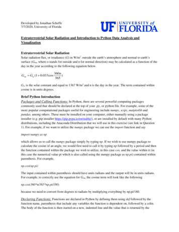
CHAPTER 3NQ P M P Fi(3.4)i 1where M is the reading provided by the dosimetry system and Fi is thecorrection or conversion coefficient. The combined standard uncertainty uC associated with the quantity Q is aquadratic summation of type A (uA) and type B (uB) uncertainties:2uC u A u B2(3.5)The combined uncertainty is assumed to exhibit a normal distribution andis multiplied by a coverage factor, denoted by k, to obtain the expandeduncertainty U kuC. The result of the measurement of the quantity Q isthen expressed by QP U. The expanded uncertainty U with the coverage factor k 2, corresponding to the 95% confidence level, is often used to represent theoverall uncertainty, which relates to the accuracy of the measurement ofthe quantity Q. 3.2.2.LinearityIdeally, the dosimeter reading M should be linearly proportional to thedosimetric quantity Q. However, beyond a certain dose range a non-linearitysets in. The linearity range and the non-linearity behaviour depend on the typeof dosimeter and its physical characteristics.Two typical examples of response characteristics of dosimetry systems areshown in Fig. 3.1. Curve A first exhibits linearity with dose, then a supralinearbehaviour, and finally saturation. Curve B first exhibits linearity and thensaturation at high doses.In general, a non-linear behaviour should be corrected for. A dosimeterand its reader may both exhibit non-linear characteristics, but their combinedeffect could produce linearity over a wider range.3.2.3.Dose rate dependenceIntegrating systems measure the integrated response of a dosimetrysystem. For such systems the measured dosimetric quantity should beindependent of the rate of that quantity.74
RADIATION DOSIMETERSDosimeter readingABDoseFIG. 3.1. Response characteristics of two dosimetry systems. Curve A first exhibitslinearity with dose, then supralinear behaviour and finally saturation. Curve B firstexhibits linearity and then saturation at high doses.Ideally, the response of a dosimetry system M/Q at two different doserates ((dQ/dt)1 and (dQ/dt)2) should remain constant. In reality, the dose ratemay influence the dosimeter readings and appropriate corrections arenecessary, for example recombination corrections for ionization chambers inpulsed beams.3.2.4.Energy dependenceThe response of a dosimetry system M/Q is generally a function ofradiation beam quality (energy). Since the dosimetry systems are calibrated ata specified radiation beam quality (or qualities) and used over a much widerenergy range, the variation of the response of a dosimetry system withradiation quality (called energy dependence) requires correction.Ideally, the energy response should be flat (i.e. the system calibrationshould be independent of energy over a certain range of radiation qualities). Inreality, the energy correction has to be included in the determination of thequantity Q for most measurement situations. Ιn radiotherapy, the quantity ofinterest is the dose to water (or to tissue). As no dosimeter is water or tissueequivalent for all radiation beam qualities, the energy dependence is animportant characteristic of a dosimetry system.75
CHAPTER 33.2.5.Directional dependenceThe variation in response of a dosimeter with the angle of incidence ofradiation is known as the directional, or angular, dependence of the dosimeter.Dosimeters usually exhibit directional dependence, due to their constructionaldetails, physical size and the energy of the incident radiation. Directionaldependence is important in certain applications, for example in in vivodosimetry while using semiconductor dosimeters. Therapy dosimeters aregenerally used in the same geometry as that in which they are calibrated.3.2.6.Spatial resolution and physical sizeSince the dose is a point quantity, the dosimeter should allow the determination of the dose from a very small volume (i.e. one needs a ‘point dosimeter’to characterize the dose at a point). Τhe position of the point where the dose isdetermined (i.e. its spatial location) should be well defined in a referencecoordinate system.Thermoluminescent dosimeters (TLDs) come in very small dimensionsand their use, to a great extent, approximates a point measurement. Filmdosimeters have excellent 2-D and gels 3-D resolution, where the pointmeasurement is limited only by the resolution of the evaluation system.Ionization chamber type dosimeters, however, are of finite size to give therequired sensitivity, although the new type of pinpoint microchambers partiallyovercomes the problem.3.2.7.Readout convenienceDirect reading dosimeters (e.g. ionization chambers) are generally moreconvenient than passive dosimeters (i.e. those that are read after dueprocessing following the exposure, for example TLDs and films). While somedosimeters are inherently of the integrating type (e.g. TLDs and gels), otherscan measure in both integral and differential modes (ionization chambers).3.2.8.Convenience of useIonization chambers are reusable, with no or little change in sensitivitywithin their lifespan. Semiconductor dosimeters are reusable, but with agradual loss of sensitivity within their lifespan; however, some dosimeters arenot reusable (e.g. films, gels and alanine). Some dosimeters measure dosedistribution in a single exposure (e.g. films and gels) and some dosimeters are76
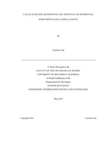
RADIATION DOSIMETERSquite rugged (i.e. handling will not influence sensitivity, for example ionizationchambers), while others are sensitive to handling (e.g. TLDs).3.3. IONIZATION CHAMBER DOSIMETRY SYSTEMS3.3.1.Chambers and electrometersIonization chambers are used in radiotherapy and in diagnostic radiologyfor the determination of radiation dose. The dose determination in referenceirradiation conditions is also called beam calibration (see Chapter 9 fordetails). Ionization chambers come in various shapes and sizes, depending uponthe specific requirements, but generally they all have the following properties:An ionization chamber is basically a gas filled cavity surrounded by aconductive outer wall and having a central collecting electrode (seeFig. 3.2). The wall and the collecting electrode are separated with a highquality insulator to reduce the leakage current when a polarizing voltageis applied to the chamber. A guard electrode is usually provided in the chamber to further reducechamber leakage. The guard electrode intercepts the leakage current andallows it to flow to ground, bypassing the collecting electrode. It alsoensures improved field uniformity in the active or sensitive volume of thechamber, with resulting advantages in charge collection. Measurements with open air ionization chambers require temperatureand pressure correction to account for the change in the mass of air in thechamber volume, which changes with the ambient temperature andpressure. GraphitePTCFEInsulatorCentral electrodeOuter electrodeAluminiumDuralFIG. 3.2. Basic design of a cylindrical Farmer type ionization chamber.77
CHAPTER 3Electrometers are devices for measuring small currents, of the order of 10–9 Aor less. An electrometer used in conjunction with an ionization chamber is ahigh gain, negative feedback, operational amplifier with a standard resistor or astandard capacitor in the feedback path to measure the chamber current orcharge collected over a fixed time interval, as shown schematically in Fig. 3.3.3.3.2.Cylindrical (thimble type) ionization chambersThe most popular cylindrical ionization chamber is the 0.6 cm3 chamberdesigned by Farmer and originally manufactured by Baldwin, but now availablefrom several vendors, for beam calibration in radiotherapy dosimetry. Itschamber sensitive volume resembles a thimble, and hence the Farmer typechamber is also known as a thimble chamber. A schematic diagram of a Farmertype thimble ionization chamber is shown in Fig. 3.2; ionization chamber baseddosimetry systems are discussed in Section 9.2.Cylindrical chambers are produced by various manufacturers, with activevolumes between 0.1 and 1 cm3. They typically have an internal length nogreater than 25 mm and an internal diameter no greater than 7 mm. The wallmaterial is of low atomic number Z (i.e. tissue or air equivalent), with thethickness less than 0.1 g/cm2. A chamber is equipped with a buildup cap with athickness of about 0.5 g/cm2 for calibration free in air using 60Co radiation.The chamber construction should be as homogeneous as possible,although an aluminium central electrode of about 1 mm in diameter is typicallyCfRf-IRf feedback resistor(variable to vary sensitivity) V II Rf (rate mode)V (II t)/Cf(integrated mode)Cf feedback capacitor(variable to vary sensitivity)FIG. 3.3. Electrometer in feedback mode of operation.78
RADIATION DOSIMETERSused to ensure flat energy dependence. Construction details of variouscommercially available cylindrical chambers are given in the IAEA TechnicalReports Series (TRS) 277 and TRS 398 codes of practice. The use of thecylindrical chamber in electron and photon beam dosimetry is discussed inChapter 9.3.3.3.Parallel-plate (plane-parallel) ionization chambersA parallel-plate ionization chamber consists of two plane walls, oneserving as an entry window and polarizing electrode and the other as the backwall and collecting electrode, as well as a guard ring system. The back wall isusually a block of conducting plastic or a non-conducting material (usuallyPerspex or polystyrene) with a thin conducting layer of graphite forming thecollecting electrode and the guard ring system on top. A schematic diagram ofa parallel-plate ionization chamber is shown in Fig. 3.4.The parallel-plate chamber is recommended for dosimetry of electronbeams with energies below 10 MeV. It is also used for surface dose and depthdose measurements in the buildup region of megavoltage photon beams. Dosemeasurements in the buildup region of photon beams are discussed inSection 6.13. The characteristics of commercially available parallel-platechambers and the use of these chambers in electron beam dosimetry areexplained in detail in the TRS 381 and TRS 398 codes of practice. Someparallel-plate chambers require significant fluence perturbation correctionbecause they are provided with an inadequate guard width.3.3.4.Brachytherapy chambersSources used in brachytherapy are low air kerma rate sources that requirechambers of sufficient volume (about 250 cm3 or more) for adequate sensitivity.Well type chambers or re-entrant chambers are ideally suited for calibrationand standardization of brachytherapy sources. Figure 3.5 shows a schematicdiagram of a well type chamber.Well type chambers should be designed to accommodate sources of thetypical sizes and shapes that are in clinical use in brachytherapy and are usuallycalibrated in terms of the reference air kerma rate.3.3.5.Extrapolation chambersExtrapolation chambers are parallel-plate chambers with a variablesensitive volume. They are used in the measurement of surface doses in ortho-79
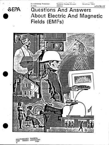
CHAPTER 3aSchnitt A–B3123dmgABFIG. 3.4. Parallel-plate ionization chamber. 1: the polarizing electrode. 2: the measuringelectrode. 3: the guard ring. a: the height (electrode separation) of the air cavity. d: thediameter of the polarizing electrode. m: the diameter of the collecting electrode. g: thewidth of the guard ring.voltage and megavoltage X ray beams and in the dosimetry of b rays, and lowenergy X rays. They can also be used in absolute radiation dosimetry whendirectly embedded into a tissue equivalent phantom. The cavity perturbationfor electrons can be eliminated by making measurements as a function of thecavity thickness and then extrapolating to zero thickness. Using this chamber,the cavity perturbation for parallel-plate chambers of finite thickness can beestimated.80
RADIATION DOSIMETERSSource holderCollecting electrodeOuter electrode (HV)InsulatorTo electrometerFIG. 3.5. Basic design of a brachytherapy well type chamber.3.4. FILM DOSIMETRY3.4.1.Radiographic filmRadiographic X ray film performs several important functions indiagnostic radiology, radiotherapy and radiation protection. It can serve as aradiation detector, a relative dosimeter, a display device and an archivalmedium.Unexposed X ray film consists of a base of thin plastic with a radiationsensitive emulsion (silver bromide (AgBr) grains suspended in gelatin) coateduniformly on one or both sides of the base.Ionization of AgBr grains, as a result of radiation interaction, forms alatent image in the film. This image only becomes visible (filmblackening) and permanent subsequently to processing. Light transmission is a function of the film opacity and can be measuredin terms of optical density (OD) with devices called densitometers. The OD is defined as OD log10 (I0/I) and is a function of dose. I0 is theinitial light intensity and I is the intensity transmitted through the film. Film gives excellent 2-D spatial resolution and, in a single exposure,provides information about the spatial distribution of radiation in thearea of interest or the attenuation of radiation by intervening objects. 81
CHAPTER 3Τhe useful dose range of film is limited and the energy dependence ispronounced for lower energy photons. The response of the film dependson several parameters, which are difficult to control. Consistentprocessing of the film is a particular challenge in this regard. Typically, film is used for qualitative dosimetry, but with propercalibration, careful use and analysis film can also be used for doseevaluation. Various types of film are available for radiotherapy work (e.g. directexposure non-screen films for field size verification, phosphor screenfilms used with simulators and metallic screen films used in portalimaging). Unexposed film would exhibit a background OD called the fog density(ODf). The density due to radiation exposure, called the net OD, can beobtained from the measured density by subtracting the fog density. OD readers include film densitometers, laser densitometers andautomatic film scanners. The principle of operation of a simple film densitometer is shown in Fig. 3.6. Ideally, the relationship between the dose and OD should be linear, butthis is not always the case. Some emulsions are linear, some are linear over alimited dose range and others are non-linear. The dose versus OD curve,known as the sensitometric curve (also known as the characteristic or H&Dcurve, in honour of Hurter and Driffield, who first investigated therelationship) must therefore be established for each film before using it fordosimetry work.A typical H&D curve for a radiographic film is shown in Fig. 3.7. It hasfour regions: (1) fog, at low or zero exposures; (2) toe; (3) a linear portion atLog ratio amplifierIsig2.99FilmI0 FIG. 3.6. Basic film densitometer.82(3½ digits DPM)OD log10 (I0/Isig)
RADIATION DOSIMETERSintermediate exposures; and (4) shoulder and saturation at high exposures. Thelinear portion is referred to as optimum measurement conditions, the toe is theregion of underexposure and the shoulder is the region of overexposure.Important parameters of film response to radiation are gamma, latitudeand speed:The slope of the straight line portion of the H&D curve is called thegamma of the film. The exposure should be chosen to make all parts of the radiograph lie onthe linear portion of the H&D curve, to ensure the same contrast for allODs. The latitude is defined as the range of exposures over which the ODs willlie in the linear region. The speed of a film is determined by giving the exposure required toproduce an OD of 1.0 greater than the OD of fog. Typical applications of a radiographic film in radiotherapy are qualitativeand quantitative measurements, including electron beam dosimetry, qualitycontrol of radiotherapy machines (e.g. congruence of light and radiation fieldsand the determination of the position of a collimator axis, the so called star4(4) ShoulderOD3(3) Linear portion21(1) Fog(2) Toe01101001000Exposure (arbitrary units)FIG. 3.7. Typical sensitometric (characteristic H&D) curve for a radiographic film.83
CHAPTER 3test), verification of treatment techniques in various phantoms and portalimaging.3.4.2.Radiochromic filmRadiochromic film is a new type of film in radiotherapy dosimetry. Themost commonly used is a GafChromic film. It is a colourless film with a nearlytissue equivalent composition (9.0% hydrogen, 60.6% carbon, 11.2% nitrogenand 19.2% oxygen) that develops a blue colour upon radiation exposure.Radiochromic film contains a special dye that is polymerized uponexposure to radiation. The polymer absorbs light, and the transmission of lightthrough the film can be measured with a suitable densitometer. Radiochromicfilm is self-developing, requiring neither developer nor fixer. Since radiochromic film is grainless, it has a very high resolution and can be used in highdose gradient regions for dosimetry (e.g. measurements of dose distributions instereotactic fields and in the vicinity of brachytherapy sources).Dosimetry with radiochromic films has a few advantages over radiographic films, such as ease of use; elimination of the need for darkroomfacilities, film cassettes or film processing; dose rate independence; betterenergy characteristics (except for low energy X rays of 25 kV or less); andinsensitivity to ambient conditions (although excessive humidity should beavoided). Radiochromic films are generally less sensitive than radiographicfilms and are useful at higher doses, although the dose response non-linearityshould be corrected for in the upper dose region.Radiochromic film is a relative dosimeter. If proper care is taken withcalibration and the environmental conditions, a precision better than 3%is achievable. Data on the various characteristics of radiochromic films (e.g. sensitivity,linearity, uniformity, reproducibility and post-irradiation stability) areavailable in the literature. 3.5. LUMINESCENCE DOSIMETRYSome materials, upon absorption of radiation, retain part of the absorbedenergy in metastable states. When this energy is subsequently released in theform of ultraviolet, visible or infrared light, the phenomenon is called luminescence. Two types of luminescence, fluorescence and phosphorescence, areknown, which depend on the time delay between stimulation and the emissionof light. Fluorescence occurs with a time delay of between 10–10 and 10–8 s;84
RADIATION DOSIMETERSphosphorescence occurs with a time delay exceeding 10–8 s. The process ofphosphorescence can be accelerated with a suitable excitation in the form ofheat or light.If the exciting agent is heat, the phenomenon is known as thermoluminescence and the material is called a thermoluminescent material, or a TLDwhen used for purposes of dosimetry. If the exciting agent is light, the phenomenon is referred to as opticallystimulated luminescence (OSL). As discussed in Section 1.4, the highly energetic secondary chargedparticles, usually electrons, that are produced in the primary interactions ofphotons with matter are mainly responsible for the photon energy deposition inmatter. In a crystalline solid these secondary charged particles releasenumerous low energy free electrons and holes through ionizations of atoms andions. The free electrons and holes thus produced will either recombine orbecome trapped in an electron or hole trap, respectively, somewhere in thecrystal.The traps can be intrinsic or can be introduced in the crystal in the form oflattice imperfections consisting of vacancies or impurities. Two types of trap areknown in general: storage traps and recombination centres.A storage trap merely traps free charge carriers and releases them duringthe subsequent (a) heating, resulting in the thermoluminescence process,or (b) irradiation with light, resulting in the OSL process. A charge carrier released from a storage trap may recombine with atrapped charge carrier of opposite sign in a recombination centre(luminescence centre). The recombination energy is at least partiallyemitted in the form of ultraviolet, visible or infrared light that can bemeasured with photodiodes or photomultiplier tubes (PMTs). 3.5.1.ThermoluminescenceThermoluminescence is thermally activated phosphorescence; it is themost spectacular and widely known of a number of different ionizing radiationinduced thermally activated phenomena. Its practical applications range fromarchaeological pottery dating to radiation dosimetry. In 1968 Cameron,Suntharalingam and Kenney published a book on the thermoluminescenceprocess that is still considered an excellent treatise on the practical aspects ofthe thermoluminescence phenomenon. A useful phenomenological model ofthe thermoluminescence mechanism is provided in terms of the band model for85
CHAPTER 3solids. The storage traps and recombination centres, each type characterizedwith an activation energy (trap depth) that depends on the crystalline solid andthe nature of the trap, are located in the energy gap between the valence bandand the conduction band. The states just below the conduction band representelectron traps, the states just above the valence band are hole traps. Thetrapping levels are empty before irradiation (i.e. the hole traps containelectrons and the electron traps do not).During irradiation the secondary charged particles lift electrons into theconduction band either from the valence band (leaving a free hole in thevalence band) or from an empty hole trap (filling the hole trap).The system may approach thermal equilibrium through several means:Free charge carriers recombine with the recombination energy convertedinto heat; A free charge carrier recombines with a charge carrier of opposite signtrapped at a luminescence centre, the recombination energy beingemitted as optical fluorescence; The free charge carrier becomes trapped at a storage trap, and this eventis then responsible for phosphorescence or the thermoluminescence andOSL processes. 3.5.2.Thermoluminescent dosimeter systemsThe TLDs most commonly used in medical applications are LiF:Mg,Ti,LiF:Mg,Cu,P and Li2B4O7:Mn, because of their tissue equivalence. OtherTLDs, used because of their high sensitivity, are CaSO4:Dy, Al2O3:C andCaF2:Mn.TLDs are available in various forms (e.g. powder, chips, rods andribbons). Before they are used, TLDs need to be annealed to erase the residualsignal. Well established and reproducible annealing cycles, including theheating and cooling rates, should be used. A basic TLD reader system consists of a planchet for placing and heatingthe TLD, a PMT to detect the thermoluminescence light emission and convertit into an electrical signal linearly proportional to the detected photon fluenceand an electrometer for recording the PMT signal as a charge or current. Abasic schematic diagram of a TLD reader is shown in Fig. 3.8.86
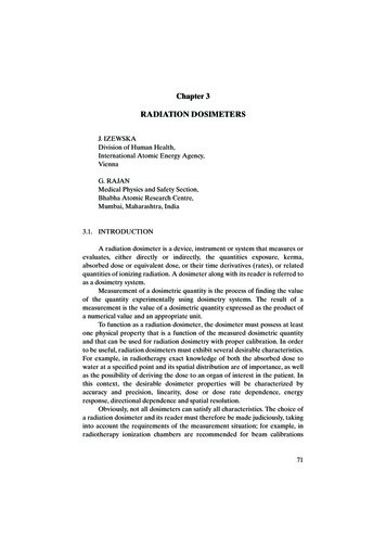
RADIATION DOSIMETERSElectrometerHVThermoluminescence chargePMTTLDHeaterFIG. 3.8. TLD reader.The thermoluminescence intensity emission is a function of the TLDtemperature T. Keeping the heating rate constant makes the temperatureT proportional to time t, and so the thermoluminescence intensity can beplotted as a function of t if a recorder output is available with the TLDmeasuring system. The resulting curve is called the TLD glow curve. Ingeneral, if the emitted light is plotted against the crystal temperature oneobtains a thermoluminescence thermogram (Fig. 3.9). The peaks in the glow curve may be correlated with trap depthsresponsible for thermoluminescence emission. The main dosimetric peak of the LiF:Mg,Ti glow curve between 180ºCand 260ºC is used for dosimetry. The peak temperature is high enough soas not to be affected by room temperature and still low enough so as notto interfere with black body emission from the heating planchet. The total thermoluminescence signal emitted (i.e. the area under theappropriate portion of the glow curve) can be correlated to dose throughproper calibration. Good reproducibility of heating cycles during the readout is important foraccurate dosimetry. The thermoluminescence signal decreases in time after the irradiationdue to spontaneous emission of light at room temperature. This process iscalled fading. Typically, for LiF:Mg,Ti, the fading of the dosimetric peakdoes not exceed a few per cent in the months after irradiation. The thermoluminescence dose response is linear over a wide range ofdoses used in radiotherapy, although it increases in the higher doseregion, exhibiting supralinear behaviour before it saturates at even higherdoses. 87
Normalized thermolumescence signalCHAPTER 31.0Time after irradiation0.81h4d20 d0.60.40.20.0050100150200250300350400Temperature ( C)FIG. 3.9. A typical thermogram (glow curve) of LiF:Mg,Ti measured with a TLD readerat a low heating rate
Therapy dosimeters are generally used in the same geometry as that in which they are calibrated. 3.2.6. Spatial resolution and physical size Since the dose is a point quantity, the dosimeter should allow the determi-nation