Transcription
BRESIDENTIALADDITIONCOMMUNITY DEVELOPMENT DEPARTMENT—345 N. EL DORADO STREET—STOCKTON, CA 95202—(209) 937-8561www.stocktongov.com/CDD/buildingNOTE: Check with your homeowners’ association and architectural review committee for Conditions, Covenants & Restrictions (CC&R’s). The City ofStockton has no regulatory authority to enforce or notify permit applicants of CC&R requirements, nor deny permits for non-compliance.DESIGN CRITERIA / APPLICABLE CODES Seismic Design Category: DBasic wind speed: 110 mph, Exposure CClimate Zone 12Codes: 2013 CRC: California Residential Code2013 CPC: California Plumbing Code2013 CMC: California Mechanical Code2013 CEC: California Electrical Code2013 CEC: California Energy Code2013 CGBSC: CA Green Building Standards CodeCity of Stockton Municipal CodeDRAWING CRITERIA It is preferred that drawings be limited in size to aMINIMUM of 18"x24" and a MAXIMUM of 30"x42" Plans must be clear, complete, and legible; illegibleor incomplete plans will not be accepted. Preferred scale: 1/4 inch per foot for structural andarchitectural; 1 inch 20 feet for site plansWHAT’S INCLUDED IN THIS HANDOUTPage1. Submittal Checklist and Requirements . 22. Information Required on Plan Submittals . 33. Main Building Setbacks and Lot Coverage Requirements . 44. Requirements for Additions Located in a Special Flood Hazard Area . 5-75. Required Inspections . 86. Sample Site Plan . 97. Sample Floor Plan . 108. Natural Light and Ventilation Requirements and Sample Analysis . 119. Smoke Detectors, Electrical Receptacles, Switches and Fixtures . 1210. Overview of Title 24 Residential Lighting Standards . 1311. Illustration of Title 24 Requirements for Residential Lighting . 1412. Prescriptive Energy Standards for Room Additions . 1513. Construction Details:A. Attachment of New Footing to Existing Footing . 16B. Wall Section with Raised Floor . 17C. Wall Section with Slab Floor Footing . 18D. Span Tables/Allowable Loads (Ceiling Joist, Floor Joist and Rafters) . 19E. Header Spans Table (Table R502.5(1), California Residential Code) . 20-21F. Typical Blocking Detail and Roof Joist Load Paths. 22G. Conventional Wall Bracing (CRC Section R602.10.4) and diagrams . 23H. Alternate Braced Wall (ABW) & Portal Frames with hold downs. 24I. Braced Wall Panel/Methods/Materials/Min. Length/Required Adjusted Length . 25J. Fastening Schedule (Table 2304.9.1, California Building Code) . 26-27Last Revised 6/29/15Page 1 of 27
SUBMITTAL CHECKLIST Incomplete submittals will not be accepted Plan check fees are to be paid at the time of submittal Due to the complex nature of navigating all the different building code requirements fornew construction it is strongly recommended that a design professional (e.g. residentialdesigner, Architect/Engineer) be hired to provide construction plans for permit issuance. Final two sets of plans must be wet-signed by preparer on each page.Architect/Engineer must affix their seal and wet-sign. Cover sheet of supportingdocuments also to be wet- signed. Project address must be on each sheet.SUBMITTAL DOCUMENTS CHECKLISTCOMPLETED BUILDING PERMIT APPLICATIONCOVER SHEET (3)SITE PLAN (3)FLOOR PLAN (3)ELEVATIONS (3)ARCHITECTURAL & STRUCTURAL SHEETS (3 sets)PLUMBING/MECHANICAL/ELECTRICAL SHEETS (3 sets)STRUCTURAL CALCULATIONS (2 sets)TRUSS CALCULATIONS (2 sets, if applicable)TITLE 24 ENERGY DOCUMENTS (2 sets)GRADING PLAN (2 sets, if applicable)FLOOD ELEVATION CERTIFICATE (if applicable)THE FOLLOWING ADDITIONAL ITEMS MAY BEREQUIRED BASED ON PROJECT TYPE, SCOPE,AND/OR LOCATION: School District certificate of fees paid (additions of 500 sq. ft. and over)Special Inspection AgreementSoils ReportElectrical Load CalculationsPlumbing CalculationsSEPARATE PERMITS AND PLANS ARE REQUIREDFOR THE FOLLOWING TYPES OF WORK: Pools and spasAccessory structures proposed on the plot planLast Revised 6/29/15Page 2 of 27
INFORMATION REQUIRED ON PLAN SUBMITTALSCOVER SHEET:TRUSS PLANS & CALCULATIONS (if applicable): Truss layout plan with truss member identificationcorresponding to each truss Connection details Legal address of project siteAssessor’s Parcel Number (APN)Name, address, phone number of owner, contractorand contact personName, address, phone number, title and registrationinformation of project design professionalWritten description of work to be undertakenCurrent applicable codes and edition datesOccupancy classification and type of constructionZoningGross square footage area by floorSITE PLAN (see sample on pg. 7): North arrowLot dimensions & boundaries, showing entire parcelScale usedLegal address of job siteExisting and proposed structures, including solidcovered patios, porches, sheds, etc., and their areas insquare feet and number of storiesDistances of structures from property lines and otherstructuresUtility lines and connection points (water, sewer,electrical, gas, cable, fire hydrants, etc.)Adjoining streetsDriveways and parking areasAll easementsFence bollards, barriers or walls; indicate material ofconstruction and height Signature of preparer (two copies must be wetstamped)Special Flood Hazard Area boundary line (ifentire property not within a single flood zone)Roof plan; show eaves, overhangs, rakes and gables, sizeof rafters, sheathing material, roofing material, etc. A cross-section of each structural system, detailing allstructural connections Structural second-floor, ceiling-joist, and rafter plansPLUMBING, MECHANICAL &ELECTRICAL SHEETS: Windows, doorsRooftop equipmentLocation of all mechanical units, ducts, and registersLocation of all electrical outlets, switches, lights, arcfault and G.F.C.I. outlets, smoke detectors, and ser- viceand sub-panel locations and sizesCF1R-ADD-02 form with required signatures if addition isunder 1,000 square feet; ORCF1R-ADD-01 form with required signatures if addition isover 1,000 square feet; ORCF1R-PRF-01 forms with required signatures if utilizing theperformance approachIntegrate required energy forms into plansHeating/cooling calculations and equipment listings (ifapplicable)GRADING PLAN (if required): Types of siding and roofing materialsDimensions of all elements, including height ofstructuresLocation of all plumbing fixturesTITLE 24 ENERGY DOCUMENTS: Details to include:attachment, and dimensions of members ELEVATIONS SHALL SHOW ALLSIDES OF BUILDING, INCLUDING:Structural systems and materials listing Fireplace: masonry Post and girder intersections If applicable, stairway rise and run, framing,FLOOR PLAN (see sample on pg. 8):Dimensions and use of all existing and proposedrooms and/or areas inside buildingsFoundation and structural floor framing plans; includedetails of footings, piers, and grade beamsArchitectural floor plan(s), dimensioned, will all openingslisted as to size and operation. If it is an addition, show allrooms adjoining the new addition and their window sizes Patios, walkways, existing and proposed sidewalksProposed pad and finished floor elevationsProject designer approvalARCHITECTURAL & STRUCTURALPLANS:Index of drawingsFlood zone identificationLateral bracing details Existing and proposed grading plansPad elevations ground slope drainage scheme andtopographic plan drawn to 1'-0" contoursRetaining walls and drainage systems, existing andproposedBase Flood Elevation, all floor elevations (if applicable)Last Revised 6/29/15Page 3 of 27
SETBACK AND LOT COVERAGE REQUIREMENTSThis overview is provided for your reference only. Prior to building any structure or making an addition ormodification to any existing structure, check with the Community Development Department at (209) 9378561 regarding minimum required distances from property lines and other structures, as well as findingthe location of any easements.LOT COVERAGE:The maximum area of a lot that may be covered by all primary and accessory structures over 30 inches inheight (house, patio, garage, carport, sheds, etc.) is fifty (50) percent for residential zones.PROPERTY LINE:Contact the Planning Division for property line setbacks. The back edge of the sidewalk is NOT necessarily theproperty line. The property line is normally 2 feet in back of the sidewalk.DRIVEWAYS:Driveways shall not be located within 20 feet of a right-of-way, measured from the property line and shall notexceed 26 feet in width. Driveways shall be paved with a permanent surface, consisting of concrete, asphalt,or other similar material. Gravel is not considered an acceptable surface.LOT TYPES:Last Revised 6/29/15Page 4 of 27
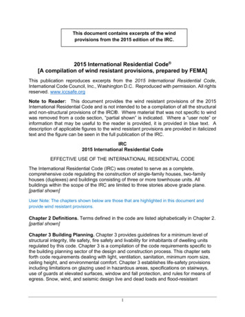
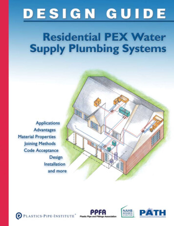
CHART 1 - REQUIREMENTS FOR ADDITIONS IN A SPECIAL FLOODHAZARD AREA (SFHA)Buildings in all Flood ZonesLateral Addition ONLYAdditionONLY?NOWork involvesaddition ANDother work on theBase BuildingChart 2YESDate ofBaseBuildingPreFIRMNOYESLast Revised 6/29/15NOStructurallyConnected?YESAddition requiredto comply; BaseBuilding requiredto complyNOAddition notrequired to comply A Zone: Addition required to comply V Zone: Addition shall comply; BaseBuilding shall comply (otherwise itbecomes an “obstruction” and thusmakes the addition non-compliant withthe free-of-obstruction requirement) A Zone: Addition requiredto comply to at least LFE ofBase Building V Zone: Addition requiredto ntialImprovement?SubstantialImprovement?Addition requiredto complyAddition and BaseBuilding required tocomply“Substantial improvement” means anyreconstruction, rehabilitation, addition, or otherimprovement of a structure, the cost of whichequals or exceeds 50 percent of the marketvalue of the structure before the “start ofconstruction” of the improvement. This termincludes structures which have incurred“substantial damage,” regardless of the actualrepair work performed. [SMC 15.44.040]Page 5 of 27
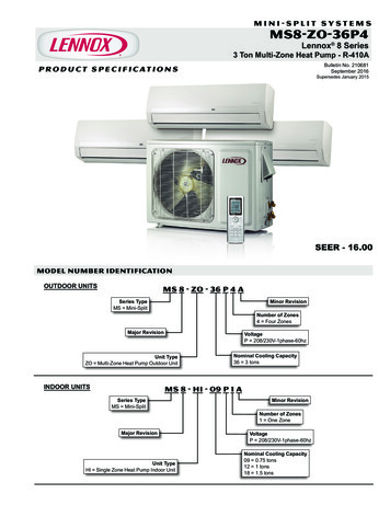
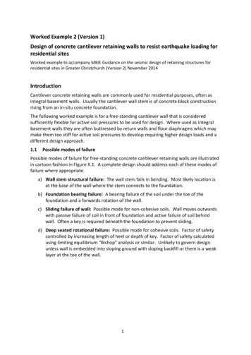
CHART 2 - REQUIREMENTS FOR ADDITIONS IN A SPECIAL FLOODHAZARD AREA (SFHA)Buildings in all Flood ZonesLateral Addition AND Other Improvements in BaseBuilding (e.g., rehab, renovate, remodel)Date ofBaseBuildingPreFIRMYESAddition requiredto; Base Buildingshall comply basedon Flood provement?Work not requiredto complyNOAll work required to complybased on Flood Zone and shallnot be allowed to make theBase Building non-compliantYESAll work requiredto comply basedon Flood Zoneand effective BFELast Revised 6/29/15“Substantial improvement” means anyreconstruction, rehabilitation, addition, or otherimprovement of a structure, the cost of whichequals or exceeds 50 percent of the marketvalue of the structure before the “start ofconstruction” of the improvement. This termincludes structures which have incurred“substantial damage,” regardless of the actualrepair work performed. [SMC 15.44.040]Page 6 of 27
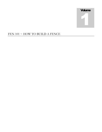
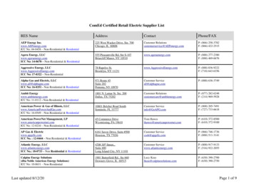
EXAMPLES OF ADDITIONS LOCATED IN A SPECIAL FLOODHAZARD AREA (SFHA)These figures are from FEMA P-758, Substantial Improvement /Substantial Damage Desk Reference.Last Revised 6/29/15Page 7 of 27
REQUIRED INSPECTIONSWhen you are ready for an inspection, call the Building Safety Division’s 24-hour inspection recorder at(209) 937-8560. You will be asked to leave your permit number, job site address, type of inspection beingrequested, date for which you wish to schedule the inspection, and your contact information. Please speakslowly and clearly. Requests left by 4:00 p.m. will be scheduled for the next business day; requests left after4:00 p.m. will be scheduled for the second following business day.The approved set of plans, including structural calculations, truss calculations, and/or energy calculations,must be on-site for each inspection. The Inspection Record card must be posted for the inspector’ssignature.If the inspector approves the work, the Inspection Record card will be initialed and dated. If the work is notapproved, the inspector will leave a correction notice stating which corrections are needed. It is the permitholder’s responsibility to make the required corrections and request a re-inspection of the work.THE TYPICAL ORDER OF ON-SITE INSPECTIONS IS AS FOLLOWS:1. UNDER-SLAB PLUMBING:7. INSULATION INSPECTION:Drain lines must be plugged and filled with water through a10' vertical riser. Water lines must be tested with a pressureof 50 psi or City water street pressure for a minimum of 15minutes. Property lines should be clearly marked.Only certified or approved insulation may be installed. All gapsaround windows and penetrations through plates must besealed with foam sealant. Underfloor must be accessible toinspector and insulation certificate must be on-site.2. FOUNDATION:8. SHEETROCK NAILING INSPECTION:Trenches must be excavated and reinforcing in place.Forms erected and hold-downs held in place. Propertylines should be clearly marked.Prior to taping and texturing, all sheetrock must be in place andmust be inspected and approved. Walls of bathtub/ showerareas must have moisture-resistant sheetrock. Gas linesshould be pumped to 15 lbs.3. SLAB INSPECTION:9. LATH INSPECTION:Gravel, compacted sand or soil must be in place. Mesh orreinforcement must be placed over moisture barrier ifrequired. Pipes penetrating slab must be protected fromexpansion and breakage.Sheetrock must be installed prior to lath inspection. All tears andholes in lath must be patched or sealed.4. UNDERFLOOR INSPECTION:Prior to installation of floor sheathing, the drain lines must beplugged and filled with water through a 10' vertical riser.Water lines must be tested with a pressure of 50 psi or Citywater street pressure for a minimum of 15 minutes. Gas linesmust be tested to hold a pressure of 10 psi for 15 minutes.The mechanical duct system must be installed and insulated.All floor framing must be in place.5. DIAPHRAGM & ROOF NAILING:If the building has shear panels (walls, roof, floor) a nailinginspection is required prior to covering. All metal connectorsmust be installed. Plans to state exact size and spacing ofnails. Trusses should be completed and ready for inspectionat the time of the roof nail inspection and truss plans on thejob site. All framing should be completed prior to schedulingthis inspection.6. ROUGH FRAME INSPECTION:All rough plumbing, mechanical and electrical must becomplete. Windows, roofing and siding installed (stucco lathinstalled without stucco). No insulation can be installed.10. FINAL INSPECTION:Structure must be completely finished and ready for occupancy.Electric service must be energized.11. ELECTRIC METER TAGGING:(If upgrading service)Method of grounding (Ufer) must be visible for inspection. If noUfer ground available, must install two (2) 5/8" ground rodsspaced a minimum of six feet apart. When approved, theinspector will leave a clearance tag on/in the panel box and a cardfor the applicant to fax to PG&E.*12. GAS METER TAGGING:The gas test must be approved prior to requesting a gas tag. Atleast one appliance must be installed. If approved, the inspectorwill leave a clearance tag on the gas line at the meter location andwill give the applicant a PG&E clearance card. A clearance tag willnot be issued unless the building has received a final inspectionapproval or an application for “Temporary Clearance forConnection of Utilities” has been submitted and approved. Thesubmittal for “Temporary Clearance for Connection of Utilities”must comply with the utility release policy and must beaccompanied by a letter stating the reason for the early release ofthe gas utility.*Release forms may be faxed to: (800) 700-5722Last Revised 6/29/15Page 8 of 27
SAMPLE SITE PLANN ?PROPERTY LINE10' SSJID Y LINE?PROPERTY LINE?DRIVEWAY10' PUBLIC UTILITY EASEMENTPROPERTY LINEHOUSE NUMBER AND STREET NAME1) Show lot dimensions and total square footage of all covered areas.2) Check with the Planning Division for building setback requirements.3) Check with Public Works for location of any utility easements.Last Revised 6/29/15Page 9 of 27
SAMPLE FLOOR PLANCONCRETE STOOP3'-0"EXISTING WALL (TO BE REMOVED)EXISTING WALL (TO REMAIN)NEW WALLLEGEND:GFI/wp50x68 SLIDING GLASSDOOR DUAL GLAZED(E) 40x40 HS(E) KITCHEN10' x 12'S24x68120V SMOKE DETECTORW/BATTERY BACKUP27'-6"120V SMOKE DETECTORW/BATTERY BACKUP19'-0"S12'-0" MAX.6'-0" MAX.(N) MASTER BEDROOM12' x 18'-8"36" MIN.(E) FAMILY ROOM14' x 14'2'-9"(2) 3' WARDROBE DOORSFLUORESCENT LIGHTGFISS(N) MASTER BATH12' x 5'-4"5'-9"24x68EXHAUSTFFANGFI(E) 40x40 HS30" MIN.16'-0"EXISTINGADDITIONScale: 1/4" 1'-0"Last Revised 6/29/15Page 10 of 27
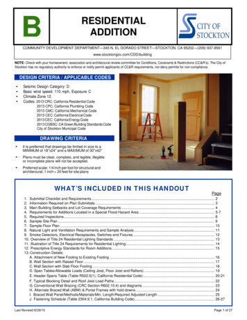
NATURAL LIGHT AND VENTILATION REQUIREMENTS(Windows, Doors and Skylights)NATURAL LIGHT:Habitable rooms within a dwelling unit shall be provided with natural light by means of exterior glazed openingswith an area not less than 8% of the floor area of such rooms with a minimum of twenty-five (25) square feet.(2013 CRC R303.1)VENTILATION:Habitable rooms within a dwelling unit shall be provided with natural ventilation by means of openable exterioropenings with an area of not less than 4% of the floor area of such rooms with a minimum of twenty-five (25)square feet. (2013 CRC R303.1)ROOMS ADJOINING PROPOSED ADDITION:If there are windows and doors that are affected by the addition, rooms adjoining the addition need to be reviewedfor lighting and ventilation requirements the same as for new construction.NOTE: Provide floor plans of rooms adjoining the addition. Indicate any windows and doors (including their sizesand method of opening) which are affected by the addition.SAMPLE ANALYSISLEGEND:EXISTING WALL (TO BE REMOVED)EXISTING WALL (TO REMAIN)NEW WALLPROPOSED ADDITION: 12'x24' 288 SQ. FT.LIGHTING REQUIREMENT:288 SQ. FT. x .08 . 23.04 SQ. FT.VENTILATION REQUIREMENT:(E) 40x40 HS288 SQ. FT. x .04 . 11.52 SQ. FT.(N) 50x68 SLIDING GLASSDOOR DUAL GLAZEDPROPOSED LIGHTING:5' x 4' 5' x 6.67 53.35 SQ. FT. . 23.04 SQ. FT. OK!PROPOSED VENTILATION:2.5' x 4' 2.5' x 6.67 26.68 SQ. FT. . 11.52 SQ. FT. OK!(E) KITCHEN10' x 12'(E) 40x48 TOBE REMOVEDEXISTING KITCHEN: 10'x12' 120 SQ. FT.PROPOSEDADDITION12' x 24'LIGHTING REQUIREMENT:120 SQ. FT. x .08 . 9.6 SQ. FT.VENTILATION REQUIREMENT:120 SQ. FT. x .04 . 4.8 SQ. FT.(E) WINDOW:LIGHTING: 4' x 4' 16 SQ. FT. 9.6 SQ. FT. OK!VENTILATION: 2' x 4' 8 SQ. FT. . 4.8 SQ. FT. OK!(E) 20x40 TOBE REMOVEDEXISTING FAMILY RM: 14'x14' 196 SQ. FT.(E) FAMILY ROOM14' x 14'LIGHTING REQUIREMENT:196 SQ. FT. x .08 . 15.68 SQ. FT.VENTILATION REQUIREMENT:196 SQ. FT. x .04 . 7.84 SQ. FT.(E) WINDOW:LIGHTING: 4' x 4' 16 SQ. FT. 15.68 SQ. FT. OK!VENTILATION: 2' x 4' 8 SQ. FT. . 7.84 SQ. FT. OK!(E) 20x40 TOBE REMOVED(E) 40x40 HSLast Revised 6/29/15(N) 50x40 HSBased on these calculations, no additional windowsor enlarging of the existing window is required.Page 11 of 27
Smoke Detectors and Carbon Monoxide Detectors Smoke detectors shall be installed in every sleeping room, in the hallway outside anysleeping room and on every story including basements and habitable attics. Smoke detectors in new bedrooms or hallways must be connected to the house wiring and must also have a battery backup. They shall be interconnected when accessible. Carbon Monoxide detectors are required outside sleeping area and on every story.These detectors are also to be interconnected. Multi-purpose alarms are allowed ifapproved by the State Fire Marshal. Show locations of smoke and carbon monoxide detectors on the plans.ELECTRICAL RECEPTACLES, SWITCHES & FIXTURESShow locations of all electrical receptacles, switches, and fixtures.A. Receptacles must be spaced not more than 12 feet apart, with the first outlet not more than six (6) feetfrom the door, fireplace, or similar opening. Every wall section at least two (2) feet wide or greater requires at least one receptacle.B. At least one receptacle outlet shall be installed in hallways ten (10) feet or more inlength.C. The following Receptacles shall be GFI-protected:All receptacles in BathroomsAll kitchen counter receptaclesAll exterior receptaclesAll receptacles in garages or accessory buildings that have a floor at or below grade level.All receptacles in crawl spaces or unfinished basements at or below grade level.Any other receptacle within 6’ of a sink.D. Receptacles in kitchens and dining areas shall be installed at each counter space so that no pointalong the wall line is more than 24 inches, measured horizontally from a receptacle outlet in thatspace. Island and peninsular counter tops 12 inches or wider shall have at least one receptacle.E. All rooms, halls, and exterior doors must have a switch controlling a light fixture or receptacle.F. Arc Fault protection is required everywhere not Ground fault protected.G. All receptacles shall be tamper resistant. CEC 406.11HIGH-EFFICACY GENERAL LIGHTINGProvide high-efficacy general lighting throughout (see exceptions in the CEC 150(k). Highefficacy lighting shall be at least 30 lumens per watt (see Table 150-C) be switched separately and shall be controlled by the most accessible switch location.Refer to the information on the following two pages for information on California's Title 24Residential Lighting Standards.Last Revised 6/29/15Page 12 of 27
OVERVIEW of 2013 TITLE 24 LIGHTING STANDARDSHigh-efficacyORUp to 50% of total wattage can be low-efficacy (incandescent)KitchenAll high-efficacy and low-efficacy lighting must be switched separatelyBathroomGarageLaundry RmUtility RmBathroom—At least one high efficacy luminaire and all low efficacy lightingmust be controlled by vacancy sensors.Garage, Laundry Rm & Utility Rm—All must be high efficacy and must be controlled by vacancy sensors.All OtherInteriorRoomsHigh-efficacyORLow-efficacy if controlled by vacancy sensor or by a dimmer.(Living Room,Bedrooms, Dining Room, Hallways) exceptclosets less than70 sq. ft.Outdoorlightingattached tobuildingsHigh-efficacyORLow-efficacy if controlled by a motion-sensor and controlled by one of these:Photo control, astronomical time clock or energy management controlsystem (EMCS)FOR ALL APPLICATIONS: Electronic ballasts for all fluorescent lamps rated 13 watts or greater Recessed luminaires in all insulated ceilings approved for zero-clearance insulation cover (IC) and certified airtight ASTM E283HIGH-EFFICACY FIXTURESLamp PowerMinimum EfficacyCompliantCompliantLumens per WattIndoor LampsOutdoor Lamps5 Watts or Less30 lm/W Compact Fluorescent Metal Halide HPS Fluorescent Compact Fluorescent 5 Watts to45 lm/W Compact Fluorescent Metal Halide HPS15 Watts Fluorescent Compact Fluorescent 15 Watts to60 lm/W Compact Fluorescent Metal Halide HPS40 watts Fluorescent Compact FluorescentOver 40 watts90 lm/W Compact Fluorescent Metal Halide HPS Fluorescent Compact FluorescentLast Revised 6/29/15Note: High-efficacy luminaires may notcontain medium screw-base sockets. Exception: outdoor metal halideor high-pressure sodium (HPS) highintensity discharge luminaires withelectromagnetic ballast may havemedium screw-base sockets if minimum efficacy and motion-sensor/photo-control requirements are met.Page 13 of 27
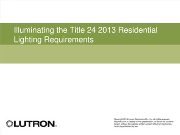
Last Revised 6/29/15Page 14 of 27Outdoor fixtures attachedto building must be highefficacy or controlled bymotion-sensor with photo-controlHardwired fixtures ingarages must be highefficacy or be controlledby a manual-on, automatic-off occupancy sensorNote: Title 24 requirements do not apply toportable floor lamps ortable lampsHardwired fixtures in "otherinterior rooms" must be highefficacy or be controlled by amanual-on, automatic-offoccupancy sensor or dimmerHardwired fixtures inbedrooms must be highefficacy or be controlledby a manual-on, automatic-off occupancy sensoror a dimmerTitle 24 Requirements for Residential LightingHardwired fixtures inutility rooms must behigh-efficacy or be controlled by a manual-on,automatic-off sensorSeparate switches forhigh-efficacy and lowefficacy fixtures arerequired in kitchenLighting fixtures in kitchen area must be highefficacy although up to50% of total wattage inkitchen may be otherthan high-efficacy fixturesHalo recessed lightingH270 Series meets highefficacy requirements inall areas of the houseHardwired fixtures inbathrooms must behigh-efficacy or be controlled by a manual-on,automatic-off occupancy sensorRecessed fixtures ininsulated ceilings mustbe IC rated and AIR-TITEcertified
PRESCRIPTIVE ENERGY STANDARDS FOR ROOM ADDITIONSREQUIREMENTS FORADDITIONS OF 400 sq. ft.REQUIREMENTS FORADDITIONS OF 400 TO 700 sq. ft.REQUIREMENTS FORADDITIONS OF 700 sq.ft.1BUILDING INSULATIONBUILDING INSULATIONBUILDING INSULATIONCeiling R-38 (U .025)Walls R-13(2x4)/R-19(2x6)Crawl Space R-19 (U .037)Window U 0.32 (Low E)SHGC 0.25Ceiling R-38 (U .025)Walls R-13(2x4)/R-19(2x6)Crawl Space R-19 (U .037)Window U 0.32 (Low E)SHGC 0.25Ceiling R-38Walls R-15 R4 or R-13 R5Crawl Space R-19 (U .037)Window U 0.32 (Low E)SHGC 0.25Radiant Barrier Required(Above Attic Spaces)Radiant Barrier Required(Above Attic Spaces)Radiant Barrier Required(Above Attic Spaces)HEATING & COOLING*HEATING & COOLING*HEATING & COOLING*AFUE 80%SEER Rating 14 SEEREER 12.2Duct Sealing Required****AFUE 80%SEER Rating 14 SEEREER 12.2Duct Sealing Required****AFUE 80%SEER Rating 14 SEEREER 12.2Duct Sealing Required****Refrigerant Charge or ChargeIndicator Display—Required *Refrigerant Charge or ChargeIndicator Display—Required**Refrigerant Charge or ChargeIndicator Display—Required**MAXIMUM GLAZINGMAXIMUM GLAZINGMAXIMUM GLAZING(Dual Glaze)(Dual Glaze)(Dual Glaze) 75 sq. ft. or30% x CFA, whicheveris greater 120 sq. ft. or25% x CFA, whicheveris greater 175 sq. ft. or20% x CFA, whicheveris greaterWEST ORIENTATIONGLAZING MAXIMUMWEST ORIENTATIONGLAZING MAXIMUM60 sq.ft.70 sq.ft. or 50% x CFA,whichever is greaterWEST ORIENTATIONGLAZING MAXIMUM60 sq.ft.CFA—Conditioned Floor AreaCFA—Conditioned Floor AreaCFA—Conditioned Floor AreaCool Roof - Steep Sloped ( 2:12):Aged Solar Reflectance 0.20 ; Thermal Emittance 0.75 (Exception: Addition 300 sq.ft.)Water Heater—Minimum Energy FactorGas Storage 55 gallons : Currently 0.67 - (.0019 x storage volume)(40 gal 0.594 EF and 50 gal 0.575 EF)* If heating and cooling system is left unchanged, compliance with the standards is not required.** If more than 40 feet of new or replacement ducts are installed in unconditioned space, duct testingis required.1 Additions 1000 sq. ft.: Package A Whole House Fan.Last Revised 6/29/15Page 15 of 27
ATTACHMENT OF NEW FOOTING TO EXISTING FOOTING1/2" DIAMETER REBAR @ 48"SPACING WITH 6" EMBEDMENTINTO 3/4" DIAMETER DRILLEDHOLE SET WITH EPOXY(N) 3-1/2" THICK SLAB REINFORCEDWITH A MINIMUM OF 6" x 6" NO. 10GAUGE WELDED WIRE REINFORCINGMESH12"6"(E) CONCRETEFOUNDATIONSEE PLAN(N) CONCRETE FOUNDATION(N) FOUNDATIONLast Revised 6/29/15(E) FOUNDATIONPage 16 of 27
RAISED-FLOOR CONSTRUCTION SECTIONA. ROOF COVERING ON 15# FELT PAPER ON PLYWOOD OR1" x 4" SKIP SHEATHING (WOOD SHAKE OR WOOD SHINGLEONLY). PLYWOOD EDGE NAIL 8d @ 6" O.C." THICK, SHEATHINGABEDGE NAILB. MANUFACTURED TRUSSES OR RAFTERS.IF TRUSSES ARE USED, PROVIDE TRUSS CALCULATIONS.RAFTERS: 2" x " @ O.C.(REFER TO ALLOWABLE SPAN FOR RAFTERS)CDWINDOW ORDOOR HEADEREFC. BLOCKING OR EAVE VENTS WITH 16d NAILS @ 8" O.C.TO DBL. TOP PLATE (Drill for venting as required)D. MINIMUM REQUIRED INSULATION OR BETTER.CEILING: R- , WALL: R- ,FLOOR: R- (SEE "PRESCRIPTIVE ENERGYSTANDARDS" PAGE FOR REQUIRED INSULATION)(Maintain 1” air space between insulation & roof deck)E. CEILING JOIST
Overview of Title 24 Residential Lighting Standards . 13 11. Illustration of Title 24 Require ments for Residential Lighting . 14 12. Prescriptive Energy Standards