Transcription
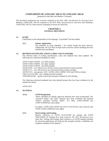
Mv SERIES (360 psi)Clean Agent Fire Suppression SystemFor Use With 3M Novec 1230 Fire Protection FluidThe Janus Fire Systems Mv Series Clean Agent Fire Suppression System utilizes 3M Novec 1230 Fire Protection Fluid as the extinguishing medium. Novec 1230 fluid is a clear, colorless andlow odor liquid perfectly suited to protect high value assets in areas that may be normally occupied,in locations where clean-up of other agents is problematic, when storage space for a fire suppression agent is restricted, or when an electrically non-conductive agent is required. Each systemconsists of the following components and their associated accessories:1. Agent Storage Components - Storage components consist of the cylinder assembly(s), whichcontains the Novec 1230 fluid, and the cylinder bracket(s), which holds the cylinder assemblysecurely in place.2. Agent Fluid Distribution Components - Distribution components consist of the dischargenozzles used to introduce the Novec 1230 fluid into a protected hazard along with the associated piping system used to connect the nozzles to the cylinder assembly.3. Trim Components - Trim components complete the installation of the suppression system andconsist of connection fittings, pressure gauge, low-pressure supervisory switch, electric valveactuator, and manual valve actuator.4. Slave Arrangement Components - Slave arrangement components consist of the pneumaticvalve actuator(s), actuation check valve, vent check, actuation hose, and fittings required for amultiple cylinder (slave) arrangement.5. Supplemental Components - Supplemental components include the discharge pressureswitch and manifold check valve. They supplement the core equipment or complete a specificmulti-cylinder configuration.6. Control Panel - This device monitors the condition of the electric actuator, detectors, warningdevices, cylinder pressure, and any manual release and abort stations. All electric or electronicdevices must connect to the control panel in order to function.7. Detection and Alarm Devices - Detection devices coupled with manual release and abortstations maximize system efficiency while audible and visual alarm devices alert staff of alarmconditions.Typical Clean Agent System LayoutAlarmWarning SignElectricValveActuatorSmoke DetectorCylinder ValveDischarge NozzleControl PanelManual Release& AbortCylinder BracketAgent Storage CylinderDS1116Revised: 06-Feb-2015 2010 Janus Fire Systems. All rights reserved (6/2010) Janus Design Suite and Janus Fire Systems are registered trademarks of Janus Fire Systems.Novec and 3M are trademarks of 3M Company.
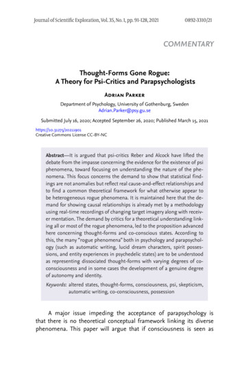
EQUIPMENT DESCRIPTIONThe Novec 1230 fluid is stored as a liquid in cylinder assemblies designed specifically for the application and charged to a fill density of between 35 lb/ft3 (561 kg/m3) and 70 lb/ft3 (1121 kg/m3). Toensure optimal performance, each cylinder is superpressurized with dry nitrogen to 360 psi (24.8bar) at 70 F (21 C). An identification label is affixed to the cylinder body indicating the fill quantity ofNovec 1230 fluid, charging pressure, date of fill, and fill station. The Mv Series supports two cylindercapacities.Fire suppression systems utilizing Novec 1230 fluid are designed to be discharged within 10 secondsinto a room, area, or enclosure with the structural integrity to retain the agent. The Novec 1230 fluiduniformly mixes throughout the protect area achieving a minimum concentration level in accordancewith NFPA 2001 and/or agency listings.Fill CapacityNominalCylinderSizeP/N250 lb20506420 9126.6The cylinder assembly is composed of a cylinder, dip tube, cylinder valve, and liquid level indicator.Cylinder ValveDip 116Revised: 06-Feb-2015Cylinder Valve: The automatic release of Novec 1230fluid is controlled by a forged brass, differential pressure operated cylinder valve connected to the neckof the cylinder. The valve assembly is shipped withan anti-recoil safety device installed in the dischargeoutlet and chained to the cylinder valve.Dip Tube: A threaded, rigid dip tube extends from thecylinder neck down to its bottom.Cylinder: The light walled, welded seam cylinder ismanufactured according to the requirements of theU.S. Department of Transportation (USDOT) andTransport Canada (TC) for compressed gas. Internalneck threads allow connection of the cylinder valve.The cylinder is designed for mounting in a vertical position only.Liquid Level Indicator: A liquid level indicator located on the cylinder body is a nonmagnetic tube containing a measurement tape attached to a magnet. Asthe tape is removed, the magnet will engage at theliquid surface. This measurement is compared with achart in the design manual to determine the current fillweight of the cylinder.Page 2 of 10
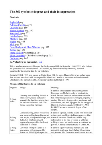
The cylinder valve has six key features:Valve ActuationConnectionValve Actuation Connection: A threaded connectionlocated on top of the cylinder valve serves as the attachment point for the electric (primary) or pneumatic(slave) valve actuator.DischargeOutletPressure Gauge Connection: A female connectionserves as the attachment point for the pressure gauge.It is fitted with an internal check valve to allow removalof the gauge while the cylinder is pressurized.Low-Pressure Supervisory Switch Connection: Afemale connection serves as the attachment point forthe low-pressure supervisory switch. An internal checkvalve allows for removal of the pressure switch whilethe cylinder is pressurized.Pressure GaugeConnectionPressure GaugeConnectionSafetyCapAnti-RecoilSafety DeviceRupture Disc: A frangible rupture disc fitted to thecylinder valve body functions as an emergency reliefdevice in the event of excessive pressure within thecylinder. Its rupture point is between 850 psi (58.6 bar)and 1000 psi (68.9 bar).Discharge Outlet: A 2 in (50 mm) grooved connection serves as the attachment point for discharge connection fittings.RuptureDiscPilot ActuationPortLow-PressureSupervisory SwitchConnectionPilot Actuation Port: A 1/4 in (8 mm) NPT connection(shipped with a removable plug) provides a means ofapplying actuation pressure to the slave cylinder(s).This can also be used for attachment of the dischargepressure switch in single cylinder arrangements. Theport is pressurized only during the 10 second discharge period.CYLINDER MOUNTING6.0”(152 mm)Wall Mount Cylinder Bracket Assembly(P/N 18535)Cylinder stability is ensured by the cylinder bracket assembly, consisting of one strap and rail with accompanying bolts, nuts, and washers. The rail is slotted for ease ofmounting with fasteners provided by the installer.H1Cylinder DimensionsD2H2250 lbH3D1DS1116Revised: 06-Feb-2015Page 3 of 10420 H319.850336.8935D116.040616.0406D217.945517.9455
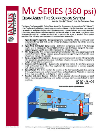
TRIM COMPONENTSTrim components are required to operate the clean agent cylinder(s).2” Grooved toNPT AdapterNipple(50 mm)(P/N 18474)2” GroovedCoupling(50 mm)(P/N 18555)2” GroovedElbow(50 mm)(P/N 18551)Manual ValveActuator(P/N 17001)Electric Valve Actuator(w/ Supervisory Limit Switch - P/N 20722)(w/o Supervisory Limit Switch- P/N 18481)2” GroovedCoupling(50 mm)(P/N 18555)Shipped withCylinder ValveLow-PressureSupervisory SwitchAssembly(P/N 18775)DischargeOutletLiquidLevelIndicatorAffixed toCylinderRupture DiscAffixed toCylinder ValveAnti-RecoilSafety DeviceShipped withCylinder ValvePressureGaugeAssembly(P/N 20529)8.21”(209 mm)(P/N 18474)Discharge Connection Fittings(P/N See Diagram)(P/N 18555)(P/N 18555)A 2 in (50 mm) grooved elbow, coupling, and NPT adapternipple connect to the grooved outlet adapter utilizing thecoupling factory installed to retain the anti-recoil safetydevice. Pipe and fittings beyond the 2 in (50 mm) adapternipple are to be supplied by the installer.(P/N 18551)36”(914 mm)LeadsLow-Pressure Supervisory Switch Assembly(P/N 18775)The low-pressure supervisory switch continuously monitors the pressure of the cylinder. The contact configuration is single pole, single throw (SPST) with contactsrated 1.5 Amps at 24 VDC. Should the cylinder pressuredrop to approximately 280 psi (19.3 bar), the switch contacts will close transmitting a signal to the system controlpanel.Pressure Gauge Assembly(P/N 20529)NFPA 2001 mandates a pressure gauge for each cylinder as a method of visually monitoring the internal pressure condition of the cylinder assembly.DS1116Revised: 06-Feb-2015Page 4 of 10
Electric Valve Actuatorw/ Supervisory Limit Switch¹ (P/N 20722)w/o Supervisory Limit Switch (P/N 18481)The electric valve actuator attaches to the primary cylinderat the valve actuation connection and is utilized to automatically open the cylinder valve upon receipt of a signal from thecontrol panel or other source. It operates between 17 and 30VDC and consumes 600 mA (.6 Amps) at 24 VDC nominalwith a maximum supervisory current of 30 mA (0.03 Amps).1/2” (15 mm)Conduit Connectorwith 36” (914 mm)LeadsKnurledSwivel NutEmergencyRelease ButtonThe electric valve actuator body is steel construction with abrass knurled swivel nut and a stainless steel actuation pinthat depresses the valve core when energized. In the modelwith supervisory limit switch, the switch contacts are normallyclosed when the actuator is not installed onto the cylindervalve and open when the actuator is fully installed onto thevalve actuation connection at the top of the cylinder valve.Manual Valve Actuator (P/N 17001)Ring PinAn optional manual valve actuator attaches to the top of theelectric valve actuator and provides a means to manuallyopen the cylinder valve. The manual valve actuator consistsof a brass body, stainless steel actuation pin, and steel safetyring pin.To discharge the primary cylinder manually, the ring pin is removed and the emergency release button is depressed forcing the pin in the electric valve actuator to depress the valvecore of the cylinder valve. All other connected cylinders willbe opened pneumatically.Knurled NutSLAVE ARRANGEMENT COMPONENTSUp to 16 cylinders (1 primary and 15 slave) may be installed in a single arrangement, with a maximumlength of 100 ft (30.48 m) of pilot actuation hose or tubing extending from the primary cylinder in eitherdirection. A typical arrangement is shown below.DischargePressure Switch(P/N 18773)Male NPTAdapter(P/N 18625)Variable SizeFlex Hose(P/N Variable)ManualValve Actuator(P/N 17001)Pilot ActuationMid Line Tee(P/N 18622)24” Flex Hose(610 mm)Discharge Manifold(P/N 18649) (Provided By Installer)Male NPTAdapter(P/N 18625)PneumaticValve Actuator(P/N 17019)2” (50 mm)ManifoldCheck Valve(P/N 18546)PilotActuationEnd LineTee(P/N 18611)Vent Check(P/N 10173)Electric Valve Actuatorw/ Supervisory Limit Switch(P/N 20722)w/o Supervisory Limit Switch(P/N 18481)Pilot ActuationCheck Valve(P/N veCylinderSlaveCylinderTypical Primary and Slave Cylinder ArrangementDS1116Revised: 06-Feb-2015Page 5 of 10¹ NFPA 2001, 2012 Edition, requires that the removal of an electric actuator from the agent storage container discharge valve that it controls shallresult in an audible and visual indication of system impairment at the system releasing control panel. This will become effective January 1, 2016.
1/4” (8 mm) FNPTPneumatic Valve Actuator (P/N 17019)On multiple cylinder systems the electric valve actuatorwill open the primary cylinder and then, in a rapidly occurring sequence, the pneumatic valve actuator(s) willopen all other cylinders using pressure from the primarycylinder.A pneumatic valve actuator attaches to the valve actuation connection of each slave cylinder. It receivespressure from the pilot actuation port of the primary cylinder through the pilot actuation check valve. It is brasswith a brass piston and pin.Knurled NutVent Check (P/N 10173)The vent check is a safety device with 1/4 in (8 mm)MNPT threads that is to be installed in the pilot actuationline downstream of the pilot actuation check valve. It isused to bleed off pressure that may accumulate in thepilot actuation hose or piping minimizing the chance ofinadvertent operation of the pneumatic actuators or discharge pressure switch.1/4” (8 mm)MNPTPilot Actuation Check Valve (P/N 18560)1/4” (8 mm)37 Male JIC1/4” (8 mm)MNPTA 1/4 in (8 mm) MNPT by 37 male JIC check valve isinstalled in the pilot actuation port of the primary cylindervalve with direction of flow OUT of the valve. When thevalve opens, pressure will be directed through the pilot actuation check valve to the pneumatic valve actuators on theslave cylinders. The purpose of the pilot actuation checkvalve is to ensure the pneumatic actuator(s) remain pressurized for the entire discharge period.Male NPT Adapter (P/N 18625)1/4” (8 mm)MNPT1/4” (8 mm)37 Male JICA 1/4 in (8 mm) 37 male JIC by MNPT adapter fits intothe pilot actuation end line tee of the final slave cylinderto facilitate the attachment of the pilot actuation line. Italso may be utilized to allow the attachment of flex hoseto the discharge pressure switch.Pilot Actuation Mid Line Tee (P/N 18622)1/4” (8 mm)37 Male JICDS1116Revised: 06-Feb-20151/4” (8 mm)MNPTA 1/4 in (8 mm) 37 male JIC by MNPT brass branch teeis utilized to attach the pilot actuation line to the pneumatic valve actuator.Page 6 of 10
Pilot Actuation End Line Tee (P/N 18611)A 1/4 in (8 mm) FNPT by MNPT brass branch tee mountsto the final pneumatic valve actuator to facilitate attachment of the vent check to the pilot actuation line.1/4” (8 mm)FNPT1/4” (8 mm)MNPTFlex Hose (P/N See Chart)Flex hoses are 3/16 in (7 mm) Teflon lined stainlesssteel wire braided hoses of varying lengths with 1/4 in(8 mm) 37 female JIC flare fittings. They are utilized tointerconnect cylinders when a slave arrangement is required. A 1/4 in (8 mm) 37 male JIC flare x male JICflare adapter (P/N 18777) is available to connect lengthsof flex hose together.LP/NHose Length (L)1864816 in (40
The Janus Fire Systems Mv Series Clean Agent Fire Suppression System utilizes 3M Novec 1230 Fire Protection Fluid as the extinguishing medium. Novec 1230 fluid is a clear, colorless and . low odor liquid perfectly suited to protect high value assets in areas that may be normally occupied, in locations where clean-up of other agents is problematic, when storage space for a fire suppres .