Transcription
CCNA200-301Official Cert Guide,Volume 1WENDELL ODOM, CCIE No. 1624 EmeritusCisco Press221 River St. (3D11C)Hoboken, NJ 070309780135792735 book.indb i7/25/19 2:45 PM
iiCCNA 200-301 Official Cert Guide, Volume 1CCNA 200-301 Official Cert Guide,Volume 1Wendell OdomCopyright 2020 Pearson Education, Inc.Published by:Cisco PressAll rights reserved. No part of this book may be reproduced or transmitted in any form or by any means,electronic or mechanical, including photocopying, recording, or by any information storage and retrievalsystem, without written permission from the publisher, except for the inclusion of brief quotations in areview.ScoutAutomatedPrintCodeLibrary of Congress Control Number: 2019908180ISBN-13: 978-0-13-579273-5ISBN-10: 0-13-579273-8Warning and DisclaimerThis book is designed to provide information about the Cisco CCNA 200-301 exam. Every effort hasbeen made to make this book as complete and as accurate as possible, but no warranty or fitness isimplied.The information is provided on an “as is” basis. The authors, Cisco Press, and Cisco Systems, Inc. shallhave neither liability nor responsibility to any person or entity with respect to any loss or damagesarising from the information contained in this book or from the use of the discs or programs that mayaccompany it.The opinions expressed in this book belong to the author and are not necessarily those of Cisco Systems,Inc.Trademark AcknowledgmentsAll terms mentioned in this book that are known to be trademarks or service marks have been appropriately capitalized. Cisco Press or Cisco Systems, Inc., cannot attest to the accuracy of this information.Use of a term in this book should not be regarded as affecting the validity of any trademark or servicemark.9780135792735 book.indb ii7/25/19 2:45 PM
iiiSpecial SalesFor information about buying this title in bulk quantities, or for special sales opportunities (which mayinclude electronic versions; custom cover designs; and content particular to your business, traininggoals, marketing focus, or branding interests), please contact our corporate sales department atcorpsales@pearsoned.com or (800) 382-3419.For government sales inquiries, please contact governmentsales@pearsoned.com.For questions about sales outside the U.S., please contact intlcs@pearson.com.Feedback InformationAt Cisco Press, our goal is to create in-depth technical books of the highest quality and value. Each bookis crafted with care and precision, undergoing rigorous development that involves the unique expertiseof members from the professional technical community.Readers’ feedback is a natural continuation of this process. If you have any comments regarding how wecould improve the quality of this book, or otherwise alter it to better suit your needs, you can contact usthrough email at feedback@ciscopress.com. Please make sure to include the book title and ISBN in yourmessage.We greatly appreciate your assistance.Editor-in-Chief: Mark TaubTechnical Editor: Elan BeerBusiness Operation Manager, Cisco Press: Ronald FliggeEditorial Assistant: Cindy TeetersDirector ITP Product Management: Brett BartowCover Designer: Chuti PrasertsithManaging Editor: Sandra SchroederComposition: Tricia BronkellaDevelopment Editor: Christopher ClevelandIndexer: Ken JohnsonSenior Project Editor: Tonya SimpsonProofreader: Debbie WilliamsCopy Editor: Chuck Hutchinson9780135792735 book.indb iii7/25/19 2:45 PM
ivCCNA 200-301 Official Cert Guide, Volume 1About the AuthorWendell Odom, CCIE No. 1624 Emeritus, has been in the networking industry since1981. He has worked as a network engineer, consultant, systems engineer, instructor, andcourse developer; he currently works writing and creating certification study tools. Thisbook is his 28th edition of some product for Pearson, and he is the author of all editionsof the CCNA Cert Guides about Routing and Switching from Cisco Press. He has writtenbooks about topics from networking basics, certification guides throughout the yearsfor CCENT, CCNA R&S, CCNA DC, CCNP ROUTE, CCNP QoS, and CCIE R&S. Hemaintains study tools, links to his blogs, and other resources at www.certskills.com.9780135792735 book.indb iv7/25/19 2:45 PM
CHAPTER 17IP Routing in the LANThis chapter covers the following exam topics:1.0 Network Fundamentals1.6 Configure and verify IPv4 addressing and subnetting2.0 Network Access2.4 Configure and verify (Layer 2/Layer 3) EtherChannel (LACP)The preceding two chapters showed how to configure an IP address and mask on a routerinterface, making the router ready to route packets to/from the subnet implied by thataddress/mask combination. While true and useful, all the examples so far ignored the LANswitches and the possibility of VLANs. In fact, the examples so far show the simplest possible cases: the attached switches as Layer 2 switches, using only one VLAN, with the routerconfigured with one ip address command on its physical interface. This chapter takes adetailed look at how to configure routers so that they route packets to/from the subnets thatexist on each and every VLAN.Because Layer 2 switches do not forward Layer 2 frames between VLANs, a network mustuse routers to route IP packets between subnets to allow those devices in different VLANs/subnets to communicate. To review, Ethernet defines the concept of a VLAN, while IPdefines the concept of an IP subnet, so a VLAN is not equivalent to a subnet. However, theset of devices in one VLAN are typically also in one subnet. By the same reasoning, devicesin two different VLANs are normally in two different subnets. For two devices in differentVLANs to communicate with each other, routers must connect to the subnets that exist oneach VLAN, and then the routers forward IP packets between the devices in those subnets.This chapter discusses the configuration and verification steps related to three methods ofrouting between VLANs with three major sections: VLAN Routing with Router 802.1Q Trunks: The first section discusses how to configure a router to use VLAN trunking as connected to a Layer 2 switch. The router does therouting, with the switch creating the VLANs. The link between the router and switch usetrunking so that the router has an interface connected to each VLAN/subnet. This featureis known as routing over a VLAN trunk and also known as router-on-a-stick (ROAS). VLAN Routing with Layer 3 Switch SVIs: The second section discusses using a LANswitch that supports both Layer 2 switching and Layer 3 routing (called a Layer 3 switchor multilayer switch). To route, the Layer 3 switch configuration uses interfaces calledswitched virtual interfaces (SVI), which are also called VLAN interfaces. VLAN Routing with Layer 3 Switch Routed Ports: The third major section of the chapter discusses an alternative to SVIs called routed ports, in which the physical switch portsare made to act like interfaces on a router. This third section also introduces the conceptof an EtherChannel as used as a routed port in a feature called Layer 3 EtherChannel.9780135792735 book.indb 3927/25/19 2:45 PM
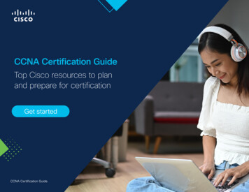
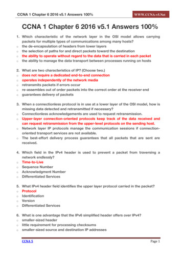
Chapter 17: IP Routing in the LAN395Foundation TopicsVLAN Routing with Router 802.1Q TrunksAlmost all enterprise networks use VLANs. To route IP packets in and out of those VLANs,some devices (either routers or Layer 3 switches) need to have an IP address in each subnetand have a connected route to each of those subnets. Then the IP addresses on those routersor Layer 3 switches can serve as the default gateways in those subnets.This chapter breaks down the LAN routing options into four categories: Use a router, with one router LAN interface and cable connected to the switch for eachand every VLAN (typically not used) Use a router, with a VLAN trunk connecting to a LAN switch (known as router-on-astick, or ROAS) Use a Layer 3 switch with switched virtual interfaces (SVI) Use a Layer 3 switch with routed interfaces (which may or may not be Layer 3EtherChannels)17Of the items in the list, the first option works, but to be practical, it requires far too manyinterfaces. It is mentioned here only to make the list complete.As for the other three options, this chapter discusses each in turn as the main focus of oneof the three major sections in this chapter. Each feature is used in real networks today, withthe choice to use one or the other driven by the design and needs for a particular part of thenetwork. Figure 17-1 shows cases in which these options could be used.VLAN Trunking2 VLANsLayer 3SwitchesB1SW112 VLANs2 VLANsDACBCoreB22 VLANsB3Figure 17-1SW2SW3Layer 3 Switching at the Central SiteFigure 17-1 shows two switches, labeled A and B, which could act as Layer 3 switches—bothwith SVIs and routed interfaces. The figure shows a central site campus LAN on the left,with 12 VLANs. Switches A and B act as Layer 3 switches, combining the functions of arouter and a switch, routing between all 12 subnets/VLANs, as well as routing to/from theCore router. Those Layer 3 switches could use SVIs, routed interfaces, or both.Figure 17-1 also shows a classic case for using a router with a VLAN trunk. Sites like theremote sites on the right side of the figure may have a WAN-connected router and a LAN9780135792735 book.indb 3957/25/19 2:45 PM
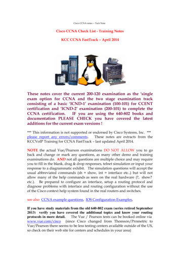
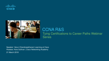
396CCNA 200-301 Official Cert Guide, Volume 1switch. These sites might use ROAS to take advantage of the router’s ability to route over an802.1Q trunk.Note that Figure 17-1 just shows an example. The engineer could use Layer 3 switching ateach site or routers with VLAN trunking at each site.Configuring ROASThis next topic discusses how routers route packets to subnets associated with VLANs connected to a router 802.1Q trunk. That long description can be a bit of a chore to repeat eachtime someone wants to discuss this feature, so over time, the networking world has insteadsettled on a shorter and more interesting name for this feature: router-on-a-stick (ROAS).ROAS uses router VLAN trunking configuration to give the router a logical router interface connected to each VLAN. Because the router then has an interface connected to eachVLAN, the router can also be configured with an IP address in the subnet that exists on eachVLAN.Routers use subinterfaces as the means to have an interface connected to a VLAN. Therouter needs to have an IP address/mask associated with each VLAN on the trunk. However,the router has only one physical interface for the link connected to the trunk. Cisco solvesthis problem by creating multiple virtual router interfaces, one associated with each VLANon that trunk (at least for each VLAN that you want the trunk to support). Cisco calls thesevirtual interfaces subinterfaces. The configuration can then include an ip address commandfor each subinterface.Figure 17-2 shows the concept with Router B1, one of the branch routers from Figure 17-1.Because this router needs to route between only two VLANs, the figure also shows two subinterfaces, named G0/0.10 and G0/0.20, which create a new place in the configuration wherethe per-VLAN configuration settings can be made. The router treats frames tagged withVLAN 10 as if they came in or out of G0/0.10 and frames tagged with VLAN 20 as if theycame in or out G0/0.20.10.1.10.1/24VLAN 10Interface G0/0.1020102010B120SW1Interface G0/0.2010.1.20.1/24Figure 17-2VLAN 20Subinterfaces on Router B1In addition, note that most Cisco routers do not attempt to negotiate trunking, so both therouter and switch need to manually configure trunking. This chapter discusses the routerside of that trunking configuration; the matching switch interface would need to be configured with the switchport mode trunk command.Answers to the “Do I Know This Already?” quiz:1 A, F 2 B, C 3 C 4 C, D 5 A, C 6 B, C9780135792735 book.indb 3967/25/19 2:45 PM
Chapter 17: IP Routing in the LAN397Example 17-1 shows a full example of the 802.1Q trunking configuration required on RouterB1 in Figure 17-2. More generally, these steps detail how to configure 802.1Q trunking on arouter:ConfigChecklistStep 1.Use the interface type number.subint command in global configuration modeto create a unique subinterface for each VLAN that needs to be routed.Step 2.Use the encapsulation dot1q vlan id command in subinterface configurationmode to enable 802.1Q and associate one specific VLAN with the subinterface.Step 3.Use the ip address address mask command in subinterface configuration modeto configure IP settings (address and mask).Example 17-1 Router Configuration for the 802.1Q Encapsulation Shown in Figure 17-217B1# show running-config! Only pertinent lines showninterface gigabitethernet 0/0! No IP address up here! No encapsulation up here!!interface gigabitethernet 0/0.10encapsulation dot1q 10ip address 10.1.10.1 255.255.255.0!interface gigabitethernet 0/0.20encapsulation dot1q 20ip address 10.1.20.1 255.255.255.0First, look at the subinterface numbers. The subinterface number begins with the period, like.10 and .20 in this case. These numbers can be any number from 1 up through a very largenumber (over 4 billion). The number just needs to be unique among all subinterfaces associated with this one physical interface. In fact, the subinterface number does not even haveto match the associated VLAN ID. (The encapsulation command, and not the subinterfacenumber, defines the VLAN ID associated with the subinterface.)NOTE Although not required, most sites do choose to make the subinterface numbermatch the VLAN ID, as shown in Example 17-1, just to avoid confusion.Each subinterface configuration lists two subcommands. One command (encapsulation)enables trunking and defines the VLAN whose frames are considered to be coming in andout of the subinterface. The ip address command works the same way it does on any otherinterface. Note that if the physical Ethernet interface reaches an up/up state, the subinterfaceshould as well, which would then let the router add the connected routes shown at the bottom of the example.Now that the router has a working interface, with IPv4 addresses configured, the router canroute IPv4 packets on these subinterfaces. That is, the router treats these subinterfaces like9780135792735 book.indb 3977/25/19 2:45 PM
398CCNA 200-301 Official Cert Guide, Volume 1any physical interface in terms of adding connected routes, matching those routes, and forwarding packets to/from those connected subnets.The configuration and use of the native VLAN on the trunk require a little extra thought. Thenative VLAN can be configured on a subinterface, or on the physical interface, or ignored as inExample 17-1. Each 802.1Q trunk has one native VLAN, and if the router needs to route packets for a subnet that exists in the native VLAN, then the router needs some configuration tosupport that subnet. The two options to define a router interface for the native VLAN are Configure the ip address command on the physical interface, but without anencapsulation command; the router considers this physical interface to be using thenative VLAN. Configure the ip address command on a subinterface and use the encapsulation dot1qvlan-id native subcommand to tell the router both the VLAN ID and the fact that it is thenative VLAN.Example 17-2 shows both native VLAN configuration options with a small change to thesame configuration in Example 17-1. In this case, VLAN 10 becomes the native VLAN. Thetop part of the example shows the option to configure the router physical interface to usenative VLAN 10. The second half of the example shows how to configure that same nativeVLAN on a subinterface. In both cases, the switch configuration also needs to be changedto make VLAN 10 the native VLAN.Example 17-2Router Configuration Using Native VLAN 10 on Router B1! First option: put the native VLAN IP address on the physical interfaceinterface gigabitethernet 0/0ip address 10.1.10.1 255.255.255.0!interface gigabitethernet 0/0.20encapsulation dot1q 20ip address 10.1.20.1 255.255.255.0! Second option: like Example 17-1, but add the native keywordinterface gigabitethernet 0/0.10encapsulation dot1q 10 nativeip address 10.1.10.1 255.255.255.0!interface gigabitethernet 0/0.20encapsulation dot1q 20ip address 10.1.20.1 255.255.255.0Verifying ROASBeyond using the show running-config command, ROAS configuration on a router can bebest verified with two commands: show ip route [connected] and show vlans. As with anyrouter interface, as long as the interface is in an up/up state and has an IPv4 address configured, IOS will put a connected (and local) route in the IPv4 routing table. So, a first andobvious check would be to see if all the expected connected routes exist. Example 17-3 liststhe connected routes per the configuration shown in Example 17-1.9780135792735 book.indb 3987/25/19 2:45 PM
Chapter 17: IP Routing in the LANExample 17-3399Connected Routes Based on Example 17-1 ConfigurationB1# show ip route connectedCodes: L - local, C - connected, S - static, R - RIP, M - mobile, B - BGP! Legend omitted for brevity10.0.0.0/8 is variably subnetted, 4 subnets, 2 masksC10.1.10.0/24 is directly connected, GigabitEthernet0/0.10L10.1.10.1/32 is directly connected, GigabitEthernet0/0.10C10.1.20.0/24 is directly connected, GigabitEthernet0/0.20L10.1.20.1/32 is directly connected, GigabitEthernet0/0.20As for interface and subinterface state, note that the ROAS subinterface state does dependto some degree on the physical interface state. In particular, the subinterface state cannotbe better than the state of the matching physical interface. For instance, on Router B1 in theexamples so far, physical interface G0/0 is in an up/up state, and the subinterfaces are in anup/up state. But if you unplugged the cable from that port, the physical port would fail to adown/down state, and the subinterfaces would also fail to a down/down state. Example 17-4shows another example, with the physical interface being shut down, with the subinterfacesthen automatically changed to an administratively down state as a result.Example 17-417Subinterface State Tied to Physical Interface StateB1# configure terminalEnter configuration commands, one per line. End with CNTL/Z.B1(config)# interface g0/0B1(config-if)# shutdownB1(config-if)# ZB1# show ip interface brief include 0/0GigabitEthernet0/0unassignedYES manual administratively down downGigabitEthernet0/0.1010.1.10.1YES manual administratively down downGigabitEthernet0/0.2010.1.20.1YES manual administratively down downAdditionally, the subinterface state can also be enabled and disabled independently from thephysical interface, using the no shutdown and shutdown commands in subinterface configuration mode.Another useful ROAS verification command, show vlans, spells out which router trunk interfaces use which VLANs, which VLAN is the native VLAN, plus some packet statistics. Thefact that the packet counters are increasing can be useful when verifying whether traffic ishappening or not. Example 17-5 shows a sample, based on the Router B1 configuration inExample 17-2 (bottom half), in which native VLAN 10 is configured on subinterface G0/0.10.Note that the output identifies VLAN 1 associated with the physical interface, VLAN 10as the native VLAN associated with G0/0.10, and VLAN 20 associated with G0/0.20. It alsolists the IP addresses assigned to each interface/subinterface.9780135792735 book.indb 3997/25/19 2:45 PM
400CCNA 200-301 Official Cert Guide, Volume 1Example 17-5ConfigurationSample show vlans Command to Match Sample Router TrunkingR1# show vlansVirtual LAN ID: 1 (IEEE 802.1Q Encapsulation)vLAN Trunk Interface: GigabitEthernet0/0Protocols Configured:Address:Received:Other0Transmitted:8369 packets, 20914 bytes input147 packets, 11841 bytes outputVirtual LAN ID:10 (IEEE 802.1Q Encapsulation)vLAN Trunk Interface:GigabitEthernet0/0.10This is configured as native Vlan for the following interface(s) :GigabitEthernet0/0Native-vlan Tx-type: UntaggedProtocols itted:23013 packets, 722 bytes input4 packets, 264 bytes outputVirtual LAN ID:20 (IEEE 802.1Q Encapsulation)vLAN Trunk Interface:Protocols 1OtherReceived:Transmitted:0134010 packets, 0 bytes input135 packets, 10498 bytes outputTroubleshooting ROASThe biggest challenge when troubleshooting ROAS has to do with the fact that if you misconfigure only the router or misconfigure only the switch, the other device on the trunk hasno way to know that the other side is misconfigured. That is, if you check the show ip routeand show vlans commands on a router, and the output looks like it matches the intendedconfiguration, and the connected routes for the correct subinterfaces show up, routing maystill fail because of problems on the attached switch. So, troubleshooting ROAS often beginswith checking the configuration on both the router and switch because there is no statusoutput on either device that tells you where the problem might be.9780135792735 book.indb 4007/25/19 2:45 PM
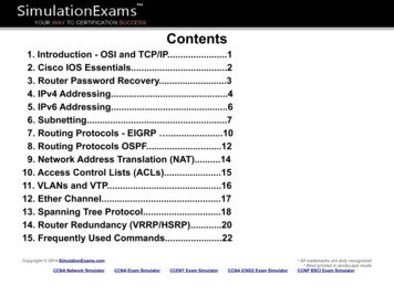
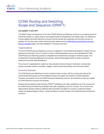
Chapter 17: IP Routing in the LAN401First, to check ROAS on the router, you need to start with the intended configuration andask questions about the configuration:1.Is each non-native VLAN configured on the router with an encapsulation dot1qvlan-id command on a subinterface?2.Do those same VLANs exist on the trunk on the neighboring switch (show interfacestrunk), and are they in the allowed list, not VTP pruned, and not STP blocked?3.Does each router ROAS subinterface have an IP address/mask configured per theplanned configuration?4.If using the native VLAN, is it configured correctly on the router either on a subinterface (with an encapsulation dot1q vlan-id native command) or implied on the physicalinterface?5.Is the same native VLAN configured on the neighboring switch’s trunk in comparisonto the native VLAN configured on the router?6.Are the router physical or ROAS subinterfaces configured with a shutdown command?17For some of these steps, you need to be ready to investigate possible VLAN trunking issueson the LAN switch. The reason is that on many Cisco routers, router interfaces do not negotiate trunking. As a result, ROAS relies on static trunk configuration on both the router andswitch. If the switch has any problems with VLANs or the VLAN trunking configuration onits side of the trunk, the router has no way to realize that the problem exists.For example, imagine you configured ROAS on a router just like in Example 17-1 or Example17-2. However, the switch on the other end of the link had no matching configuration. Forinstance, maybe the switch did not even define VLANs 10 and 20. Maybe the switch did notconfigure trunking on the port connected to the router. Even with blatant misconfigurationor missing configuration on the switch, the router still shows up/up ROAS interfaces andsubinterfaces, IP routes in the output of show ip route, and meaningful configuration information in the output of the show vlans command.VLAN Routing with Layer 3 Switch SVIsUsing a router with ROAS to route packets makes sense in some cases, particularly at smallremote sites. In sites with a larger LAN, network designers choose to use Layer 3 switchesfor most inter-VLAN routing.A Layer 3 switch (also called a multilayer switch) is one device, but it executes logic at twolayers: Layer 2 LAN switching and Layer 3 IP routing. The Layer 2 switch function forwardsframes inside each VLAN, but it will not forward frames between VLANs. The Layer 3 forwarding (routing) logic forwards IP packets between VLANs.Layer 3 switches typically support two configuration options to enable IPv4 routing inside theswitch, specifically to enable IPv4 on switch interfaces. This section explains one option, anoption that uses switched virtual interfaces (SVI). The final major section of the chapter dealswith the other option for configuring IPv4 addresses on Layer 3 switches: routed interfaces.Configuring Routing Using Switch SVIsThe configuration of a Layer 3 switch mostly looks like the Layer 2 switching configuration shown back in Parts II and III of this book, with a small bit of configuration added for9780135792735 book.indb 4017/25/19 2:45 PM
402CCNA 200-301 Official Cert Guide, Volume 1the Layer 3 functions. The Layer 3 switching function needs a virtual interface connected toeach VLAN internal to the switch. These VLAN interfaces act like router interfaces, withan IP address and mask. The Layer 3 switch has an IP routing table, with connected routesoff each of these VLAN interfaces. (These interfaces are also referred to as switched virtualinterfaces [SVI].)To show the concept of Layer 3 switching with SVIs, the following example uses the samebranch office with two VLANs shown in the earlier examples, but now the design will useLayer 3 switching in the LAN switch. Figure 17-3 shows the design changes and configuration concept for the Layer 3 switch function with a router icon inside the switch, to emphasize that the switch routes the packets.The Middle Box Represents the Layer 3 Switch,with Internal Logic VisibleVLAN 30B1G0/010.1.30.2interface vlan 30G0/1 10.1.30.1/24VLAN 10interface vlan 1010.1.10.1/24F0/1interface vlan 2010.1.20.1/24F0/3F0/2F0/4VLAN 20Figure 17-3Routing on VLAN Interfaces in a Layer 3 SwitchNote that the figure represents the internals of the Layer 3 switch within the box in themiddle of the figure. The branch still has two user VLANs (10 and 20), so the Layer 3 switchneeds one VLAN interface for each VLAN. The figure shows a router icon inside the graybox to represent the Layer 3 switching function, with two VLAN interfaces on the right sideof that icon. In addition, the traffic still needs to get to router B1 (a physical router) to accessthe WAN, so the switch uses a third VLAN (VLAN 30 in this case) for the link to RouterB1. The physical link between the Layer 3 switch and router B1 would not be a trunk, butinstead be an access link.The following steps show how to configure Layer 3 switching using SVIs. Note that on someswitches, like the 2960 and 2960-XR switches used for the examples in this book, the abilityto route IPv4 packets must be enabled first, with a reload of the switch required to enablethe feature. The steps that occur after the reload would apply to all models of Cisco switchesthat are capable of doing Layer 3 switching.ConfigChecklistStep 1.Enable IP routing on the switch, as needed:A. Use the sdm prefer lanbase-routing command (or similar) in global configuration mode to change the switch forwarding ASIC settings to make spacefor IPv4 routes at the next reload of the switch.B. Use the reload EXEC command in enable mode to reload (reboot) theswitch to pick up the new sdm prefer command setting.C. Once reloaded, use the ip routing command in global configuration modeto enable the IPv4 routing function in IOS software and to enable key commands like show ip route.9780135792735 book.indb 4027/25/19 2:45 PM
Chapter 17: IP Routing in the LANStep 2.403Configure each SVI interface, one per VLAN for which routing should be doneby this Layer 3 switch:A. Use the interface vlan vlan id command in global configuration mode tocreate a VLAN interface and to give the switch’s routing logic a Layer 3interface connected into the VLAN of the same number.B. Use the ip address address mask command in VLAN interface configuration mode to configure an IP address and mask on the VLAN interface,enabling IPv4 routing on that VLAN interface.C. (As needed) Use the no shutdown command in interface configurationmode to enable the VLAN interface (if it is currently in a shutdown state).Example 17-6 shows the configuration to match Figure 17-3. In this case, switch SW1 hasalready used the sdm prefer global command to change to a setting that supports IPv4 routing, and the switch has been reloaded. The example shows the related configuration on allthree VLAN interfaces.Example 17-617VLAN Interface Configuration for Layer 3 Switchingip routing!interface vlan 10ip address 10.1.10.1 255.255.255.0!interface vlan 20ip address 10.1.20.1 255.255.255.0!interface vlan 30ip address 10.1.30.1 255.255.255.0Verifying Routing with SVIsWith the VLAN configuration shown in the previous section, the switch is ready to routepackets between the VLANs as shown in Figure 17-3. To support the routing of packets, theswitch adds connected IP routes as shown in Example 17-7; note that each route is listed asbeing connected to a different VLAN interface.Example 17-7Connected Routes on a Layer 3 SwitchSW1# show ip route! legend omitted for brevity10.0.0.0/8 is variably subnetted, 6 subnets, 2 masksC10.1.10.0/24 is directly connected, Vlan10L10.1.10.1/32 is directly connected, Vlan10C10.1.20.0/24 is directly connected, Vlan20L10.1.20.1/32 is directly connected, Vlan20C10.1.30.0/24 is directly connected, Vlan30L10.1.30.1/32 is directly connected, Vlan309780135792735 book.indb 4037/25/19 2:45 PM
404CCNA 200-301 Official Cert Guide, Volume 1The switch would also need additional routes to the rest of the network (not shown in thefigures in this chapter). The Layer 3 switch could use static routes or a routing protocol,depending on the capabilities of the switch. For instance, if you then enabled OSPF on theLayer 3 switch, the configuration and verification would work the same as it does on a router, as discussed in Chapter 20, “Implementing OSPF.” The routes that IOS adds to the Layer3 switch’s IP routing table would list the VLAN interfaces as outgoing interfaces.NOTE Some models of Cisco enterprise switches, based on model, IOS version, and IOSfeature set, support different capabilities for IP routing and routing protocols, so for real networks, check the capabilities of the switch model by browsing at Cisco.com. In particular,check the Cisco Feature Navigator (CFN) tool at http://www.cisco.com/go/cfn.Troubleshooting Routing with SVIsThere are two big topics to investigate when troubleshooting routing over LANs with SVIs.First, you have to make sure the switch has
At Cisco Press, our goal is to create in-depth technical books of the highest quality and value. Each book is crafted with care and precision, undergoing rigorous development that involves the unique expertise of members from the professional technical community. Rea