Transcription
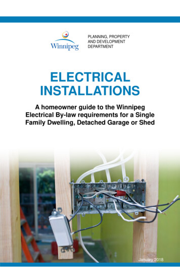
PLANNING, PROPERTYAND DEVELOPMENTDEPARTMENTELECTRICALINSTALLATIONSA homeowner guide to the WinnipegElectrical By-law requirements for a SingleFamily Dwelling, Detached Garage or ShedJanuary 2018
contentsGeneral Information.3Circuits & Receptacles.5Recreation Rooms & Additions.9Smoke & Carbon Monoxide Alarms. 11Garages & Sheds. 12Electrical Service Changes. 16Specific Wiring Methods. 20Note:This booklet has been written to:1. Provide an outline of some of the more commonelectrical regulations applicable to electricalinstallations done by the home owner; and2. Provide information on the extent to which theelectrical work must be completed prior to requestingan inspection.The applicable sections of this booklet should be reviewedprior to commencing the project. Please note that thisbooklet is not intended to cover all of the electricalregulations for wiring. For complete electrical requirementsplease refer to the City of Winnipeg Electrical By-law.2Every effort has been made to ensure the accuracy ofinformation contained in this publication. However, in the eventof a discrepancy between this publication and the governingCity of Winnipeg By-law, the By-law will take precedence.
Electrical Permit ApplicantAn electrical permit may be issued to:a) a person who holds an Electrical Contractor’s License fromthe City of Winnipeg authorizing that person to carry outbusiness or trade in the City of Winnipeg; ORb) the owner of a detached single family dwelling who is alsothe occupant. The owner must actually do the work. Thepermit would be issued to the owner provided the Managerof Development and Inspections is confident the work will beperformed competently.Information Required for an Electrical Permit ApplicationTo obtain an electrical permit, the applicant must present a wiringdiagram for the proposed installation indicating the location ofreceptacles, lights, switches and all other electrical equipmentto be installed. The wiring plan submitted should be comparableto the typical wiring plans shown on pages 8 and 9. It is notnecessary to show any existing wiring that will not be altered.general informationWork Requiring an Electrical PermitAn electrical permit must be obtained from the City of WinnipegPlanning, Property and Development Department at 31 - 30 FortStreet, prior to the construction, alteration, repair, or extension ofany electrical installation.Permit ExpirationThe permit will expire if active work is not commenced within six(6) months from the date of issuance and completed within three(3) years from the date of issuance. In addition, the Manager ofDevelopment & Inspections may cancel any electrical permit if, inhis opinion, the privileges granted by that permit are being misused.Responsibility for Work Performed Under this PermitThe permit applicant assumes full responsibility for electricalwork indicated on the permit and must ensure that the workconforms to all requirements of the Electrical By-Law.Number of Inspections Required for Lower LevelDevelopment, Additions, and other Similar ApplicationsThe wiring in areas such as lower level development, additions,and other similar installations, is normally allotted two inspections.The first inspection is made prior to covering any of the electricalinstallation with insulation or wall board.3
general informationThe second inspection is made on completion of the work.Where additional inspections are found to be necessary anadditional inspection fee may be levied.First Inspection - rough-inBefore calling for the first inspection, the following work is to becompleted:1. All the wiring for lights, switches, and receptacles are to beinstalled in the walls, secured to the structural membersand terminated in the outlet boxes.2. All connections, joints, and bonding in the outlet boxesmust be completed, leaving unconnected only theconductors required for the connection of the light,receptacle or switch (see FIGURE 12 Typical Outlet BoxInstallation” on page 22).3. At least one receptacle, light, and switch is to be connectedto the wiring.4. The wiring and connection of the 3-way switches requiredfor the stairway lighting are to be completed.5. If recessed lighting fixtures are to be installed, at least onefixture is to be completed.6. The conductors are to be run into the electrical panelwith the bonding (bare) conductor terminated under thebond screw and the neutral wire connected to the neutralterminal. The wires must not be connected to the circuitbreaker until the wiring is complete.7. Once the rough-in is complete you need to schedule aninspection by emailing ppd-housing@winnipeg.ca or bycalling 204-986-5300.Final InspectionFor the final inspection, the electrical installation is to be fullycompleted in that all the light fixtures, receptacles, smoke/COalarms, switches and cover plates are to be installed andconnected to the normal power supply. The electricalcircuits in the panel must be clearly identified on the paneldirectory. You can arrange your final inspection by emailingppd-housing@winnipeg.ca or by calling 204-986-5300.4
1. A maximum of 12 outlets (lights and receptacles) may beconnected to each 15 Amp branch circuit.2. The maximum number of conductors permitted in an outletbox is shown in TABLE 1.TABLE 1 - Maximum Number of Conductors Allowedin Outlet BoxesBox Dimensions(inches)DeviceOctagon BoxesMaximum number ofconductors permitted#14#12#103 X 2 X 1 1/25433X2X26543 X 2 X 2 1/46543 X 2 X 2 1/28753X2X310864 X 1 1/210864 X 2 1/814129circuits & receptaclesElectrical Installation Requirements for Finished RoomsSee FIGURES 1 and 2 on pages 9 and 10 for typical electricalplans for main floors and lower level development.1) The bare bonding conductors in cables are not counted.2) 2 conductors must be deducted from the number shown inthe table for each switch or receptacle to be installed.3) One conductor must be deducted for each pair of wireconnectors in the4) A “device” box typically contains a receptacle or switch.EXAMPLE: A 3”x 2”x 2” box allows 6 #14 conductors. If areceptacle is to be installed, 2 conductors must be deductedfrom the number shown in Table 1 (6 – 2 4). Note that nowonly 4 conductors are allowed in the 3”x 2”x 2” box with areceptacle. Therefore, one 2 conductor cable may enter theoutlet box and one 2 conductor cable may leave the outlet box.Receptacles (general)1. Receptacles must be located so that no point on the wall ismore than 1.8 m (6’) horizontally from a receptacle (measuredalong the floor line). Walls longer than 900 mm (36”) requirereceptacles spaced not more than 3.6 m (12’) apart.5
circuits & receptaclesDo not count wall space occupied by:a) Doorways and the area occupied by doors when fullyopenedb) Windows that extend to the floor, andc) Other permanent installations that would limit the use ofthe wall space (fireplaces, clothes closets, etc.). Thesereceptacles are normally installed 300-400 mm (12”-16”)above finished floor.2. Item 1 is not applicable in washrooms, bathrooms,hallways, laundry rooms or closets but must be installed inbasement walls that are finished with drywall, paneling, etc.to within 450 mm (18”) of the basement floor.3. At least one receptacle, supplied by a separate branchcircuit, must be provided in each utility room and also ineach unfinished basement area.4. Where a complete piped system for a cord-connectedcentral vacuum system is installed, a receptacle suppliedby a separate branch circuit must be provided.5. One single receptacle, labelled “SUMP PUMP ONLY”,supplied by a separate branch circuit, must be provided fora sump pump6. All 15 and 20 amp receptacles must be the tamperresistant (TR) type unless they are dedicated for stationaryappliances and rendered inaccessible or located more than2 m (6’-6”) above the floor.7. All 15 and 20 Amp receptacle circuits must be protectedby a combination arc fault circuit interrupter (AFCI) withthe exception of branch circuits supplying receptacles inbathrooms & washrooms, a refrigerator, or kitchen countersand branch circuits provided solely for:a) Single receptacles for sump pumps and receptacles indetached garages or other out-buildingsb) Outdoor receptacles*6Lighting (general)1. A switch controlling a lighting fixture or a receptacle mustbe installed for every room. If only one half of a duplexreceptacle is switched, it will also qualify as one of thereceptacles required in Receptacles Item 1.2. The maximum rating of circuit breaker permitted for anycircuit supplying light fixtures is 15 Amps.
Bathrooms & Washrooms1. A receptacle must be installed within 1 m (39”) of eachwash basin located in a bathroom or washroom.2. Receptacles and switches installed in bathrooms must belocated at least 1 m (39”) from a bathtub or shower stall.3. Receptacles installed within 1.5 m (5’) of a wash basin,bathtub or shower stall must be protected by a Class A typeground fault circuit interrupter (GFCI).4. If there is no central exhaust or HRV, bathrooms &washrooms must have an electrically wired mechanicalexhaust fan venting directly to the outdoors.5. Electrical equipment associated with “jetted” (ie:hydromassage) bathtubs must be protected with a GFCI.Kitchens1. Kitchen counter receptacles must be located on the wallbehind the counter work surface so that no point alongthe wall is more than 900 mm (3’) from a receptacle. Thisgenerally requires that receptacles be spaced 1.8 m (6’) apart.2. Sinks, built-in equipment and isolated work surfaces lessthan 300 mm (12”) long at the wall, need not be includedwhen calculating the spacing of counter receptacles.3. At least one receptacle must be provided at eachpermanently fixed island counter and on each peninsularcounter space that is 300 mm x 600 mm (12”- 24”) orlarger. An island counter is considered to be permanentlyfixed unless it is mounted on wheels.4. Kitchen counter receptacles must be either 15 Amp splittype as illustrated in Figure 20 on page 26, or 20 AmpT-slot.5. A receptacle, supplied by a separate branch circuit, mustbe installed for a refrigerator. An outlet for a recessed clockmay also be connected to this circuit.6. Receptacles installed within 1.5 m (5’) of sinks must beprotected by a GFCI.circuits & receptacles3. Every stairway must be lighted. A light fixture whichilluminates a stair having 4 or more risers must be controlledby 3-way switches at the top and bottom of the stairs. If thelower level is not finished, the light fixture is permitted to becontrolled by a single switch located at the head of the stairsand provisions for 3-way switching must be installed.7
circuits & receptacles8Outdoor/Garage Receptacles1. All receptacles located outdoors and within 2.5 m (8’) ofground or grade level must be protected by a GFCI.2. At least one receptacle, supplied by a separate branchcircuit, must be provided outdoors for the use of electricappliances.3. At least one receptacle, supplied by a separate branchcircuit, must be provided for each driveway.4. At least one light fixture must be provided in a garage.5. At least one receptacle must be provided for each carspace in a garage or carport. At least one separate branchcircuit must be provided for the receptacle(s) except thatthe garage/ carport lighting and garage door opener(s) mayalso be connected to this circuit.
Lighting Outlet Single Pole SwitchFIGURE 1 - Wiring Plan For Typical Main Floorrecreation rooms & additionsSYMBOL LEGEND (for Figures 1 and 2)Note 1: Receptacles within 1.5 m of sinks must be GFCI protected.Note 2: All smoke/CO alarms shall be interconnected with each other.Note 3: If combination smoke/CO alarm is installed, it must bewithin 5 m (16’) of each bedroom door.9
recreation rooms & additionsFIGURE 2 - Wiring Plan for Typical Rec-RoomNote 1: R eceptacles within 1.5 m (5’) of sinks must be GFCIprotected.Note 2: All smoke/CO alarms to be interconnected with each other.10
1. On each storey, including basements, and2. Inside each sleeping room, and3. In a location between sleeping rooms and the exit butwhere there is a hallway that serves the sleeping rooms,it should be installed there.Smoke alarms shall not be located less than 1 m from the centreof doorways to bathrooms or laundry rooms and not less than3 m (10’) from a fixed cooking appliance.Installers should refer to the manufacturer’s installationguidelines included with the smoke alarm.Smoke alarms with battery backup must be permanentlyconnected to a 120V electric lighting circuit and must have nodisconnect switch between the overcurrent device (breaker orfuse) and the smoke alarm. The circuit must not be protected bya ground fault or an arc-fault circuit interrupter (GFCI or AFCI).All smoke alarms must be wired so that the activation of onealarm will cause all alarms within the dwelling to sound.Carbon Monoxide AlarmsWhere a dwelling contains a fuel burning appliance (eg.: furnace,fireplace, wood stove, gas appliance, etc.) or has an attachedgarage, a carbon monoxide alarm is required to be installedso that each bedroom is protected by a carbon monoxidealarm either inside the bedroom or, if outside, within 5 m of thebedroom door, measured following corridors and doorways.Carbon monoxide alarms that are supplied by a 120V circuitmust have no disconnect switch between the overcurrent device(breaker or fuse) and the carbon monoxide alarm. Carbonmonoxide alarms must be interconnected to the smoke alarms.smoke & carbon monoxide alamrsSmoke AlarmsA smoke alarm detects smoke from a fire and warns theoccupants with an audible alarm. Smoke alarms conformingto CAN/ULC-S531, “Smoke Alarms” must be installed in eachdwelling. They must be installed on or near the ceiling. Sufficientsmoke alarms must be installed so that there is at least onesmoke alarm:11
garages & shedsDetached Garages and CarportsA light fixture must be provided for a garage and at least oneduplex receptacle, supplied by a separate 15 amp branch circuit,must be provided for each car space in a garage.Garage light fixtures and a garage door opener may also beconnected to this circuit. Also, at least one duplex receptacle,supplied by a separate 15 amp branch circuit, must be providedfor each driveway. All conductors run between the house and anyoutbuildings such as detached garages, must be run underground.Panelboard in a GarageA panelboard is not required in a garage however, if one is to beinstalled, the ampacities (current rating) of the larger conductor sizesthat may be required to supply this panelboard are listed in TABLE 2.Panelboards in garages must be surface mounted with 6 mil polyvapour barrier installed behind it.Concern for Overhead Power Supply ConductorsIf you plan to build a garage, carport or storage shed beneathoverhead power supply conductors, you must first contact theHydro utility to ensure that 1 m (39”) clearance can be maintainedbetween the building roof and the overhead conductors.Contact your local Manitoba Hydro District Operating Centre atthe phone number listed on your Manitoba Hydro bill.TABLE 2 - Typical Copper Conductor Ampacities andOver-Current ProtectionNMWU Conductor TypeFOR DIRECT EARTH BURIAL12NMD-90 Conductor TypeFOR INDOOR USE ONLYWireSize(AWG)Ampacity(60ºC)Breakeror FuseSizeWireSize(AWG)Ampacity(75ºC)Breakeror FuseSize141515 AMP142015 AMP122020 AMP122520 AMP103030 AMP103530 AMP84040 AMP85040 AMP47060 AMP66560 AMP1110100 AMP3100100 AMP1/10125125 AMP
Outdoor ReceptaclesReceptacles located outdoors must be protected with anapproved GFCI device and must have approved weather proofor wet location coverplates.Readiness for InspectionUnderground wiring: For wiring to buildings, such as detachedgarages and sheds, the underground conductors between thehouse and the garage or shed must be installed in a trench. Ifmechanical protection is used it must be in position. The trenchmay be backfilled in the centre, provided the ends of the trenchare left open for inspection purposes.Interior wiring: Before the walls or ceiling of the garage or shedare insulated or covered with wallboard or other material, aninspection of the rough wiring is required.garages & shedsFor ampacities of other types of conductors, referenceThe telephone number for inspection scheduling is indicated onyour electrical permit.Inspections can be scheduled by emailingppd-housing@winnipeg.ca or by calling 204-986-5300Minimum Installation Depths for Underground ConductorsThe required minimum installation depths for underground wiringare listed in TABLE 3. For a typical underground wiring planplease see FIGURE 3.Shared TrenchThe trench for direct buried power conductors can be usedfor other conductors or services but, a minimum horizontalseparation of not less than 300 mm (12”) must be provided asfollows:a) between the direct buried power conductors and any gas line,water line or sewer line, andb) between the direct buried power conductors and any cable TVor communication cable not having a metal sheath.13
garages & shedsTABLE 3 - Wiring Plan For Underground Cable toDetached Garage or ShedNon-Vehicular AreaMethodConductors orcable withoutmetal sheathor armour suchas NMWUConductorsor cable withmetal sheathor armourRaceway(2)such as ridgedmetal or rigidPVC conduitVehicular AreaNoWithNoWithMechanical Mechanical Mechanical MechanicalProtection Protection (1) Protection Protection (1)600 mm(24”)450 mm(18”)900 mm(36”)750 mm(30”)450 mm(18”)300 mm(12”)600 mm(24”)450 mm(18”)450 mm(18”)300 mm(3)(12”)600 mm(24”)450 mm(3)(18”)1)Mechanical protection must consist of 2” nominal preservedwood planking or polyethylene pipe.2)Conductors or cables installed in underground conduits mustbe approved for wet locations e.g. TW, RW, NMW, or NMWU.3)Raceways installed at a depth of 300 mm (12”) in nonvehicular areas and at 450 mm (18”) vehicular areas musthave mechanical protection described in 1) above.NOTICE:Precautions should be taken to avoid gas service lines frombeing enclosed in or under buildings as per CSA Z184 GasPipelines Systems Standards. Additionally, care should be takenwhen excavating to avoid disturbing other underground servicelines including telephone cables and electrical power cables.Before proceeding with construction or anyunderground excavation, please contact:14www.clickbeforeyoudigmb.com/ for gas and hydro linesMTS at 1-800-837-6448 for telephone linesShaw Cable at 1-866-DIG-SHAW (344-7429)
garages & shedsFigure 3 - Wiring Plan for Underground Cable toDetached Garage or ShedThis is a diagram of an acceptable installation of NMWUunderground cable between the house and a detached garageor shed. Note that the cable, when installed at a depth of450 mm (18”), must be protected in the ground by plankingat least 50 mm (24”) nominal thickness which is treated witha wood preservative other than creosote. As an alternative,the conductors may be protected by running it in a length ofpolyethylene water pipe from the house to the garage. Wherethe conductors emerge from the trench, they must be protectedagainst mechanical damage by a piece of rigid metal conduit orrigid PVC conduit. The cable loops at each end of the trench areto prevent damage from ground movement. These loops shouldbe installed whenever a cable emerges from a conduit into directcontact with the earth.15
electrical service changesService ChangeBefore proceeding with any electrical service change, it isimperative that you contact Manitoba Hydro to obtain anacceptable service point and to confirm the acceptability of yourproposed meter location. Having determined the service point,the installation of the service must comply with the applicablerequirements of the Winnipeg Electrical By-law.Manitoba Hydro will normally limit metering installations toone meter of the same voltage and service characteristic perresidential customer/tenant area.Arranging for Electrical Power Disconnect, Inspectionsand Power Reconnect for a Service ChangePrior to commencing any work, contact Manitoba Hydro toarrange to have the electrical power disconnected. Notethat they will not reconnect the new service until it has beeninspected by the City of Winnipeg electrical inspector.Therefore, you are encouraged to schedule an inspection for thetime you expect to be finished. An electrical service inspectioncan be prearranged by emailing ppd-housing@winnipeg.ca orby calling 204-986-5300 between 8:30 am and 4:00 pm, Mondaythrough Friday.Service InspectionTo be ready for an electrical service inspection, the followingwork must be completed:1. The meter socket and service conduit must be completed,secured, and adequately braced.2. All service conductors must be installed and properlyterminated.3. The ground conductor must ground all of the serviceentrance equipment, the neutral bar in the service and theservice conduit (if metal), and continue to the street side ofthe water meter or other acceptable grounding electrode.4. At least one branch circuit from the old service must beconnected to the new panel so the inspector can determineif this is being done in a proper manner.16
electrical service changesMinimum Electrical Installation Requirements forElectrical Service Changes and/or New Installations1. The typical requirements for an overhead or undergroundresidential service are:a) 100 Amps:Copper: 27 mm (1”) EMT or PVC conduit containing:- two #3 R90 copper conductors; and- one #6 bare copper neutralAluminum: 27 mm (1”) EMT or 35 mm (1-1/4”) PVC conduitcontaining:- two #1 R90 aluminum conductors; and- one #6 bare copper neutralb) 200 Amps:Copper: 35 mm (1-1/4”) EMT or 41 mm (1-1/2”) PVC conduitcontaining:- two #3/0 R90 copper conductors; and- one #4 bare copper neutralAluminum: 53 mm (2”) EMT or PVC conduit containing:- two #250 kcmil R90 aluminum conductors; and- one #4 bare copper neutral2. Both 100 Amp and 200 Amp residential services requireone #6 copper grounding conductor connected to a suitablegrounding electrode, i.e. the street side of the water meter.3. The service head height must not be less than 3.5 m(11’-6”) nor more than 9 m (29’) above grade.4. The meter base must be located not less than 1.2 m (4’)nor more than 1.8 m (6’) to centre above finished grade ordeck. See FIGURE 5.NOTE:1) The service conduit must not enter the top of the servicebox unless drained outdoors in an approved manner.2) Where the service conduit enters the building, the LBfitting must be filled with a compound that does not absorbmoisture to prevent condensation.3) To meet the minimum height requirements, a service mastmay be required on single storey buildings.4) See FIGURES 4 & 5 for typical service mast and meterinstallation methods.17
electrical service changesFIGURE 4 - Typical Service MAST InstallationNEW DWELLINGEXISTING DWELLINGNote:Maximum unguyed projection above top clamp not to exceed1.5 m (5’) where required.18
electrical service changesFIGURE 5 - Typical Service METER Installation19
specific wiring methodsNOTE:The following information is provided to assist you in avoidingsome of the more common errors which are made in interiorwiring. Please recognize that this information is not intendedto cover all of the applicable electrical regulations of the City.More detail regarding these regulations may be determined byreferencing the City of Winnipeg Electrical By-law.Installation of Wiring in Structural Members such asStuds in a WallCable running through stud members must be kept at least 32mm (1 1/4”) from any face of the stud which can be nailed upon.If this distance cannot be maintained, an approved protectionplate or cylindrical bushing is required in the area where thewiring passes through the stud. (See FIGURE 6).FIGURE 6 - Cable Protection in Stud WallsororCable SupportThe cable must be secured within 300 mm (12”) of the outletbox and approximately every 1.5 m (5’) throughout the run. SeeFIGURE 7.20
Requirements for Installing Outlet BoxesMounting nails or screws can pass through or project into theinterior of an outlet box only if the nails or screws are locatedwithin 6 mm (1/4”) of the back or ends of the box. In addition, thenails or screws must not interfere with conductors or connectors.See FIGURE 12.specific wiring methodsFIGURE 7 - Cable Support in Stud WallsOpenings placed through vapour barriers for the installation ofoutlet boxes must be effectively sealed to maintain the integrityof the vapour barrier. This can be done through the use of anapproved poly/vapour outlet box or with an ordinary outlet box asshown in the following section.Recommended Practice for Installing the Vapour Barrierbehind Outlet Boxes on Exterior WallsFor a proper installation of outlet boxes with vapour barrierprotection, the following steps should be followed:STEP 1: C ut a 600 x 600 mm (24” X 24”) piece of 6 mil poly andplace against framing prior to attaching the outlet box.See FIGURE 8.STEP 2: Attach the outlet box over the centre of the poly filmsquare allowing approximately 200 mm (8”) of film toextend past the front of the framing.STEP 3: P uncture the film below the box and install the electricalwire through the film and into the box.21
specific wiring methods22STEP 4: Seal the puncture by taping the film to the wire. SeeFIGURE ). STEP 5: Tuck the poly film into the box. Thiswill completely enclose the box in a poly film bag. SeeFIGURE 10.STEP 6: Apply poly film vapour barrier on the warm side of theentire insulated area which will cover the outlet boxes.STEP 7: M ake a small hole in the covering vapour barrieropposite the box and pull the poly film out of the boxthrough the hole, leaving the front of the box accessiblefor installation of devices. Fold the film away from thebox, on top of the vapour barrier, and tape in place.See FIGURE 11. If a lap of at least 140 mm (16”) is notachieved on all sides, an approved vapour barrier tapeshould be used to seal the joint.CAUTION!This method is not recommended where high temperatureor ventilated, recessed fixtures are to be installedOUTLET BOX VAPOUR BARRIER INSTALLATION
Requirements for Connecting Light Fixtures and SwitchesFor fixtures with screw terminals, the black or “hot” wire mustbe terminated under the brass coloured screw terminal and thewhite or neutral conductor must be terminated under the nickelplated screw terminal. For light fixtures in general, you mustensure that the white conductor is connected to the fixture screwshell. See FIGURES 13 and 14.specific wiring methodsFIGURE 12 - Typical Outlet Box InstallationControlling a Light from Two Different Locations(eg. Top and Bottom of Stairs)For this type of lighting control, it is necessary to install “threeway” switches (See FIGURE 15). These switches are easilyidentified by their three terminal screws. Note that in FIGURE 15,the screw terminal on each three-way switch, to which the blackwire is connected, will have a different colour than the other twoscrew terminals.Installation Procedure for Recessed Light FixturesRecessed fixtures must NOT be installed in an insulated ceilingunless specifically approved and marked for such use. Inaddition, recessed fixtures marked as suitable for installationon a non-combustible surface may only be installed on noncombustible surfaces.Refer to manufacturer’s installation recommendations forminimum clearances to thermal insulation and combustiblematerials.23
specific wiring methodsFIGURE 13 - Light Switch Control Method.FIGURE 14 - Light Switch Control Method.FIGURE 15 - “Three Way” Switch Wiring24
Recessed fixtures normally come in 2 different types:The first type is the pre-wired fixture which comes completewith the flexible cable from the fixture to a junction box mountedon the side of the fixture frame. This type of fixture is themost convenient fixture to use as it only requires the branchcircuit conductors to be brought into and terminated in the sidemounted junction box (See FIGURE 16).The second type of recessed fixture is much less expensiveyet requires more work by the installer. The fixture will comewith high temperature conductors. These conductors must notbe cut off but run through a flexible metal conduit 450 mm - 2 m(18” - 78”) in length in their entirety and terminated in a junctionbox located not less than 300 mm (12”) from the lighting fixture.This junction box must be accessible for maintenance. If accessis through the opening for mounting the fixture, then the openingmust not be less than a circle of 180 sq. cm (28 sq. in.), withno dimension less than 15 cm (6”), and the outlet box must bemounted within 350 mm (14”) of the opening. For fixtures havinglesser dimensions than that listed here, the junction box mustbe made accessible through a ceiling opening not less than asquare or rectangle of 400 sq. cm (62 sq. in.), with no dimensionless than 200 mm (8”).specific wiring methodsRecessed fixtures will be required to be installed in insulatedceilings with approved vapour barriers. For insulated ceilings innew construction, vapour barrier boxes must be supported on allfour sides.FIGURE 16 - Pre-Wired Fixture25
specific wiring methodsConnecting Duplex ReceptaclesWhen connecting duplex receptacles please note that allreceptacles are polarized. See FIGURE 17. That is, the blackor hot wire must be connected to the brass coloured screwterminal. The white or neutral conductor must be connected tothe nickel plated screw terminal. The bonding (bare) conductorfor the circuit must terminate under the bonding screw in theoutlet box and then must be carried out and be terminated underthe green bonding screw on the receptacle.Where existing receptac
Electrical Installation Requirements for Finished Rooms See FIGURES 1 and 2 on pages 9 and 10 for typical electrical plans for main floors and lower level development. 1. A maximum of 12 outlets (lights and receptacles) may be connected to each 15 Amp branch circuit. 2. The maximum number