Transcription
Electrical Installation ManualPreface1Safety instructionsSINUMERIKSINUMERIK 808DElectrical Installation ManualOperating InstructionsValid for:SINUMERIK 808D Turning (software version: V4.4.2)SINUMERIK 808D Milling (software version: V4.4.2)Target group:Electrical engineers and electrical assembly workers01/20156FC5397-2EP10-0BA02System overview3Connecting4Technical specificationsAAppendix
Legal informationWarning notice systemThis manual contains notices you have to observe in order to ensure your personal safety, as well as to preventdamage to property. The notices referring to your personal safety are highlighted in the manual by a safety alertsymbol, notices referring only to property damage have no safety alert symbol. These notices shown below aregraded according to the degree of danger.DANGERindicates that death or severe personal injury will result if proper precautions are not taken.WARNINGindicates that death or severe personal injury may result if proper precautions are not taken.CAUTIONindicates that minor personal injury can result if proper precautions are not taken.NOTICEindicates that property damage can result if proper precautions are not taken.If more than one degree of danger is present, the warning notice representing the highest degree of danger willbe used. A notice warning of injury to persons with a safety alert symbol may also include a warning relating toproperty damage.Qualified PersonnelThe product/system described in this documentation may be operated only by personnel qualified for the specifictask in accordance with the relevant documentation, in particular its warning notices and safety instructions.Qualified personnel are those who, based on their training and experience, are capable of identifying risks andavoiding potential hazards when working with these products/systems.Proper use of Siemens productsNote the following:WARNINGSiemens products may only be used for the applications described in the catalog and in the relevant technicaldocumentation. If products and components from other manufacturers are used, these must be recommendedor approved by Siemens. Proper transport, storage, installation, assembly, commissioning, operation andmaintenance are required to ensure that the products operate safely and without any problems. The permissibleambient conditions must be complied with. The information in the relevant documentation must be observed.TrademarksAll names identified by are registered trademarks of Siemens AG. The remaining trademarks in this publicationmay be trademarks whose use by third parties for their own purposes could violate the rights of the owner.Disclaimer of LiabilityWe have reviewed the contents of this publication to ensure consistency with the hardware and softwaredescribed. Since variance cannot be precluded entirely, we cannot guarantee full consistency. However, theinformation in this publication is reviewed regularly and any necessary corrections are included in subsequenteditions.Siemens AGIndustry SectorPostfach 48 4890026 NÜRNBERGGERMANYOrder number: 6FC5397-2EP10-0BA0 02/2015 Subject to changeCopyright Siemens AG 2012.All rights reserved
PrefaceSINUMERIK 808D documentationThe SINUMERIK 808D documentation consists of the following components: Operating Instructions– Mechanical Installation Manual– Electrical Installation Manual– PLC Subroutines Manual– Function Manual– Parameter Manual Diagnostics Manual Commissioning Manual Programming and Operating Manual (Turning) Programming and Operating Manual (Milling) Manual Machine Plus (Turning) Online Help for Programming and Operating (Turning) Online Help for Programming and Operating (Milling) Online Help for Manual Machine Plus (Turning)My Documentation Manager (MDM)Under the following link you will find information to individually compile your documentationbased on the Siemens content:www.siemens.com/mdmTarget groupThis manual is intended for use by electrical engineers and electrical assembly workers.BenefitsThis manual enables the intended target groups to properly and safely connect up theSINUMERIK 808D system.Electrical Installation ManualOperating Instructions, 01/2015, 6FC5397-2EP10-0BA03
PrefaceTechnical supportHotline: 86 400-810-4288Service and Support China: tomation.siemens.comEC Declaration of ConformityThe EC Declaration of Conformity for the EMC Directive can be found on the Internet t.Here, enter the number 67385845 as the search term or contact your local Siemens office.Licensing provisionsThe SINUMERIK 808D software is protected by national and international copyright laws andagreements. Unauthorized reproduction and distribution of this software or parts thereof isliable to prosecution. It will be prosecuted both according to criminal and civil law and mayresult in severe penalties or claims for compensation.In the SINUMERIK 808D software, open source software is used. The licensing provisionsfor this software are included on the Toolbox DVD and are to be observed accordingly.Electrical Installation Manual4Operating Instructions, 01/2015, 6FC5397-2EP10-0BA0
Table of contentsPreface . 31Safety instructions . 72System overview . 113Connecting . 1543.1Interface overview .153.2Connection Overview for SINUMERIK 808D 93.3.103.3.113.3.123.3.133.3.14Connecting the interfaces on the PPU.19Digital input interfaces - X100, X101, X102 .19Digital output interfaces - X200, X201 .21Fast input/output - X21.22Distributed I/O - X301, X302 .24Handwheel inputs - X10 .29Pulse drive interfaces - X51, X52, X53 .30Analog spindle interface - X54 .33Spindle encoder interface - X60 .35RS232 interface - X2.36Power supply interface - X1 .37USB interface on the front cover of the PPU .38USB interface - X30 .38Battery interface .39Slot for the system CompactFlash Card (CF card) .403.4Connecting the USB interface on the MCP .40Technical specifications . 414.1ARadio interference.42Appendix. 43A.1A.1.1A.1.2A.1.3ESD Directive .43What does ESD mean? .43Electrostatic Discharge to Persons .44Basic protective measures against discharge of static electricity .44A.2Order numbers .45A.3FAQs .46Index. 47Electrical Installation ManualOperating Instructions, 01/2015, 6FC5397-2EP10-0BA05
Table of contentsElectrical Installation Manual6Operating Instructions, 01/2015, 6FC5397-2EP10-0BA0
Safety instructions1GeneralWARNINGDeath or serious injury may occur.Only qualified personnel should be allowed to work on this control system, and only afterbecoming acquainted with all the safety notices regarding installing as set out in thismanual.Failure to observe these notices contained in this manual can result in death, severepersonal injury or considerable damage to property.Without prior authorization, you are not allowed to perform any modification on themachine.IdentificationNOTICEProperty lossDeliverables received should be complete and intact. Exercise caution to ensure that youdo not put a damaged device into service.Otherwise, you may suffer property loss.Make sure that the PPU, the MCP and the cables received correspond with the specificpackage you ordered from Siemens.Transport and storageNoteTransport and storage should meet specified environmental conditions.Electrical Installation ManualOperating Instructions, 01/2015, 6FC5397-2EP10-0BA07
Safety instructionsMechanical installationDANGERDeath or serious injury from electric shockThe equipment which is not disconnected from the mains or properly protected containshazardous voltage.Such a voltage may lead to death or serious injury.Before installing or removing the components of the control system, make sure that thesystem is disconnected from the mains. In addition, do install the control system in adistribution cabinet with an adequate protection level.DANGERDeath or serious injury from fire or electric shockIf the equipment operates in an area subject to inflammables or combustibles, water orcorrosion hazards, it contains high risk of fire or electric shock.The fire or electric shock may lead to death or serious injury.Do install the control system in an area free of inflammables or combustibles, water orcorrosion hazards.NoteWhen dimensioning the control cabinet, make sure that the installed components do notexceed the permissible ambient temperature, even if the outside temperature is high.Electrical installationCAUTIONDamage to the control systemThe high-voltage components have strong interference in 24 V DC power supply.If the 24 V DC power supply is not isolated from high-voltage components, the controlsystem may be damaged.The 24 V DC protective extra-low voltage must be generated as a protective extra-lowvoltage with safe electrical isolation (to IEC 204-1, Section 6.4, PELV), and grounded bywith a PELV M signal connection to the central grounding point of the system.Electrical Installation Manual8Operating Instructions, 01/2015, 6FC5397-2EP10-0BA0
Safety instructionsDANGERDeath or serious injury from electric shockThe equipment which is not disconnected from the mains contains hazardous voltage.Such a voltage may lead to death or serious injury.Before connecting the modules, first disconnect the equipment from the mains!NOTICEEMC requirements will not be met.The unshielded or ungrounded FAST I/O cable is very sensitive to ambient electromagneticinterference.In this case, relevant EMC requirements will be not be met.In order to meet IEC/CISPR requirements, the FAST I/O cable must be shielded andgrounded.CommissioningNoteDo not forget to back up data after completing the commissioning work.NoteClear the manufacturer password before the machine is delivered; otherwise, end users canstart the controller with the standard data, which can initialize the SINUMERIK 808D controlsystem. As a consequence, the machine will not run.Carrying out of repairsDANGERCarrying out of repairsAnywhere in the automation equipment where faults might cause physical injury or majormaterial damage, in other words, where faults could be dangerous, additional externalprecautions must be taken, or facilities must be provided, that guarantee or enforce a safeoperational state, even when there is a fault (e.g. using an independent limit value switch,mechanical locking mechanisms, EMERGENCY STOP/EMERGENCY OFF devices).Electrical Installation ManualOperating Instructions, 01/2015, 6FC5397-2EP10-0BA09
Safety instructionsElectrical Installation Manual10Operating Instructions, 01/2015, 6FC5397-2EP10-0BA0
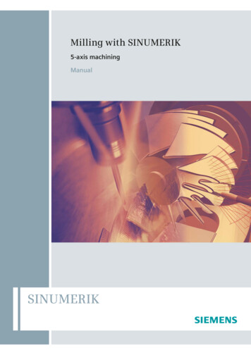
System overviewSystem overview2The SINUMERIK 808D is an economical CNC solution for milling and turning machines. Theturning variant of the control system can control up to two feed axes and one spindle. Ifconfigured with a software option for the "additional axis" function, it can additionally controlan axis that serves as either a rotary axis or a linear axis. The milling variant of the controlsystem can control up to three feed axes and one spindle.The following diagram shows a system configuration example for the SINUMERIK 808Dcontrol system:11), 12): For detailed information on cable shield connection, refer to Section "Analog spindle interface - X54 (Page 33)".13): For detailed information on cable shield connection, refer to Section "Pulse drive interfaces - X51, X52, X53 (Page 30)".Electrical Installation ManualOperating Instructions, 01/2015, 6FC5397-2EP10-0BA011
System overviewNOTICEUsing a copper protective earth conductor with a cross section of 10 mm2 to connect thePE terminal of V60 to the protective earth. For the NC and 24 VDC power supply, there areno special requirements of the cross section of the copper protective earth conductor. Forthe inverter or servo spindle drive, it is recommend to refer to the relevant specifications toconfirm the cross section of the copper protective earth conductor.LegendNameOrder number1)PPU141.1, turning6FC5370-1AT00-0AA0 (English)6FC5370-1AT00-0CA0 (Chinese)PPU141.1, milling6FC5370-1AM00-0AA0 (English)6FC5370-1AM00-0CA0 (Chinese)2)MCP6FC5303-0AF35-0AA0 (English)6FC5303-0AF35-0CA0 (Chinese)3)Setpoint cable (PPU141.1 to CPM60.1)6FC5548-0BA00-1AF0 (5 m)6FC5548-0BA00-1AH0 (7 m)6FC5548-0BA00-1BA0 (10 m)4)SINAMICS V60 Controlled Power Module 6SL3210-5CC14-0UA0 (4 A)(CPM60.1)6SL3210-5CC16-0UA0 (6 A)6SL3210-5CC17-0UA0 (7 A)6SL3210-5CC21-0UA0 (10 A)5)1FL5 motor1FL5060-0AC21-0AA0 (4 Nm, with key,without brake)1FL5060-0AC21-0AG0 (4 Nm, without key,without brake)1FL5062-0AC21-0AA0 (6 Nm, with key,without brake)1FL5062-0AC21-0AG0 (6 Nm, without key,without brake)1FL5064-0AC21-0AA0 (7.7 Nm, with key,without brake)1FL5064-0AC21-0AG0 (7.7 Nm, without key,without brake)1FL5066-0AC21-0AA0 (10 Nm, with key,without brake)1FL5066-0AC21-0AG0 (10 Nm, without key,without brake)1FL5060-0AC21-0AB0 (4 Nm, with key,with brake)1FL5060-0AC21-0AH0 (4 Nm, without key,with brake)1FL5062-0AC21-0AB0 (6 Nm, with key,with brake)1FL5062-0AC21-0AH0 (6 Nm, without key,with brake)1FL5064-0AC21-0AB0 (7.7 Nm, with key,with brake)Electrical Installation Manual12Operating Instructions, 01/2015, 6FC5397-2EP10-0BA0
Safety instructionsLegendNameOrder number1FL5064-0AC21-0AH0 (7.7 Nm, without key,with brake)1FL5066-0AC21-0AB0 (10 Nm, with key,with brake)1FL5066-0AC21-0AH0 (10 Nm, without key,with brake)6)Setpoint cable (PPU141.1 to inverter orservo spindle drive)6FC5548-0BA05-1AD0 (3 m)6FC5548-0BA05-1AF0 (5 m)6FC5548-0BA05-1AH0 (7 m)6FC5548-0BA05-1BA0 (10 m)7)Power cable (unshielded)6FC5548-0BA05-1CA0 (20 m)6FX6002-5LE00-1AD0 (3 m)6FX6002-5LE00-1AF0 (5 m)6FX6002-5LE00-1AH0 (7 m)8)Brake cable (unshielded)6FX6002-5LE00-1BA0 (10 m)6FX6002-2BR00-1AD0 (3 m)6FX6002-2BR00-1AF0 (5 m)6FX6002-2BR00-1AH0 (7 m)9)Encoder cable (shielded)6FX6002-2BR00-1BA0 (10 m)6FX6002-2LE00-1AD0 (3 m)6FX6002-2LE00-1AF0 (5 m)6FX6002-2LE00-1AH0 (7 m)10)Inverter or servo spindle drive (with analog interface)6FX6002-2LE00-1BA0 (10 m)From Siemens or a third-party manufacturerSystem structureThe structure of the SINUMERIK 808D control system is shown as follows: CNC Unit– Panel Processing Unit (PPU)– Machine Control Panel (MCP)– Setpoint cable to SINAMICS V60– Setpoint cable to the spindle Drive unit– SINAMICS V60 (for controlling feed axes)– 1FL5 motor– Power cable– Encoder cable– Brake cable (for motors with brake)– Inverter or servo spindle drive (for controlling the spindle)– Spindle motor– Spindle encoder Electronic handwheelsA maximum of two handwheels can be connectedElectrical Installation ManualOperating Instructions, 01/2015, 6FC5397-2EP10-0BA013
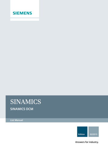
System overviewCabinet grounding guideNote that the PE/PEN busbar in the cabinet must connect to the ground through a grounding cable with a cross section 10 mm2as illustrated below.Electrical Installation Manual14Operating Instructions, 01/2015, 6FC5397-2EP10-0BA0
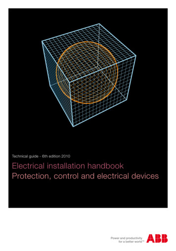
3Connecting3.1Interface overviewInterface overview on the Panel Processing Unit (PPU)Figure 3-1LegendInterface layoutInterfaceComment①X100, X101, X102Digital inputs②X200, X201Digital outputsRearElectrical Installation ManualOperating Instructions, 01/2015, 6FC5397-2EP10-0BA015
Connecting3.1 Interface overviewLegendInterfaceComment③X21FAST I/O④X301, X302Distributed I/O⑤X10Handwheel inputs⑥X60Spindle encoder interface⑦X54Analog spindle interface⑧X2RS232 interface⑨X51, X52, X53Pulse drive interfaces⑩X30USB interface, for connection with the MCP⑪X1Power supply interface, 24V DC power supply⑫-Battery interface⑬-Slot for the System CompactFlash Card (CF card)-USB interfaceFront⑭NoteThe rated output current of all the digital outputs is 250 mA.Interface overview on the Machine Control Panel (MCP)Figure 3-2LegendInterface layoutInterfaceCommentX10USB interface, for connection with the PPURear①Electrical Installation Manual16Operating Instructions, 01/2015, 6FC5397-2EP10-0BA0
Connecting3.2 Connection Overview for SINUMERIK 808D3.2Connection Overview for SINUMERIK 808DElectrical Installation ManualOperating Instructions, 01/2015, 6FC5397-2EP10-0BA017
Connecting3.2 Connection Overview for SINUMERIK 808DNote The 24 V signal of X200 must be connected; otherwise, the communication between thePPU and the drives does not function as it should. For the turning variant, connection to X52 is optional and depends upon whether you usethe software option "additional axis". If you desire to configure the control system tocontrol a rotary axis or an additional linear axis, connect X52 to a SINAMICS V60 whichconnects to a servo motor.Electrical Installation Manual18Operating Instructions, 01/2015, 6FC5397-2EP10-0BA0
Connecting3.3 Connecting the interfaces on the PPU3.3Connecting the interfaces on the PPU3.3.1Digital input interfaces - X100, X101, X102TypeMini Combicon 10-pinCableMax. length: 10 mMax. cross-section:One cable per connection: 0.5 mm2InputsPermissible level (including ripple)High level: 18 V - 30 VLow level: -3 V - 5 VTable 3- 1IllustrationPin assignment of X100 (DIN0)PinSignalComment1N.C.Not assigned2I0.0Digital input3I0.1Digital input4I0.2Digital input5I0.3Digital input6I0.4Digital input7I0.5Digital input8I0.6Digital input9I0.7Digital input10MExternal groundElectrical Installation ManualOperating Instructions, 01/2015, 6FC5397-2EP10-0BA019
Connecting3.3 Connecting the interfaces on the PPUTable 3- 2InterfaceTable 3- 3InterfacePin assignment of X101 (DIN1)PinSignalComment1N.C.Not assigned2I1.0Digital input3I1.1Digital input4I1.2Digital input5I1.3Digital input6I1.4Digital input7I1.5Digital input8I1.6Digital input9I1.7Digital input10MExternal groundPin assignment of X102 (DIN2)PinSignalComment1N.C.Not assigned23I2.0I2.1Digital inputDigital input45I2.2I2.3Digital inputDigital input67I2.4I2.5Digital inputDigital input89I2.6I2.7Digital inputDigital input10MExternal groundElectrical Installation Manual20Operating Instructions, 01/2015, 6FC5397-2EP10-0BA0
Connecting3.3 Connecting the interfaces on the PPUConnectingEnd sleeves are necessary if you use two cables per connection.Fasten the cables to the screw terminals and plug the terminals into interfaces X100, X101and X102 correctly.3.3.2Digital output interfaces - X200, X201TypeMini Combicon 10-pinCableMax. length: 10 mMax. cross-section:One cable per connection: 0.5 mm2OutputsTable 3- 4IllustrationRated digital output current: 250 mAPin assignment of X200 (DOUT0)PinSignalComment1 24V 24V input (20.4 - 28.8 V); must be connected2Q0.0Digital output3Q0.1Digital output4Q0.2Digital output5Q0.3Digital output6Q0.4Digital output7Q0.5Digital output8Q0.6Digital output9Q0.7Digital output10MExternal ground; must be connectedNote:The 24 V power supply must be connected even if X200 is not used;otherwise, the communication between the PPU and the drives does notfunction as it should.Electrical Installation ManualOperating Instructions, 01/2015, 6FC5397-2EP10-0BA021
Connecting3.3 Connecting the interfaces on the PPUTable 3- 5Pin assignment of X201 (DOUT1)IllustrationPinSignalComment1 24V 24V input (20.4 - 28.8 V)2Q1.0Digital output3Q1.1Digital output4Q1.2Digital output5Q1.3Digital output6Q1.4Digital output7Q1.5Digital output8Q1.6Digital output9Q1.7Digital output10MExternal groundConnectingEnd sleeves are necessary if you use two cables per connection.Fasten the cables to the screw terminals and plug the terminals into interfaces X200 andX201 correctly.3.3.3Fast input/output - X21TypeMini Combicon 10-pinCableShielded cableMax. length: 10 mMax. cross-section:One cable per connection: 0.5mm2InputsPermissible level (including ripple)High level: 18 V - 30 VLow level: -3 V - 5 VElectrical Installation Manual22Operating Instructions, 01/2015, 6FC5397-2EP10-0BA0
Connecting3.3 Connecting the interfaces on the PPUTable 3- 6IllustrationPin assignment of X21 (FAST I/O)PinSignalComment1 24 V 24 V input (20.4 - 28.8 V)2NCRDY 1NCRDY contact 13NCRDY 2NCRDY contact 24DI1Digital input5DI2Digital input6BERO SPINDLE or DI3Spindle bero or digital input7DO1Fast output8CWSpindle rotating clockwise9CCWSpindle rotating counter-clockwise10MGroundConnectingYou can connect the FAST I/O to the inverter to control the spindle rotating direction(unipolar):NC readiness is in the form of a relay contact (NO). It must be integrated into anEMERGENCY STOP circuit. The connection diagram is shown as follows:Electrical Installation ManualOperating Instructions, 01/2015, 6FC5397-2EP10-0BA023
Connecting3.3 Connecting the interfaces on the PPUConnection cablesEnd sleeves are necessary if you use two cables per connection.Fasten the cables to the screw terminals and plug the terminal into the interface X21.You can buy the shielded cables from a third-party manufacturer.3.3.4Distributed I/O - X301, X302Pin assignmentType50-pin socketInputsPermissible level (including ripple)High level: 18 V - 30 VLow level: -3 V - 5 VOutputsRated digital output current: 250 mAElectrical Installation Manual24Operating Instructions, 01/2015, 6FC5397-2EP10-0BA0
Connecting3.3 Connecting the interfaces on the PPUTable 3- 7Pin assignment of X301 (DISTRIBUTED I/O 1)PinSignalCommentPinSignal1MEXTExternal ground26I5.7Digital input2 24V 24V output27-Not assigned3I3.0Digital input28-Not assigned4I3.1Digital input29-Not assigned5I3.2Digital input30-Not assigned6I3.3Digital input31Q2.0Digital output7I3.4Digital input32Q2.1Digital output8I3.5Digital input33Q2.2Digital output9I3.6Digital input34Q2.3Digital output10I3.7Digital input35Q2.4Digital output11I4.0Digital input36Q2.5Digital output12I4.1Digital input37Q2.6Digital output13I4.2Digital input38Q2.7Digital output14I4.3Digital input39Q3.0Digital output15I4.4Digital input40Q3.1Digital output16I4.5Digital input41Q3.2Digital output17I4.6Digital input42Q3.3Digital output18I4.7Digital input43Q3.4Digital output19I5.0Digital input44Q3.5Digital output20I5.1Digital input45Q3.6Digital output21I5.2Digital input46Q3.7Digital output22I5.3Digital input47 24V 24V Input23I5.4Digital input48 24V 24V Input24I5.5Digital input49 24V 24V Input25I5.6Digital input50 24V 24V Input1)CommentElectrical Installation ManualOperating Instructions, 01/2015, 6FC5397-2EP10-0BA025
Connecting3.3 Connecting the interfaces on the PPUTable 3- 8Pin assignment of X302 (DISTRIBUTED I/O 2)PinSignalCommentPinSignal1MEXTExternal ground26I8.7Digital input2 24V 24V output27-Not assigned3I6.0Digital input28-Not assigned4I6.1Digital input29-Not assigned5I6.2Digital input30-Not assigned6I6.3Digital input31Q4.0Digital output7I6.4Digital input32Q4.1Digital output8I6.5Digital input33Q4.2Digital output9I6.6Digital input34Q4.3Digital output10I6.7Digital input35Q4.4Digital output11I7.0Digital input36Q4.5Digital output12I7.1Digital input37Q4.6Digital output13I7.2Digital input38Q4.7Digital output14I7.3Digital input39Q5.0Digital output15I7.4Digital input40Q5.1Digital output16I7.5Digital input41Q5.2Digital output17I7.6Digital input42Q5.3Digital output18I7.7Digital input43Q5.4Digital output19I8.0Digital input44Q5.5Digital output20I8.1Digital input45Q5.6Digital output21I8.2Digital input46Q5.7Digital output22I8.3Digital input47 24V 24V Input23I8.4Digital input48 24V 24V Input24I8.5Digital input49 24V 24V Input25I8.6Digital input50 24V 24V Input1)CommentMake sure that the current at pin 2 of X301 or X302 does not exceed the maximum currentIout 0.25 A; otherwise, the controller could be destroyed.1)ConnectingDANGERThe 24 V power supply must be protective extra low voltage in accordance with EN602041, Section 6.4, PELV (with M ground).Electrical Installation Manual26Operating Instructions, 01/2015, 6FC5397-2EP10-0BA0
Connecting3.3 Connecting the interfaces on the PPUCAUTIONBe sure not to connect the pin 2 of X301/302 to ground; otherwise, the CNC controller orthe power supply could be damaged!NoteThe 24 V output of X301/302 pin 2 comes from pins 47 to 50.NoteAddressing rangesX301: IB3, IB4, IB5, QB2, QB3X302: IB6, IB7, IB8, QB4, QB5NoteThe connecting cable between the power source, load current supply connection, andassociated reference potential M must not exceed the maximum permissible length of 10 m.Digital inputsThe diagram below shows you how to connect the connector pins of the digital inputs atinterface X301 (example). You can connect connector X302 in the same way.NoteWhen using an external power supply, you must connect the 24V (permissible range: 20.4 28.8 V) power supply for the digital outputs to all the four power input pins (X301, X302: pins47, 48, 49, 50).Electrical Installation ManualOperating Instructions, 01/2015, 6FC5397-2EP10-0BA027
Connecting3.3 Connecting the interfaces on the PPUDigital outputsThe diagram below shows you how to connect the connector pins of the digital outputs atinterface X301 (example). You can connect connector X302 in the same way.To supply the digital outputs, you must connect an external 24 V DC power supply (X301,X302: pins 47, 48, 49, 50).You must also connect the reference ground of the external power supply to X301, X302: Pin1 (MEXT).CAUTIONYou must ensure that the max. current consumption at pin 47, pin 48, pin 49, or pin 50 doesnot exceed 1 A.NoteYou must connect the 24 V power supply for the digital outputs to all the four power inputpins (X301, X302: pins 47, 48, 49, 50).External power supplyWhen using an external power supply for the digital inputs, you must connect the referenceground to X301, X302: Pin 1 (MEXT).Electrical Installation Manual28Operating Instructions, 01/2015, 6FC5397-2EP10-0BA0
Connecting3.3 Connecting the interfaces on the PPU3.3.5Handwheel inputs - X10Pin assignmentTypeMini Combicon 10-pinCableMax. length: 3mTable 3- 9Pin assignment of X10IllustrationPinSignalComment1A1TRACK A, handwheel 12A1 NNEGATIVE TRACK A, handwheel 13B1TRACK B, handwheel 14B1 NNEGATIVE TRACK B, handwheel 15 5V 5V power output6MGround7A2TRACK A2, handwheel 28A2 NNEGATIVE TRACK A2, handwheel 29B2TRACK B2, handwheel 210B2 NNEGATIVE TRACK B2, handwheel 2ConnectingYou are allowed to connect at most 2 electronic handwheels at connector X10 on the PPU.The handwheels must meet the following requirements:Transmission procedureSignals5V square wave signals (TTL level or RS422)Track A as a true and negative signal (Ua1Ua1)Track B as a true and negative signal (Ua2Ua2)Max. input frequency500 kHzPhase shift between Track A to Track 90o 30oBSupply5V, max. 250 mAElectrical Installation ManualOperating Instructions, 01/2015, 6FC5397-2EP10-0BA029
Connecting3.3 Connecting the interfaces on the PPU3.3.6Pulse drive interfaces - X51, X52, X53Pin assignmentTypeSub-D, 15-pin, maleCableType: drive cableMax. length: 10mIllustrationPinSignalComment1PULSE PULSE, to drive side2DIR DIREC
Electrical Installation Manual 8 Operating Instructions, 01/2015, 6FC5397-2EP10-0BA0 Mechanical installation DANGER Death or serious injury from electric shock The equipment which is not disconnected from the mains or properly protected contains hazardous vol