Transcription
CHAPTER 1COMMON MAINTENANCE TOOLS AND THEIR USESTools are designed to make a job easier and enableyou to work more efficiently. If they are not properlyused and cared for, their advantages are lost to you.toolbox is not actually at the work site, it should belocked and stored in a designated area.Regardless of the type of work to be done, you musthave, choose, and use the correct tools in order to doyour work quickly, accurately, and safely. Without theproper tools and the knowledge of how to use them, youwaste time, reduce your efficiency, and may even injureyourself.NOTEAn inventory list is kept in every toolbox tobe checked before and after each job ormaintenance action, to ensure that all tools areavailable to do your work, and to ensure thatthey are accounted for after you havecompleted your work.This chapter explains the specific purposes, correctuse, and proper care of the more common tools you willencounter as an ABE. Also discussed briefly are otheraids to maintenance, such as blueprints and schematics.USE EACH TOOL ONLY FOR THE JOB IT WASDESIGNED TO DO. Each particular type of tool has aspecific purpose. If you use the wrong tool whenperforming maintenance or repairs, you may causedamage to the equipment you're working on or damagethe tool itself. Remember, improper use of tools resultsin improper maintenance. Improper maintenanceresults in damage to equipment and possible injury ordeath to you or others.TOOL WORK HABITSLEARNING OBJECTIVES: Describe theTool Control Program. List several good toolwork habits."A place for everything and everything in its place"is just good common sense. You can't do an efficientrepair job if you have to stop and look around for eachtool you need. The following rules will make your jobeasier and safer.SAFE MAINTENANCE PRACTICES. Alwaysavoid placing tools on or above machinery or anelectrical apparatus. Never leave tools unattendedwhere machinery or aircraft engines are running.NEVER USE DAMAGED TOOLS. A batteredscrewdriver may slip and spoil the screw slot, damageother parts, or cause painful injury. A gauge strainedout of shape will result in inaccurate measurements.KEEP EACH TOOL IN ITS PROPER STOWAGEPLACE. All V-2 divisions have incorporated a ToolControl Program as directed by the Aircraft Launchand Recovery Equipment Maintenance Program(ALREMP).Remember, the efficiency of craftsmen and thetools they use are determined to a great extent by theway they keep their tools. Likewise, they are frequentlyjudged by the manner in which they handle and care forthem. Anyone watching skilled craftsmen at worknotices the care and precision with which they use thetools of their trade.The Tool Control Program is based on the conceptof a family of specialized toolboxes and pouchesconfigured for instant inventory before and after eachmaintenance action. The content and configuration ofeach container is tailored to the task, work center, andequipment maintained. Work center containers areassigned to and maintained within a work center. Otherboxes and specialized tools are checked out from thetool control center (tool room).The care of hand tools should follow the samepattern as for personal articles; that is, always keephand tools clean and free from dirt, grease, and foreignmatter. After use, return tools promptly to their properplace in the toolbox. Improve your own efficiency byorganizing your tools so that those used mostfrequently can be reached easily without diggingthrough the entire contents of the box. Avoidaccumulating unnecessary junk.KEEP YOUR TOOLS IN GOOD CONDITION.Protect them from rust, nicks, burrs, and breakage.KEEP YOUR TOOL ALLOWANCE COMPLETE. When you are issued a toolbox, each toolshould be placed in it when not in use. When the1-1
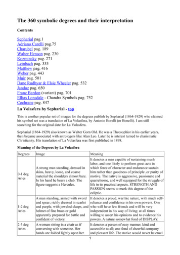
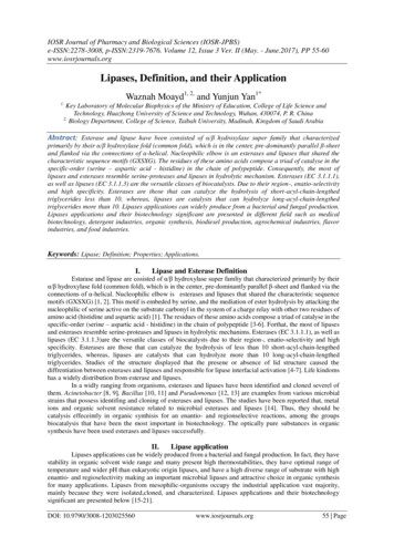
Other safety shoes are designed for use wheredanger from sparking could cause an explosion. Suchdanger is minimized by elimination of all metallic nailsand eyelets and by the use of soles that do not causestatic electricity.REVIEW QUESTIONSQ1.Describe the Tool Control Program.Q2.List several good tool work habits.Q3.What are inspection mirrors used for?GOGGLESCARE OF HAND TOOLSProper eye protection is of the utmost importancefor all personnel. Eye protection is necessary becauseof hazards posed by infrared and ultraviolet radiation,or by flying objects such as sparks, globules of moltenmetal, or chipped concrete and wood. These hazardsare ever-present during welding, cutting, soldering,chipping, grinding, and a variety of other operations. Itis IMPERATIVE for you to use eye protection devices,such as helmets, face shields, and goggles (fig. 1-1),during eye-hazard operations.LEARNING OBJECTIVES: List severalprinciples that apply to the care of hand tools.Tools are expensive; tools are vital equipment.When the need for their use arises, common sense plusa little preventive maintenance prolongs theirusefulness. The following precautions for the care oftools should be observed: Clean tools after each use. Oily, dirty, and greasytools are slippery and dangerous to use. NEVER leave tools scattered about. When theyare not in use, stow them neatly on racks or intoolboxes.Appropriate use of goggles will limit eye hazards.Some goggles have plastic lenses that resist shatteringupon impact. Others are designed to limit harmfulinfrared and ultraviolet radiation from arcs or flames byuse of appropriate filter lenses. Apply a light film of oil after cleaning to preventrust on tools.Remember, eye damage can be excruciatinglypainful. PROTECT YOUR EYES. INVENTORY tools after use to prevent loss.GLOVES NEVER hammer with a wrench.Use gloves whenever you are required to handlerough, scaly, or splintery objects. Special flameproofgloves are designed for gas and electric-arc welding tolimit danger and damage from sparks and other hotflying objects (fig. 1-2). Personnel in the electricalfields are usually required to wear insulating rubbergloves.REVIEW QUESTIONQ4.List several principles that apply to the careof hand tools.PERSONAL SAFETY EQUIPMENTLEARNING OBJECTIVES: Identify thetypes of personal safety equipment.Be sure to follow all regulations prescribed for theuse of gloves. Gloves must not be worn around rotatingmachinery unless sharp or rough material is beinghandled. If such is the case, EXTREME CARESHOULD BE EXERCISED to prevent the gloves frombeing caught in the machinery.To protect you from danger, protective equipmentsuch as safety shoes, goggles, hard hats, and gloves areissued. The use of this equipment is mandatory oncertain jobs. Their use is a MUST, and there is noquestion about that. Be sure to USE THEM on any jobWHERE they are REQUIRED. They can protect youfrom a lot of harm.SAFETY BELTS AND STRAPSThe safety strap and body belt shown in figure 1-3are what might be called your extra hands when youwork aloft. The body belt, strapped around your waist,contains various pockets for small tools. The safetystrap is a leather or neoprene-impregnated nylon beltwith a tongue-type buckle at each end. While you areclimbing you will have the safety strap hanging by bothends from the left ring (called a D-ring because of itsSAFETY SHOESSome safety shoes are designed to limit damage toyour toes from falling objects. A steel plate is placed inthe toe area of such shoes so that your toes are notcrushed if an object impacts there.1-2
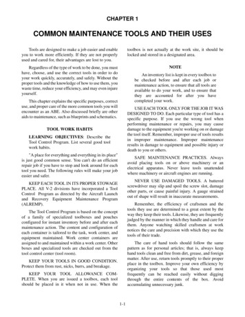
Figure 1-1.—Eye-protection devices.be placed around any part of a structure that is beingremoved.shape) on the body belt. When you are at workingposition, you unsnap one end of the safety strap, pass itaround the supporting structure so there is no danger ofits slipping (at least 18 inches from the top of the part onwhich it is fastened), and hook it to the right D-ring onthe body belt.Before placing your weight on the strap, determineVISUALLY that the snap and D-ring are properlyengaged. Do not rely on the click of the snap-tongue asan indication that the fastening is secure.The safety strap must be placed around a part of thestructure that is of sufficient strength to sustain an ABsweight and his or her equipment, and must rest flatagainst the surface without twists or turns. It must notThe body belt and safety strap require inspectionbefore use. Look for loose or broken rivets; cracks,cuts, nicks, tears or wear in leather; broken or otherwisedefective buckles, such as enlarged tongue-holes,defects in safety-belt snap hooks and body belt D-rings.If you discover any of these or other defects, turn inyour equipment and replace it.Perform maintenance periodically according toapplicable procedures. Remember that leather andnylon belts are treated in different manners.Figure 1-2.—Gas and electric-arc welding gloves.Figure 1-3.—Safety equipment.1-3
The title block also includes the name and addressof the Government agency or organization preparingthe drawing, the scale, drafting record, authentication,and the date (fig. 1-4).REVIEW QUESTIONQ5.Identify the different types of personal safetyequipment.A space within the title block with a diagonal orslant line drawn across it indicates that the informationusually placed in it is not required or is given elsewhereon the drawing.MAINTENANCE AIDSLEARNING OBJECTIVES: Read andinterpret blueprints, drawings, diagrams, andother maintenance aids.Revision BlockAs an ABE you will be required to read blueprintsand drawings during the performance of manymaintenance actions required to maintain theoperational readiness of the catapults and the arrestinggear engines. As you advance in rating you may also berequired to make sketches and drawings, which willassist you in the training of less-experiencedmaintenance personnel by making it possible for themto visualize the system or object you are explaining.The revision block (not shown) is usually located inthe upper right corner of the blueprint and is used forthe recording of changes (revisions) to the print. Allrevisions are noted in this block and are dated andidentified by a letter and a brief description of therevision. A revised drawing is shown by the addition ofa letter to the original number in the title block, asshown in figure 1-4, view A. If the print shown in figure1-4, view A, was again revised, the letter in the revisionblock of the title block would be replaced by theletter B.BLUEPRINTS AND DRAWINGSBlueprints are exact copies of mechanical or othertypes of drawings and employ a language of their own.It is a form of sign language or shorthand that useslines, graphic symbols, dimensions, and notations toaccurately describe the form size, kind of material,finish, and construction of an object. It can be said thatblueprint reading is largely a matter of translating theselines and symbols into terms of procedure, materials,and other details needed to repair, maintain, or fabricatethe object described on the print.Drawing NumberAll blueprints are identified by a drawing number(NAVSHIP Systems Command No. in view A of fig.1-4, and FEC Drawing No. in view B), which appears ina block in the lower right corner of the title block. Itmay be shown in other places also; for example, nearthe top border line in an upper corner, or on the reverseside at both ends so that it will be visible when adrawing is rolled up. If a blueprint has more than onesheet, this information is included in the blockindicating the sheet number and the number of sheets inthe series. For example, note that in the title blocksshown in figure 1-4 the blueprint is sheet 1 of 1.Usually you can look at a blueprint and recognizethe object if you are familiar with the actual part. Butwhen you are required to make or check on a certainpart, the applicable blueprint must be referred to inorder to get dimensions and other pertinentinformation. The important thing is to know what thedifferent symbols stand for and where to look for theimportant information on a blueprint. Some of theimportant facts listed on all blueprints are discussed inthe following paragraphs.Reference NumbersReference numbers that appear in the title blockrefer to numbers of other blueprints. When more thanone detail is shown on a drawing, a dash and a numberare frequently used. For example, if two parts areshown in one detail drawing, both prints would have thesame drawing number, plus a dash and an individualnumber, such as 8117041-1 and 8117041-2.Title BlockThe title block is located in the lower right corner ofall blueprints and drawings prepared according tomilitary standards. The block contains the drawingnumber, the name of the part or assembly that theblueprint represents, and all information required toidentify the part or assembly.In addition to appearing in the title block, the dashand number may appear on the face of the drawings,near the parts they identify. Some commercial printsshow the drawing and dash number, and point with aleader line to the part; others use a circle, 3/8 inch in1-4
Figure 1-4.—Blueprint title blocks. (A) Naval Ship's Systems Command; (B) Naval Facilities Engineering Command.Drawing Linesdiameter, around the dash number, and carry a leaderline to the part.The lines used in working drawings are more than ameans of showing a picture of an object for the purposeof building or repairing. The way a line is drawn has adefinite meaning.A dash and number are used to identify modified orimproved parts, and also to identify right-hand andleft-hand parts. Many aircraft parts on the left-hand sideof an aircraft are exactly like the corresponding parts onthe right-hand side but in reverse. The left-hand partsare usually shown in the drawing.Thick lines are used for the visible outline of theobject being drawn. Medium lines are used for thedotted lines representing hidden features and rnate-position lines. Center lines, dimension lines,long-break lines, ditto lines, extension lines, andsection lines are represented by thin lines.Above the title block on some prints you may see anotation such as "159674 LH shown; 159674-1 RHopposite." Both parts carry the same number. But thepart called for is distinguished by a dash and number.(LH means left-hand, and RH means right-hand.) Somecompanies use odd numbers for right-hand parts andeven numbers for left-hand parts.To understand blueprint reading, you must knowthe different types of lines used in general drawingpractice and the information conveyed by each. Someof the lines of major importance are illustrated in1-5
of blueprint shows the position, location, and use of thevarious parts of the ship; for example, to find thebattlestations sickbay, barbershop, or other parts of theship. In addition to plan views, other blueprints, calledassembly prints, unit or subassembly prints, and detailprints, show various kinds of machinery andmechanical equipment.figures 1-5-A and 1-5-B. The correct uses areillustrated in figure 1-6.Blueprints make it possible to understand, in acomparatively small space, what is to be made orrepaired. Of the many types of blueprints you will useaboard ship, the simplest one is the plan view. This typeFigure 1-5-A.—Standard lines.1-6
Figure 1-5-B.—Standard lines—continued.with its dimensions and all the information needed tomake a new part as a replacement. Assembly andsubassembly prints may be used to learn operation andmaintenance of machines, systems, and equipment.Assembly prints show the various parts of themechanism, how the parts fit together, and their relationto each other. Subassembly prints show the location,shape, size, and relationships of the parts of thesubassembly or unit. Detail prints show a single part1-7
PHANTOM LINECENTER LINEEXTENSION LINEDIMENSION LINELEADER LINEASECTIONING LINEBREAK LINEOUTLINEASECTION - AAHIDDEN LINECUTTING PLANE LINEABEf0175Figure 1-6.—Use of standard lines.MICROFILM/APERTURE CARDSElectricalMany prints and drawings are procured in the formof 16- and 35-mm microfilm. Microfilm prints anddrawings are available mounted on aperture (viewer)cards, as well as in roll form. A reader or some type ofprojector is required to enlarge the microfilm forreading. Activities are provided with a microfilmreader-printer, which as its name implies, enlarges themicrofilm for reading and also has the capability ofprinting a working copy in a matter of a few seconds.Schematic diagrams are also used to depictelectrical systems. They are basically the same as theCOOLING PANEL98710PMicrofilm greatly reduces the size of otherwisebulky files, which is very important aboard ship.PM.C.653SCHEMATIC DIAGRAMSSchematic diagrams show by means of single linesand symbols how the parts of a system are connectedfor the operation of the g diagrams are normally used to trace pipingsystems and their functions without actually describingthe shape, size, or location of the components or parts.Each component is represented by a symbol; and oncethese symbols are learned, the piping schematicdiagram is easy to read.1FIREMAIN1.2.3.4.5.Figure 1-7 is a good example of a piping diagram.As may be seen from this example, diagrams do notindicate the location of individual components withinthe station, but do locate the components with respectto each other within the system.6.Cutout valve.7.Reducing valveThrottling valve. 8.9.Relief valve.10.Test gauge.ABEf0176Hytrol valve.Pilot valve.Inlet lines.Discharge lines.Pressure gage.11. Orifice.12. Scuppervalve.13. Hosevalves.Figure 1-7.—Typical piping schematic for saltwater cooling.1-8
piping diagrams except they use electrical symbolsinstead of piping symbols. Figure 1-8 is an example ofan electrical system schematic.Schematic diagrams are especially helpful whenyou are learning a hydraulic system or pinpointing amalfunction in an electrical system. For moreinformation on diagrams, drawings, and blueprints, andtheir interpretation, study Blueprint Reading andSketching, NAVEDTRA 12014.BL15GGRRTSRSW#3HIGHTSRB125B124LEARNING OBJECTIVES: Identify thedifferent types of metal-cutting tools. Describethe uses of different types of cutting tools.Many types of metal-cutting tools are used byskilled mechanics of all ratings. As you become betteracquainted with the ABE rating, you will probablydiscover many tools that you use for cutting metal thatare not described in this text. In this text, only the basichand metal-cutting tools will be considered.MSW#1 SW#2HIGH LOWB120TSRMETAL-CUTTING TOOLSB131B122B126S3HIGH LOWHIGHB126B129BB TSRBAL8 BAL4B121BL2B127TSRB108B107LS2TSRB111B106BAL11 BAL10B113B110B109PS1ROne of the handiest tools for cutting light (up to1/16-inch thick) sheet metal is the hand snip (tip snips).The STRAIGHT HAND SNIPS, shown in figure R1LS3B101S1115 VOLTS, 60 L5WBAL1TSRBAL7GSnips and shears are used for cutting sheet metaland steel of various thickness and shapes. Normally, theheavier or thicker materials are cut by shears.B112GBAL3SNIPS AND SHEARSB114RWhere is the title block located on allblueprints and drawings prepared to militarystandards?B123SW#4LOWB130S4LOWQ6.BAL12 BAL14 BAL13 BAL15BAL15BL21BL1ABEf0177BL2BL26TSRCR2P1BL25REVIEW QUESTIONFigure 1-8.—Electrical system schematic.Figure 1-9.—Metal snips.1-9
have blades that are straight and cutting edges that aresharpened to an 85-degree angle. Snips like this can beobtained in different sizes, ranging from the small,6-inch, to the large, 14-inch, snip. Tin snips will alsowork on slightly heavier gauges of soft metals, such asaluminum alloys.Snips will not remove any metal when a cut ismade. There is danger, though, of causing minute metalfractures along the edges of the metal during theshearing process. For this reason, it is better to cut justoutside the layout line. This procedure will allow you todress the cutting edge while keeping the material withinrequired dimensions.Figure 1-10.—Cutting an inside hole with snips.Cutting extremely heavy gauge metal alwayspresents the possibility of springing the blades. Oncethe blades are sprung, hand snips are useless. Whencutting heavy material, use the rear portion of theblades. This procedure not only avoids the possibilityof springing the blades but also gives you greatercutting leverage.final cut just outside the layout line. This will permityou to see the scribed line while you are cutting and willcause the scrap to curl up below the blade of the snips,where it will be out of the way while the complete cut isbeing made.To make straight cuts, place the sheet metal on abench with the marked guideline over the edge of thebench and hold the sheet down with one hand. With theother hand, hold the snips so that the flat sides of theblades are at right angles to the surface of the work. Ifthe blades are not at right angles to the surface of thework, the edges of the cut will be slightly bent andburred. The bench edge will also act as a guide whenyou are cutting with the snips. The snips will force thescrap metal down so that it does not interfere withcutting. Any of the hand snips may be used for straightcuts. When notches are too narrow to be cut out with apair of snips, make the side cuts with the snips and cutthe base of the notch with a cold chisel.Many snips have small serrations (notches) on thecutting edges of the blades. These serrations tend toprevent the snips from slipping backwards when a cut isbeing made. Although this feature does make the actualcutting easier, it mars the edges of the metal slightly.You can remove these small cutting marks if you allowproper clearance for dressing the metal to size. Thereare many other types of hand snips used for specialjobs, but the snips discussed here can be used for almostany common type of work.Cutting Sheet Metal with SnipsIt is hard to cut circles or small arcs with straightsnips. There are snips especially designed for circularcutting. They are called CIRCLE SNIPS,HAWKS-BILL SNIPS, TROJAN SNIPS, and AVIATION SNIPS (fig. 1-9).To cut large holes in the lighter gauges of sheetmetal, start the cut by punching or otherwise making ahole in the center of the area to be cut out. With anaviation snips, or some other narrow-bladed snips,make a spiral cut from the starting hole out toward thescribed circle, as shown in figure 1-10, and continuecutting until the scrap falls away.To cut a disk in the lighter gauges of sheet metal,use a combination snips or a straight-blade snips, asshown in figure 1-11. First, cut away any surplusmaterial outside the scribed circle, leaving only anarrow piece to be removed by the final cut. Make theFigure 1-11.—Cutting a disk out of sheet metal.1-10
distance between the two pins that hold the blade inplace.Safety and CareLearn to use snips properly. They should always beoiled and adjusted to permit ease of cutting and toproduce a surface that is free from burrs. If the bladesbind or if they are too far apart, the snips should beadjusted. Remember the following safety tips:Hacksaw blades are made of high-grade tool steel,hardened and tempered. There are two types, theall-hard and the flexible. All-hard blades are hardenedthroughout, whereas only the teeth of the flexibleblades are hardened. Hacksaw blades are about1/2-inch wide, have from 14 to 32 teeth per inch, andare from 8 to 16 inches long. The blades have a hole ateach end, which hooks to a pin in the frame. Allhacksaw frames, which hold the blades either parallelor at right angles to the frame, are provided with awingnut or screw to permit tightening or removing theblade. Never use snips as screwdrivers, hammers, orpry bars. They break easily. Do not attempt to cut heavier materials than thesnips are designed for. Never use tin snips to cuthardened steel wire or other similar objects.Such use will dent or nick the cutting edges ofthe blades.The SET in a saw refers to how much the teeth arepushed out in opposite directions from the sides of theblade. The four different kinds of set are theALTERNATE set, DOUBLE ALTERNATE set,RAKER set, and WAVE set. Three of these are shownin figure 1-13. Never toss snips in a toolbox where the cuttingedges can come into contact with other tools.This dulls the cutting edges and may even breakthe blades. When snips are not in use, hang them on hooksor lay them on an uncrowded shelf or bench.The teeth in the alternate set are staggered, one tothe left and one to the right throughout the length of theblade. On the double alternate set blade, two adjoiningteeth are staggered to the right, two to the left, and soon. On the raker set blade, every third tooth remainsstraight and the other two are set alternately. On thewave (undulated) set blade, short sections of teeth arebent in opposite directions.HACKSAWSHacksaws are used to cut metal that is too heavy forsnips or bolt cutters. Thus, metal bar stock can be cutreadily with hacksaws.There are two parts to a hacksaw: the frame and theblade. Common hacksaws have either an adjustable or asolid frame (fig. 1-12). Most hacksaws found in theNavy are of the adjustable-frame type. Adjustableframes can be made to hold blades from 8 to 16 incheslong, while those with solid frames take only the lengthblade for which they are made. This length is theUsing HacksawsThe hacksaw is often used improperly. Although itcan be used with limited success by an inexperiencedperson, a little thought and study given to its proper usewill result in faster and better work and in less dullingand breaking of blades.Good work with a hacksaw depends not only uponthe proper use of the saw but also upon the properFigure 1-13.—"Set" of hacksaw-blade teeth.Figure 1-12.—Hacksaws.1-11
Figure 1-16.—Proper way to hold a hacksaw.Place the material to be cut in a vise. A minimum ofoverhang will reduce vibration, give a better cut, andlengthen the life of the blade. Have the layout lineoutside of the vise jaw so that the line is visible whileyou work.Figure 1-14.—Selecting the proper hacksaw blade.selection of the blades for the work to be done. Figure1-14 will help you select the proper blade to use whensawing metal with a hacksaw. Coarse blades, withfewer teeth per inch, cut faster and are less likely tochoke up with chips. However, finer blades, with moreteeth per inch, are necessary when thin sections arebeing cut. The selection should be made so that, as eachtooth starts its cut, the tooth ahead of it will still becutting.The proper method of holding the hacksaw isdepicted in figure 1-16. See how the index finger of theright hand, pointed forward, aids in guiding the frame.When cutting, let your body sway ahead and backwith each stroke. Apply pressure on the forward stroke,which is the cutting stroke, but not on the return stroke.From 40 to 50 strokes per minute is the usual speed.Long, slow, steady strokes are preferred.To make the cut, first install the blade in thehacksaw frame (fig. 1-15) so the teeth point away fromthe handle of the hacksaw. (Hand hacksaws cut on thepush stroke.) Tighten the wingnut until the blade isdefinitely under tension. This helps make straight cuts.For long cuts, rotate the blade in the frame so thatthe length of the cut is not limited by the depth of theframe. Hold the work with the layout line close to thevise jaws, raising the work in the vise as the sawingproceeds.To remove a frozen nut with a hacksaw, saw into thenut, as shown in figure 1-17, starting the blade close tothe threads on the bolt or stud and parallel to one face ofthe nut, as shown in view A. Saw parallel to the boltuntil the teeth of the blade almost reach the lockwasher.Lockwashers are hard and will ruin hacksaw blades, sodo not try to saw them. View B shows when to stopsawing. Then, with a cold chisel and hammer, removethis one side of the nut completely by opening the sawFigure 1-17.—Removing a frozen nut with a hacksaw.Figure 1-15.—Installing a hacksaw blade.1-12
kerf. Put an adjustable wrench across this new flat andthe one opposite, and again try to remove the frozennut. Since very little original metal remains on this oneside of the nut, the nut will either give or break awayentirely and permit its removal.To saw a wide kerf in the head of a cap screw ormachine bolt, fit the hand hacksaw frame with twoblades side by side, and with teeth lined up in the samedirection. With slow, steady strokes, saw the slotapproximately one-third the thickness of the head of thecap screw, as shown in figure 1-18. Such a slot willpermit subsequent holding or turning with ascrewdriver when it is impossible, due to close quarters,to use a wrench.Hacksaw SafetyThe main danger in using hacksaws is injury toyour hand if the blade breaks. The blade will break iftoo much pressure is applied, when the saw is twisted,when the cutting speed is too fast, or when the bladebecomes loose in the frame. Additionally, if the work isnot tight in the vise, it will sometimes slip, twisting theblade enough to break it.Figure 1-19.—Types of points on metal-cutting chisels.The type of chisel most commonly used is the flatcold chisel, which serves to cut rivets, split nuts, chipcastings, and cut thin metal sheets. The cape chisel isused for special jobs like cutting keyways, narrowgrooves, and square corners. Round-nose chisels makecircular grooves and chip inside corners. Finally, thediamond-point is used for cutting V-grooves and sharpcorners.CHISELSChisels are tools that can be used for chipping orcutting metal. They are made from a good grade of toolsteel and have a hardened cutting edge and beveledhead. Chisels are classified according to the shape oftheir points, and the width of the cutting edge denotestheir size. The most common shapes of chisels are theflat (cold chisel), cape, round nose, and diamond point(fig. 1-19).As with other tools, there is a correct technique forusing a chisel. Select a chisel that is large enough forthe job. Be sure to use a hammer that matches thechisel; that is, the larger the chisel, the heavier thehammer. A heavy chisel will absorb the blows of a lighthammer and will do v
hand tools clean and free from dirt, grease, and foreign matter. After use, return tools promptly to their pr