Transcription
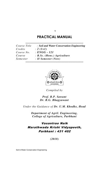
1PRACTICAL -------------------------------Course TitleCreditsCourse No.CourseSemester: Soil and Water Conservation Engineering: 2 (1 1): ENGG - 121: B.Sc. (Hons.) Agriculture: II Semester ------------------------------Compiled byProf. B.P. SawantDr. R.G. BhagyawantUnder the Guidance of Dr. U.M. Khodke, HeadDepartment of Agril. Engineering,College of Agriculture, ParbhaniVasantrao NaikMarathwada Krishi Vidyapeeth,Parbhani : 431 402(2018)Soil & Water Conservation Engineering
2PRACTICAL NO. 1TITLE : GENERAL STATUS OF SOIL CONSERVATION IN INDIASoil degradation in India is estimated to be occurring on 147 million hectares ofland which includes; 94 Mha from water erosion, 16 Mha from acidification, 14 Mha from flooding, 9 Mha from wind erosion, 6 Mha from salinity, and 7 Mha from a combination of factors.The causes of soil degradation are both natural and human-induced. Naturalcauses include earthquakes, tsunamis, droughts, avalanches, landslides, volcaniceruptions, floods, tornadoes, and wildfires. Human-induced soil degradation results fromland clearing and deforestation, inappropriate agricultural practices, impropermanagement of industrial effluents and wastes, over-grazing, careless management offorests, surface mining, urban sprawl, and commercial/industrial development.Inappropriate agricultural practices include excessive tillage and use of heavy machinery,excessive and unbalanced use of inorganic fertilizers, poor irrigation and watermanagement techniques, pesticide overuse, inadequate crop residue and/or organiccarbon inputs, and poor crop cycle planning. Some underlying social causes of soildegradation in India are land shortage, decline in per capita land availability, economicpressure on land, land tenancy, poverty, and population increase.Effects of Soil Erosion in India Soil erosion results in huge loss of nutrients in suspension or solution, which arewashed away from one place to another, thus causing depletion or enrichment ofnutrients. Besides the loss of nutrients from the topsoil, There is also degradation through the creation of gullies and ravines. Water causes sheet-wash, surface gullies, tunnels and scours banks in rivers. In hot and dry climate of India, wind blowing is the main cause of soil erosion.Indian government is adopting adequate measures to reduce the unpleasant effectsof soil erosion in India particularly in the states like Punjab, Maharashtra, Karnataka.Soil & Water Conservation Engineering
3Introduction to Soil Conservation:Soil and water conservation is essential to protect the productive lands of theworld. In our country, where droughts, famines and floods cause crop damage almostevery year, soil conservation will not only increase crop yields but also prevent floodsand further deterioration of land.Prior to the days of independence, while general problems of soil erosion wereknown, answers to them backed by scientific investigations were not known.Consequently, during the framing of the first year plan and early in the second five yearplan, a chain of 9 Soil Conservation Research Demonstration and Training Centres wereestablishedSoil & Water Conservation Engineering
4Broad objectives of these Centre’s are:(i) To identify erosion problems and conservation of land and water resources underdifferent land use systems,Soil & Water Conservation Engineering
5(ii) To evolve mechanical and biological methods of erosion control under different landuse systems,(iii) To evolve methods of control of erosion and reclamation of ravines stabilization oflandslides and hill torrents,(iv) To evaluate hydrological behavior and evolve techniques of watershed managementunder different systems,(v) To set up demonstration projects for popularizing soil and water conservationmeasures,(vi) To impart specialized training in soil and water conservation to gazetted and nongazetted officers of State Governments.Important Soil and Water Conservation Programmes implemented by state andcentral Govt. Soil conservation in catchments of river valley project (RVP). Integrated Watershed Management in the catchments of flood Prone Rivers(FPR). Centrally Aided Drought Prone Area Development Program (DPAP), (as per1995 guidelines) implemented by Government and NGO. DesertDevelopment Programme ( DDP) National Watershed Development Program for Rain fed Area (NWDPRA)implemented by Dept. of Soil Conservation & Watershed Management,Gov.M with financial support from Department of Agriculture, Gov.I Operational Research Projects on Integrated Watershed Management (ICAR) World Bank Project on Watershed Development in Rain fed Area. Council for Peoples Action & Rural Technology (CAPART) supported 38Watershed Development Programs in Maharashtra DPAP & IWDP projects (of 2001 guidelines) in Satara, Sangali& NasikDistricts of Maharashtra state. NABARD Holistic Watershed Development Programme Vasundhara Watershed Development Project Maharashtra government has launched a new programme named‘JalyuktaShivarAbhiyan’ in a state on January 26, 2015. The programme aimto make 5000 villages free of water scarcity every year and to conserve andprotect the soil from further degradation. This Abhiyan aims at initiatingpermanent measures to make the state drought free by 2019 and to harvestrain water within the village boundary thereby increasing ground water levels.Soil & Water Conservation Engineering
6PRACTICAL NO. 2TITLE: STUDY OF SURVEYING INSTRUMENTSInstruments for measuring distance1.ChainA) Metric Surveying Chains-20 meter or 30 meterB) Non Metric Surveying Chains i) Gunter’s Chain2.Arrows3.Tapesii) Revenue Chainiii) Engineer’s Chaini)Cloth or Linen Tape ii)Woven Metallic Tapeiii)Metric Steel TapeInvar Tape v) Synthetic Tape4.Wooden pegs5.Ranging rods6.Ranging poles7.Offset rod8.Laths9.Whites10.Plumb bob11.Open cross-staff12.Optical squareiv)1. Chain – The chain is composed of 100 or 150 pieces of galvanized mild steel wire 4mm in diameter (8 s.w.g.) called links. The length of each link is 20 cm (0.2 m). The endsof each link are bent into a loop and connected together by means of three oval rings,which afford flexibility to the chain. The ends of the chain are provided with brasshandles for dragging the chain on the ground, each with a swivel joint so that the chaincan be turned round without twisting. The outside of the handle is the zero point or theend point of the chain. The length of the chain is measured from the outside of one handleto the outside of the other. The length of a link is the distance between the centers of thetwo consecutive middle rings. The end links include the handles. Metallic tags orindicators of distinctive pattern called tallies are fixed at various distinctive points of thechain to facilitate quick reading of fractions of a chain in surveying measurements. (DrawFigure)Soil & Water Conservation Engineering
7A) Metric Surveying Chain:The chains are made in lengths of 20 and 30 meters. To enable the reading offractions of a chain without much difficulty, tallies (tags) are fixed at every five metrelength and small brass rings are provided at every metre length except where tallies areattached. To facilitate holding the arrows in position with the handle; a groove is cut on theoutside surface of the handle. The handles are joined to link by swivel joint. The talliesused for marking the distances in a metric chain are marked with letters ‘m’.B) Non Metric Surveying Chainsi) Gunter’s chains – The Gunter’s chain is 66 ft. long and divided into 100 linkseach of 0.66 ft. It is very convenient for measuring distances in miles and furlongs andfor measuring land when the unit of area is an acre on account of its simple relation tomile and acre. 10 Gunter’s chain equals 1 furlong, 80 Gunter’s chain equal to a mile and10 Square Gunter’s chain 1 acre.ii) Revenue Chain – The revenue chain is commonly used for measuring fields incadastral survey. It is 33 ft. Long and divided into 16 links. One Square revenue chainequals one guntha.iii) Engineers’ Chain – The engineers’ chain is 100 ft. long and is divided into100 links each one-foot in length. It is used on all engineering surveys. The distancesmeasured with the engineers’ chain are recorded in feet and decimals.2. Arrows- Arrows are also called marking or chaining pins and are used to mark the endof each chain during the process of chaining. They are made of good quality hardenedsteel wire 4 mm (8 s.w.g.) in diameter. The arrow are made 400 mm in length pointed atone end for inserting into ground and bent into a ring at the other end for facility ofcarrying. (Draw Figure)3. Tapes Cloth and Linen Tape – Used for taking subsidiary measurements, such asoffsets. It is very light and handy. It is easily affected by damp. If wet, it shrinks.It stretches easily and likely to twist.Soil & Water Conservation Engineering
8 Metric Woven Metallic Tape - They are available in 2, 5, 10, 20, 30 and 50metres. The tape is made of yarn and metal wire. A metal ring is attached to theouter end of tapes. The length of the tape includes the metal ring. At everycentimetre a black line 8 to 10 mm in height is drawn. Every five centimetres ismarked with an arrow in black. Every decimetre and meter is marked with a backline extending over the full width of the tape (i.e.16 mm). The graduation marksat every decimetre and meter are numbered with black and red figures,respectively. Metric Steel Tape - Tape is available in 1, 2, 10, 30 and 50 meters. The tape isof steel or stainless steel. The outer end is provided with a ring. The length of thetape includes the metal ring. The tape is marked legible with a line at every fivemillimetres, centimetres, decimetres and metre. Every decimetres and metre shallbe marked with Hindu Arabic numbers in bold. When button release device ispressed, the tape automatically rewinds into case. Invar tape - For highest precision work, the invar tape is used. It is made of analloy of steel and nickel (36 %). It is 6 mm wide and may be obtained in lengthsof 30 m, 50 m and 100 m. It is not calibrated throughout its length but hasterminal lines. Each terminal division has ten 1 mm divisions. It is veryexpensive. Synthetic Tape – These tapes are manufactured of glass fiber having PVCcoating. They are graduated every 10 mm and figured every 100 mm. Metrefigures are shown in red. They are convenient for measuring short lengths.4. Wooden Pegs - These are used to mark the positions of stations. They are made ofhard timber and tapered at one end. They are usually, 2.5 cm square and 15 cm long. Butin soft ground 40 to 60 cm long pegs and 4 to 5 cm square are suitable. They should bedriven in the ground with about 4 cm lengths projecting above the ground. (Draw Figure)5. Ranging rod - The ranging rods are used for marking the position of stations forranging the lines. They are made of well-seasoned straight-grained timber of teak. Theyare circular or octagonal in cross section of 3 cm nominal diameter. Lower shoe is 15 cmSoil & Water Conservation Engineering
9long. They are made of two sizes as 2 m and 3 m and are divided into each 0.2 m length.In order to make them visible from a distance they are painted alternately black and whiteor red and white. Now days instead of timber, mild steel hallow pipes are used. (DrawFigure)6. Ranging Poles - Similar to the ranging rods but are heavier. They vary in length from4 m to 6 m or more. Used in the case of very long lines.7. Offset Rods – Similar to the ranging rod. It is usually 3 m long and is divided intoparts each 0.2 m length. Top is provided with a open ring for pulling or pushing the chainthrough a hedge. It has two short narrow vertical slots. It is used for aligning the offsetline and measuring short offsets.8. Laths – Useful for ranging long lines. Also used over uneven ground when the rangingrod is not visible due to obstructions. They are light, cheap. Being white, they are easilyvisible at a great distance usually 1.0 m long.9. Whites – When the ranging rods are not available or insufficient whites are used.These are thin strip of bamboo and 40 cm to 1 m in length. One end is sharp and theother end is split for inserting pieces of white papers. They are also useful for temporarymarking of contour points.10. Plumb Bob - The plumb bob is required when measuring distance along slope totransfer point to the ground. It is also used far accurate centering over a station, and fortesting the verticality of ranging rod. (Draw Figure)11.Open cross-staff- It is a simple. It consists of two parts: - 1) the head; 2) the leg.The common type of cross staff consists of 4 metal arms with vertical slits for sightingthrough. The head is fixed to the top of an iron stand about 1 .2 to 1.5 m long this isdriven in to the ground.12.Optical square- An optional square is a compact hand instrument used in settingout right angles with greater accuracy than a cross staff. It consists of a circular box about5 cm in diameter and 1.25 cm deep in which two mirrors are fitted at right angles to theplane of instruments.Soil & Water Conservation Engineering
10PRACTICAL NO. 3TITLE : STUDY OF LEVELLING INSTRUMENTSInstruments Required: Dumpy level with stand, levelling staff, chain, or tape and alevel field book for recording staff readings, distances etc.Objectives:1. To study the parts of dumpy level.2. To study the setting up dumpy level3. To read the Leveling staff.Dumpy level: It is the most commonly used level. This instrument is short and stout,hence the name as dumpy.Parts of Dumpy level:1. Levelling head2.Telescope3. Eyepiece4. Diaphragm5. Focusing screw6.Ray shade7. Level tube nuts8.Level tube9. Cross bubble tube.Levelling Staff: It is telescopic pattern self-recoding staff, usually 4m long whenfully extended. The solid top length of 1.25 m long slides into central bore 1.25 mlong, which in turn slides into the lower or bottom box 1.5 m. Each length whenpulled out to its full length is held in position by means of a brass spring catch. Eachmetre is subdivided into 200 divisions, each division being 5 mm. The metre numeralis in red and marked to the right and the decimeter numeral in black and marked intothe left. The staff appears upside down when viewed through the telescope so that thereadings are taken from above downwards.Adjustments of the level: Two kinds 1.Temporary and 2. PermanentTemporary Adjustments: The temporary adjustments are those, which have to beperformed at each set up of the level. They are a) Setting up the level and b) Focusingthe eyepiece and object glass.Soil & Water Conservation Engineering
11 Setting up the level :i) Fixing the instrument on the tripod: Hold the instrument in the right hand and fixit on the tripod by turning round only the lower part with the left hand.ii) Leg adjustment: Place the instrument at convenient height for sighting with thetripod legs spread well apart a nearly as can be judged by the eye. Bring all footscrews in the center of their run. Fix any two legs firmly into the ground and movethird leg to the right or left until the bubble is approximately in the center. Then moveit in or out until the bubble of cross tube is approximately in the center. Finally the legshould be fixed in such a position that both bubbles are approximately in the center oftheir run.iii) Levelling up: Place the telescope parallel to any pair of foot screws and bring thebubble to the center of its run by turning these screws equally either both inwards oroutwards. Turn the telescope through 900 so that it lie over the third screw and centerthe bubble by turning this screw. Bring the telescope back to its original position.Again bring the bubble to the center of its run and repeat these operations until thebubble remains in the center of its run in both positions. If the instrument is inadjustment, the bubble will remain center for all directions of the telescope.iv) Focusing the eyepiece: Remove the lid of the object glass and hold a sheet ofwhite paper in front of it. Move the eyepiece in and out until the cross hairs aredistinctly seen.v) Focusing the object glass: Direct the telescope towards the staff and on lookingthrough the eyepiece, bring the image of the staff between the two vertical hairs orlines of the diaphragm. Adjust the objective by turning the focusing screw until theimage is clear and distinct.Reading the Staff:i) Having set up and levelled the instrument carefully, direct the telescope towardsthe staff held vertically on the staff station and focuses it.ii) Always bring the staff between the two vertical hairs/lines and always use theportion of the horizontal cross hair between them in reading the staff. Reading should beSoil & Water Conservation Engineering
12taken at intersection. First note the red figure, then the black figure and finally count thespaces. Record the reading in field book.Systems of taking out the reduced level of point from the staff reading:1. The Collimation System - It consist in finding the elevation of the plane ofcollimation (H.I.) for every set up of the instrument, and then obtaining the reduced levelof points with reference to the respective plane of collimation. Elevation of plane of collimation for the first set up of the level is determinedby adding back sight to R.L. of B.M. The R.L. of intermediate point and first change point are then obtained bysubtracting the staff reading taken on the these point (I.S. and F.S.) from theelevation of plane collimation. When the instrument is shifted to the second position a new plane ofcollimation is set up.The levels of the two planes of collimation arecorrelated by means of B.S. and F.S. on C.P. The elevation of this plane isobtained by adding the new B.S. taken on the C.P. from the second positionon the level to the R.L. of first C.P. The R.L. of successive point and secondC.P. are found by subtracting their staff readings from the elevation of thisplane of collimation.Arithmetical CheckThe difference between the sum of the back sights and the sum of the foresightsshould be equal to the difference between the first and last reduced level.B.S.- F.S. Last R.L. - First R.L.2. Rise and Fall SystemIt consists in determining the difference of level between consecutive points bycomparing each point after the first with that immediately preceding it. The differencebetween their staff reading indicates a rise or a fall according as the staff reading at thepoint is smaller or greater than that at the preceding point. The reduced level of eachpoint is then found by adding the rise to, or subtracting the fall from the reduced level ofthe preceding point.Soil & Water Conservation Engineering
13Arithmetical Check There are three checks on the accuracy of the reductions. The difference betweenthe sum of the back sights and the sum of the foresights the difference between the sumof the rises and that of the falls The difference between the first and last reduced levels.B.S. F.S. rise - fall Last R.L. - First R.L.Example:The following readings were taken successively with a level and levelling staff.0.250, 0.500, 0.300, 1.565, 2.150, 3.560, 0.450, 1.260. The level was shifted after 3rd and6th reading. Record these readings in the table and find out the reduced levels (RL) ofdifferent points. Assume RL of the first point as 100 m. Apply usual checks.Solution:1. The Collimation System (Height of instrument method)Station Staff ReadingB.S151.56599.7500.300 101.515 99.950 C.P2.1500.4506 Remarks100.250 100.00 B.M.0.5004R.L.F.S0.25023I.SH.I2.26599.365 C.P.3.560 98.40597.9551.26097.145 L.P5.12Arithmetical CheckThe difference between the sum of the back sights and the sum of the foresights Soil & Water Conservation Engineering
14The different between the first and last reduced levelsB.S. F.S. Last R.L. - First R.L.2.265-5.12 97.145 -100.002.855 2.8552. Rise and Fall SystemStation Staff ReadingB.SI.SRiseFall100.00 B.M.0.50021.56530.250 99.7500.300 0.2002.15040.45056 RemarksF.S0.2501R.L.2.26599.950 C.P0.585 99.365 C.P.3.5601.410 97.9551.2600.810 97.145 L.P5.120.200 3.055Arithmetical CheckThe difference between the sum of the back sights and the sum of the foresights the difference between the sum of the rises and that of the falls The difference betweenthe first and last reduced levelsB.S. F.S. rise - fall Last R.L. - First R.L.2.265-5.12 0.200- 3.055 97.145 -100.002.855 2.855 2.855Soil & Water Conservation Engineering
15PRACTICAL NO. 4TITLE : CHAIN TRIANGULATION SURVEYLand surveys are made to secure data for exact description of the boundaries of apiece of land, to determine its area, to secure necessary data for making a plan, to reestablish the boundaries of a piece of land which has been previously surveyed and todivide a piece of land into a number of units.There are two general methods of land surveying:1) Triangulation and2) Traversing1) TRIANGULATION SURVEY: - In triangulation survey, the lines of survey form anetwork of triangles. It is the system of surveying in which the area is divided into simplegeometrical figures and the work is carried out by taking its measurement.2) TRAVERSING: - A traverse survey is one in which frame work consists of series ofconnected lines, the lengths and directions are measured by chain or tape and with anangular instruments respectively. It is classified as – a) open traverse b) closed traverse.a) Open traverse: - It consists of series of lines but not returning to the startingpoint. Also it does not start and end at points whose positions on plan are known.b) Closed traverse:- It is said to be closed traverse, when a complete circuit is madei.e. when it returns to the original position and forms a closed polygon.The principle of chain surveying is triangulation. It is the simplest kind ofsurveying in which the sides of various triangles are measured directly in the field.FIELD SURVEY BY TRIANGULATION METHODPrinciple of Triangulation: A survey in which the given field or area is divided into number of suitabletriangles and measurement of all the sides of triangles is done is known as triangulationsurvey. Triangle is only a plain geometrical figure knowing the three sides of which it canSoil & Water Conservation Engineering
16be plotted exactly in size and shape. No angular measurement is required. For this surveyfield must be accessible and vision free stations.INSTRUMENTS & MATERIAL – Chain, tape, ranging rods, arrows and drawingmaterial.PROCEDURE:1. Erect ranging rods at all the corner point stations of the field.2. Prepare a rough figure of a field on a page of field book and divide this intonumber of suitable triangles. A suitable triangle is that in which no angle is too acute orobtuse i. e. not less than 30º and not more than 120º.3. By direct ranging measure the lengths of all the sides of all the triangles andnote down the measurements in a field book and also on a rough drawing.OBSERVATION TABLESr. No.Line1234567891011Soil & Water Conservation EngineeringLength (m)Remarks
17PLOTTING:1. Select a suitable scale for the preparation of a plan taking into consideration thesize of paper and field measurements.2. With this selected scale, plot one side of any triangle. With the same scale drawtwo arcs by a compass from the ends of this side, equal to the lengths of remaining sidesof a triangle. The intersection of these two arcs fixes the third station. Join this stationwith the ends of the side. A triangular portion of a field is plotted.3. Construct next triangular portion by taking a suitable side of this triangle by thesame procedure. In this way plot all the triangular areas. After plotting all the triangularareas, plan of field is obtained.CALCULATION OF AREA OF A FIELD:For calculation of area of a field, calculate individual areas of all the triangles by asemi perimeter formula which is as under:S a b c2Area of triangle S (S – a) (S – b) (S- c)a, b, and c are the three sides of any triangle. The sum of all the triangular areas is equalto total area of a field.Sr. No.Triangle1234567Total Area,m2Soil & Water Conservation EngineeringArea , m2
18PRACTICAL NO. 5TITLE: PLANE TABLE SURVEY (Radiation method)Objective: To measure the area of the field by using PTS (Plane Table Survey Method).Plane Table SurveyingPlane table is a graphical method of surveying in which the field works and theplotting is done simultaneously. It is particularly adopting in small mapping. Plane tablesurveying is used for locating the field computation of area of field.Merits: It is most suitable for preparing small scale map or surveying small area. It is most rapid method. Field book is not necessary. No great skill is required for satisfactory map. It is particularly suitable for magnetic area where prismatic compass is notreliable. Contour and irregular object may be represented accurately. It is less costly.Demerits: Plane Table Essentially a tropical instruments. It is not suitable to work in wet climate. There are several accessories to be carried out and therefore they are likely to belost. It is not suitable for accurate work.Instruments:Plane Table (drawing board), Alidade, Trough Compass, Spirit Level, Plumbingfork, Drawing Material, chain, arrows, ranging rods etc.1. Drawing board mounted on tripodA sheet of drawing paper, called plane table sheet is fastened to the board. Boardis made up of well-seasoned wood such as teak of size 40x30 to 75x60cm. it had planeand smooth top. It is mounted on a tripod in manner that it can be leveled. Leveling up ofthe table is done by shifting the legs of tripod. Some tripod provided with leveling screwor by ball and socket head for accurate leveling.Soil & Water Conservation Engineering
192. Alidade:Alidade consists of two vertical sight vane fitted at end the end of straightedge.The straight edge ruler usually made of brass or teak wood graduated beloved edge. Oneof the sight veins is provided with narrow slit and the other with a central vertical wire orhair. Beveled working edge alidade is called fiducial edge.3. A Through compass for marking the direction magnetic meridian on paper.4. Sprit level for leveling the table.5. Forked plumb for centering the table.6. Water proof cover to protect the sheet from rain.Setting up plane tableThe plane table is set approximately waist-high, so that the surveyor may bendover the board without resting against it. The plane table is set by following threeoperations at any station i.e. fixing, centering and orientation processes.Fixing:Table should be set at a convenient height for working. The legs of tripod standshould be spread apart and firmly fixed on the ground.Centering:It is the process of keeping the table over the station that the point on the paperrepresenting the station being occupied is vertically over the point on the ground. It isdone by forked plumb bob.Orientation:When the table has to be set up at more than one station it is necessary that it isoriented so that the lines on the paper remain parallel to the lie which they represent onthe ground. So orientation is “the process of keeping the table to the position which isoccupied at the first station”.Orientation is done by two methods: By use of the magnetic needle. Orientation by back sighting.Orientation by the magnetic needle:To orient the table at any subsequent station, the through compass(or circular boxcompass) is placed along the line representing the magnetic meridian which has beendrawn on the paper at the first station, and the board is then turned until the ends of theneedle o\are opposite the zeros of the scale. The board is then clamped in position. It issuitable for rough small scale mapping.Soil & Water Conservation Engineering
20Orientation by back sighting:This is the most accurate method of orientation and is always be preferred.Suppose a table is set up over station Q on the line PQ which has been previouslydrowned as PQ from station p. The alidade is placed along the line QP and board thenturned until the line of sight bisects the ranging rod at P. Board is then properly clamped.Methods of plane tabling1. Radiation:2. Intersection:3. Traversing:4. Resection:1. RadiationIn this position the point is located on plane by drawing a ray from the plane tablestation to the point, and plotting scale along the ray the distance is measured from thestation to the point. The method is suitable for the survey of the small areas which can becommanded from a single stationProcedure for Radiation plane table survey: Select appoint p so that all points to be located are visible from it. Set up the table at p and leveled. Marked the direction of magnetic meridian with through compass in top corner ofsheet. Select the point p on the sheet so that it is exactly over station p on the ground. Centering the Alidades on p, sight the various points A, B, C etc. and draw therays along edge of Alidades. Measure the distance PA, PB, PC etc. from p to various points with chain or tapeand plot them to scale along the corresponding rays. Join the points a, b, c, etc. togive outline of survey. Measure the sides of various triangles formed such way and calculate the areas ofdifferent triangles by semi perimeter formula. Add all areas to get total area of thefield.Soil & Water Conservation Engineering
21PRACTICAL NO. 6TITLE : ESTIMATION OF RUNOFF BY RATIONAL METHODRational Method:To design soil conservation structures with the proper capacity and to meet theneed of respective condition it is necessary to estimate peak runoff rate. There arenumber of formulae and methods for calculating the maximum rate of runoff for givenarea. The rational method is used for calculating the maximum rate of runoff for a givenarea. The rational method is commonly used in predicting peak runoff rate of smallwatershed. The rational formula proposed by C.E. Ramser is expressed in F.P.S. unit as
Course No. ENGG : - 121 Course B.Sc. (Hons.) Agriculture: Semester II Semester (New) : ----- Compiled by Prof. B.P. Sawant Dr. R.G. Bhagyawant Under the Guidance of Dr. U . To evolve mechanical and biological methods of erosion control under different land use systems, (iii) To evolve methods of control of erosion and reclamation of ravines .