Transcription
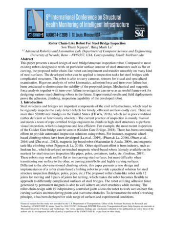
Roller Chain-Like Robot For Steel Bridge InspectionSon Thanh Nguyen1, Hung Manh La21,2Advanced Robotics and Automation Lab, Department of Computer Science and Engineering,University of Nevada, Reno – NV89557, USA, Corresponding Email: hla@unr.eduAbstractThis paper presents a novel design of steel bridge/structure inspection robot. Compared to mostexisting robots designed to work on particular surface contour of steel structures such as flat orcurving, the proposed roller chain-like robot can implement and transfer smoothly on many kindof steel surfaces. The developed robot can be applied to inspection tasks for steel bridges withcomplicated structures. The robot is able to carry cameras, sensors for visual and specializedexamination. Rigorous analysis of robot kinematics, adhesion force and turn-over failure hasbeen conducted to demonstrate the stability of the proposed design. Mechanical and magneticforce analysis together with turn-over failure investigation can serve as an useful framework fordesigning various steel climbing robots in the future. Experimental results and field deploymentsprove the adhesion, climbing, inspection capability of the developed robot.1. IntroductionSteel structures and bridges are important components of the civil infrastructures, which need tobe regularly inspected to early detect defects for timely, efficient and less costly cure. There aremore than 50,000 steel bridges in the United States (FHWA, 2016), which are in poor condition(either deficient or functionally obsolete). The current practice of inspection is mainly manualand needs a team of rope-certified bridge engineers to climb on high steel structures to performvisual inspection, which is dangerous and less efficient. For example, the most recent inspectionof the Golden Gate bridge can be seen in (Golden Gate Bridge, 2018). There has been continuingefforts to provide automated inspection solutions using robots. For instance, magnetic wheelbased climbing robots have been developed (La et al., 2019), (Pham & La, 2016), (Pham et al.,2016) and (Zhu et al., 2012), magnetic leg-based robot (Mazumdar & Asada, 2009), and magnetictank-like climbing robot (Nguyen & La, 2018). Other significant effort is from industry, such asInuktun Inc., which developed un-touched magnetic wheel-based robots (already available on themarket) for steel structure inspection like pipes, poles, containers, tanks, etc. (Inuktun, 2019).These robots may work well in flat or less curving steel surfaces, but meet difficulty whentransitioning one surface to the other, or passing joints/bolts and highly curving surfaces.Different to the abovementioned climbing robots, this paper presents a new design andimplementation of a roller chain-based climbing robot to provide a practical solution for steelstructure inspection (bridges, poles, pipes, etc.) The proposed roller chain-like robot with 12joints for moving and 3 pairs of joints for turning, which makes the robot becomes flexible toapproach to differently complicated surfaces of steel bridges. The robot utilizing adhesion forcegenerated by permanent magnets is able to well adhere on steel structures while moving. Theroller-chain design with 15 independently controlled joints allows the robot to work well on both flat,curving surfaces and transferring points and overcome obstacles. To demonstrate the robot’s workingprinciple, it has been deployed for wide range of surfaces and experimental conditions.Financial support for this study was provided by the U.S. Department of Transportation, Office of the Assistant Secretary for Research andTechnology (USDOT/OST-R) under Grant No. 69A3551747126 through INSPIRE University Transportation Center (http://inspire-utc.mst.edu) atMissouri University of Science and Technology. The views, opinions, findings and conclusions reflected in this publication are solely those of theauthors and do not represent the official policy or position of the USDOT/OST-R, or any State or other entity.
Proceedings9th International Conference on Structural Health Monitoring of Intelligent InfrastructureAugust 4-7, 2019 – St. Louis, Missouri (USA)2. Overall DesignThe overall design of theroller chain-like robot isdepicted in Fig. 1. Therobot consists of 12 jointsfor forward and backwardmoving; and three pairs ofjoints for controlling therobot’s direction.Fig 1. Overall design of robot for steel bridge inspection tasks.Kinematic structure of therobot is illustrated in Fig. 2. The robot moves by collaboration of 12 joint angles (1 to 12) thatare driven via 12 servo motors. For turning, when robot gets state like Fig. 3, joint pairs (1.1 and2.1) drive the robot turning left or right with 90 degrees range, in which, joints 1.1, 1.2 and 1.3are active joints while 2.1, 2.2 and 2.3 are passive-cardan joints. Cardan joints are necessary incase the active and passive joints are not coaxial when the robot turns. With three pairs, robotcan turn triple times per moving round. On each moving joint, there are two magnet blocks,which create adhesion force for the robot. The magnet blocks are integrated through the free jointsto help the robot approach every surface contour effectively by manipulating natural characteristic ofmagnet field. The surface with largest force will expose before approaching magnetic materials asFig. 4. The designed robot can work well on different surface contours as shown in Fig. 5.Fig 2. Robot kinematics.(a) Robot moves on flat surface.Fig 3. Robot turns left.(b) Robot tranfers betweentwo surfaces.Fig 4. Magnetstates beforeapproaching steelsurfaces.(c) Robot tranfers to other surface withobtacle.
Proceedings9th International Conference on Structural Health Monitoring of Intelligent InfrastructureAugust 4-7, 2019 – St. Louis, Missouri (USA)(d) Robot moves on curving surface.(e) Robot moves oncylinder steel surface.(f) Robot moves on circumferentialdirection of cylinder object.Fig 5. Robot’s locomotion on different surface contours.3. Magnetic Force AnalysisFig 6. a) Robot attachs verically to surface; b) Robot attachs horizontally tosurface.Fig 7. a) h max; b) h min.Let P be the robot’s total weight (P mg, where m is the robot’s mass, and g is the gravitationalacceleration). Let Fm be the magnetic adhesion force, and N be the reaction force. Let l1 to l4 bethe distance between first to last magnet block contacting to the surface to point O1 , and h be thedistance between the center of mass to the surface (Fig. 6(a)). Moment at point O1 is calculatedas follows:P*h M O P * h ( Fm1 * l1 Fm 2 * l2 Fm3 * l3 Fm 4 * l4 ) 0 Fmj l l l l .1234Fm1F In case 2, Fig. 6(b), F . Moment at point O2 is calculated as follows:m1am1b21 MO2P*h. P * h ( 4 Fm1a * a 4 Fm1b * b ) 0 Fmj 2 (a b)Following the proposed design, a 5.2 cm, b 0.635 cm, and l1 28.57 cm, l2 19.47 cm, l3 9.1cm, l4 1.27 cm:P*hP*h. l1 l2 l3 l4 2 ( a b )To avoid turn-over failure, the magnetic force of the magnet block: Fmj P*h.2(a b)
Proceedings9th International Conference on Structural Health Monitoring of Intelligent InfrastructureAugust 4-7, 2019 – St. Louis, Missouri (USA)In different locomotions, the robot shape can be changed as illustrating in Fig. 7, which led to theP * hmax(Fig. 7(a)). Therefore, to avoid both sliding and turn-overchange of h as well. Fmj 2(a b)failures, the robot’s magnetic force of each magnet block should satisfy: 2.5P P * hmax F ; .m j (j 1: n) max n 2(a b) (1)Following the proposed design, P 30 N, hmax 13 cm, n 4. 2.5*30 30*13Fm j (j 1: 4) max ;33.42(N) . 2*(5.2 0.635) 44. Motor Torque AnalysisPosition of magnet block is very important. It should be located in the position describing in Fig.8. In both cases, when i1 i (Fig. 9 and Fig. 10) the servo can not be optimal for the moment.- i i1 , we can see x x1 , whichmeans servo 4 bears moreload from Fm1, Fm 2, Fm 3, whenmoving.- i i1 , the arm is longer, whichmakes greater moment for theservo.Fig 8. Magnet block position analysis.In order to make the robot move, theforce created by the servo should winthe adhesion force of the last permanent magnet and the steel surface. As shown in Fig. 9, denoteM as the torque of one motor, Q is rotation fulcrum, and i is the arm from Fmj to Q. The requiredmoment is satisfied:M i i * Fmj(2)i 1.27 cm, selected magnet force Fmj 80 (N) satisfied condition (1). M i 101,6 (N.cm).Fig 9. Wheni i1 .Fig 10. Wheni i1 .5. Experiment resultsIn order to measure the adhesion force created by permanent magnet, we have setup anenvironment as follows. The robot’s body - whose mass is m 3kg - is placed on top of a flatsteel surface while it is connected to a scale through an inelastic wire. We create a pull force onto
Proceedings9th International Conference on Structural Health Monitoring of Intelligent InfrastructureAugust 4-7, 2019 – St. Louis, Missouri (USA)the scale trying to lift the robot off the surface (similar setup to Fig. 13 in Nguyen & La, 2018).At the time the robot is about to be off the surface, the force applied to the scale is equal to thesum of robot’s weight and the magnetic pull force. Denote Fpull as the force we applied onto thescale, M is the value shown on the scale while P is the weight of robot’s body, and Fmag is themagnetic force. With g 10m/s2, P mg 30N and Fpull Mg 10M, we can calculatemagnetic adhesion force as follows Fpull P Fmag Fmag 10M 3(N). The adhesion forcemasurement data is shown in Fig. 11-12.Fig 11. Adhesion force on flat surfaces.Fig 12. Adhesion force on curving surfaces with differentradii.From (1), the minimum adhesion force n* Fmj (theory) 4* 62.9 251,6 N. From (2), themaximun adhesion force of robot n* Fmj (selected) 4* 80 320 N as shown in Fig. 11-12.The climbing tests were performed on both steel structures and a steel bridge (Fig. 13-15). Inboth cases, the robot was able to adhere strongly on the steel surface during its motion.Fig 13. Climbing tests on steel structures. Video demonstration: https://ara.cse.unr.edu/?page id 11Fig 14. Climbing tests on a steel bridge at UNR’s campus: https://www.youtube.com/watch?v VoE4W5r no&feature youtu.be
Proceedings9th International Conference on Structural Health Monitoring of Intelligent InfrastructureAugust 4-7, 2019 – St. Louis, Missouri (USA)Fig 15. Climbing tests on paint-coasted steel structures.6. ConclusionsThe paper presents a new design of the climbing robot for steel bridge inspection and evaluation.The robot is designed following the roller-chain based concept in order to maximize theflexibility of the robot body. The proposed design allows the robot to climb smoothly ondifferent steel structures and pass the joints safely. The detail of mechanical design together withthe analysis of magnetic and motor forces has presented. Experimental results conducted on bothsteel structure and steel bridge have shown that the robot can adhere well on different steelsurfaces (flat, curving, paint coasted) while moving or passing the joints. In the future work, therobot will be equipped with robotic sensors (e.g., global positioning system, inertialmeasurement unit, infrared, hall-effect) for autonomous localization and safe navigation on thesteel structures. In addition, non-destructive evaluation sensors and visual camera will beintegrated with the robot for data collection and inspection of steel structures and bridges.ReferencesFHWA (2016). U.S. Department of Transportation Federal Highway Administration, “National bridgeinventory data,” Available at: http://www.fhwa.dot.gov/bridge/nbi.cfm, accessed January 30,2016.Golden Gate Bridge (2018). Crews inspect condition of golden gate bridge’s towers, April 30, Crews-Inspect-Condition-of-Golden-GateBridge s-Towers Bay-Area-481315951.html.Pham, H. N, La, M. H., Ha, Q. P, Dang, N. S., Vo, H. A, and Dinh, H. Q. (2016). Visual and 3d mappingfor steel bridge inspection using a climbing robot. In The 33rd Intern. Symposium on Automationand Robotics in Construction and Mining (ISARC), pages 1–8, July 2016.Pham, H. N., and La, M. H. (2016) Design and implementation of an autonomous robot for steel bridgeinspection. In 54th Allerton Conf. on Comm., Con., and Comp., pages 556–562, Sept 2016.La, M. H., Dinh, H. T., Pham, H. N., Ha, P. Q., and Pham, Q. A. (2018) Automated robotic monitoringand inspection of steel structures and bridges. Robotica, 37(5): 947–967, May 2019.A. Mazumdar and H. H. Asada (2009). Mag-foot: A steel bridge inspection robot. IEEE/RSJ InternationalConference on Intelligent Robots and Systems (IROS), pages 1691–1696, Oct 2009.Zhu, D., Guo, J., Cho, C., Wang, Y., and Lee, L. (2012). Wireless mobile sensor network for the systemidentification of a space frame bridge. IEEE/ASME Trans. on Mechatronics, 17(3):499–507, June2012.Nguyen, T. S., La, M. H. (2018). Development of a Steel Bridge Climbing Robot, Robotics (cs.RO),arXiv:1803.08209 [cs.RO], pp. 1-8, September, 2018.Inuktun (2019). Versatrax 150TM. Available at: http://inuktun.com/en/products/. Accessed on March 20th,2019.
Advanced Robotics and Automation Lab, Department of Computer Science and Engineering, University of Nevada, Reno – NV89557, USA, Corresponding Email: hla@unr.edu Abstract This paper presents a novel design of steel bridge/structure inspection robot. Comp