Transcription
ProfilometryNNUM thematic seminarAnalysisWednesday 10 May 2017Børge HolmeSINTEFborge.holme@sintef.no
Outline What is topography? Techniques for measuring topography White Light Interferometry (WLI) Atomic Force Microscopy (AFM) Summary: When to use which technique2
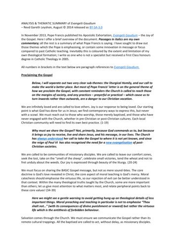
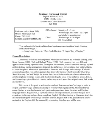
Topography100 kmNew Zealandand surrounding sea bed100 µmSurface of a tooth with an amalgam fillingTopography can be measured on different scales!3
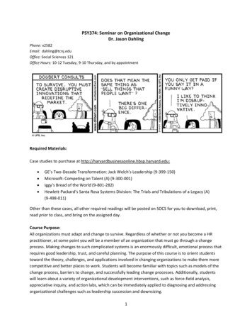
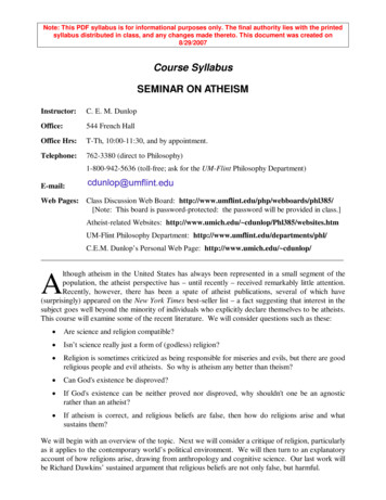
Vertical measurement rangeTechniques for measuring topography1m1 mmProjectedStripesStylusProfilometry1 cm1 µm1 nm1 pmAtomicForceMicroscopyOpticalProfilometry1 pm 1 nm 1 µm 1 mm1mLateral measurement range40.1 nm
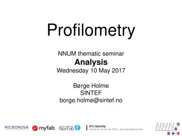
Profilometry (measuring topography) Stylus Profilometry 2D systems [Mitutoyo] 3D systems [Dektak]DektakSensofar5 Optical ProfilometryMitutoyome Chromatic Confocal Sensing [Stil, me] Confocal microscopy [Leica, Nikon] Focus variation [Sensofar] White Light Interferometry [Wyko, Zygo, Sensofar] Digital Holographic Microscopy [Lyncée Tec] etc.Nikon
Availability of instruments near youLocationStylus ProfilometerAtomic ForceMicrosopesOpticalProfilometerNTNU NanoLab Dektak 150Lund Nano Lab Dektak 6MChalmers (NFL) Tencor P15, Tencor AS500, DektakUppsala (MSL)Dektak 150, Dektak XTDanChipDektak 8, Dektak XTAUiODektakUSNDektakAaltoDektakXT, AlphaSINTEF6Dimension 3100Wyko NT1100and ICONWyko NT1100DimensionICON PTSensofarWyko NT1100DI MultiModeWyko NT9800
White Light Interferometry (WLI)WYKO (Veeco/Bruker) optical profiler7
Vertical Scanning Interferometry (VSI) Height range: Several millimeters Noise level (3 nm) too high for very flat surfaces8
Phase Shifting Interferometry (PSI) Low noise level (0.3 nm), good for flat surfaces Can not measure sharp steps9
WLI working principleCCDCameraBeam splitterWhite or greenLEDObjective lensUpper mirrorInterferometer{Lower mirrorSample surface10
Pixel size vs. Optical resolutionPixel size: 7.1 µmOptical res: 3.8 µmPixel size: 97 nmOptical res: 490 nmUndersampling:Pixels are larger thanoptical resolutionOversampling:Pixels are smaller thanoptical resolutionMagnification: 2.5*0.55x 1.4x11Magnification: 50*2x 100x
UndersamplingOversampling12
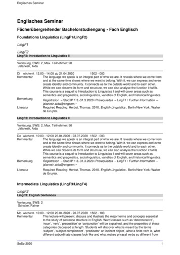
Limit for the surface steepness If a dark and bright fringe fills the same pixel, the average is greyso the interference is not detected. The practical maximum slope gives the steepest surface tilt thatcan be measured: arctan z / x arctan 134 nm / pixelsize Cylindrical sample surfaceIntensityPixel sizeon sampleBeginning of scan13Later in scan
Practical maximum slope between 2 and 35 You need a high-magnification lens to see steep facetsIf the surface has a high localroughness, you may be able tomeasure steeper slopes14
Wrong step height if different materialsBe careful when measuring Transparent materials on a substrate (May give reflections from both surfaces) Different materials within the same image (Phase changes upon reflection)Mo on Si:Measuring 169 nm stepCovering the samplewith gold: 56 nm stepHeight offset from material:hoffset 2 0 arctan 4 4 1 n S22n and are real part andimaginary part of refractive index15
Beware of artefacts near sharp stepsMeasured profileStep height profile displaybatwings due to Light diffraction Shadowing Light reflection Lateral translation/tiltingduring vertical scanning16A Harasaki, J Schmit & J C.Wyant,Applied Optics, 39, 2107-2115 (2000)Real profile
Atomic Force Microscopy (AFM)Live demo of intermolecular forces17
AFM working principlePiezo forvibration AFM with opticalmicroscope18Piezo forX, Y, Zscanningof sampleControllerPC
Cantileversand tipsParticle Ø 9 nm Many types exist,for differentapplicationsMagneticElectric19
Contact mode vs. Non-contact modehttp://perso.univlemans.fr/ pulsiveforces20Probingattractiveforces Contact mode used forhard surfaces Non-contact mode for softsurfaces or to detectsoftness contrast
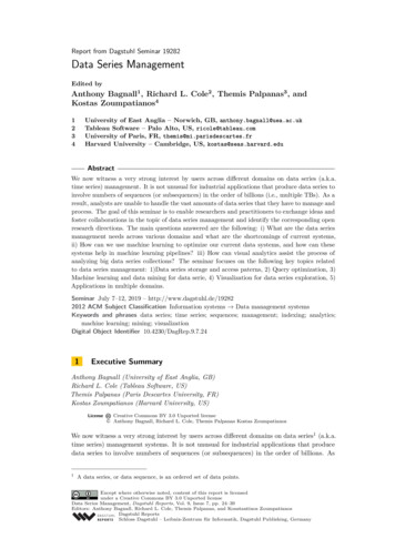
Non-contact mode gives bothTopography and Phase imagesTopographyPhaseDisplaying the same data in different ways: Can study individual dislocationsThe absolute height and its derivative21
AFMMeasuring topography22LFMMeasuring frictional forcesInterface Physics Group, Leiden Institute of PhysicsLateral Force Microscopy (LFM)
Lateral Force Microscopy (LFM)AFMLFMUseful fordistinguishingbetween h/polymer blends
Using AFM to study MEMS deviceHiVe Master student Huy Quoc Nguyen came to Oslo to use the AFMat SINTEF Materials and Chemistry24
Using AFM to study MEMS device25
WLI AFM on SAPO-34 catalyst grains SEM images show nearly cubic grains The shape can be related to the crystal structure26
WLI AFM on SAPO-34 catalyst grainsRelating the pentagonalgrowth spirals tostructural detailsBørge Holme, Pablo Cubillas, Jasmina Hafizovic Cavka, Ben Slater, Michael W. Anderson, Duncan AkporiayeGrowth mechanisms in SAPO-34 studied by White Light Interferometry and Atomic Force MicroscopyCrystal Growth & Design 10, 2824-2828 (2010)27doi: 10.1021/cg9016118
When to use which technique? Use AFM when you need to see lateral details 1 µm need info on surfacesoftness or friction need info on magnetic orelectrical properties want to interact physicallywith the sample28 Use WLI/Stylus when you want to measure roughsurfaces or step heights 10 nm want images larger than100 µm want fast imaging want easy quantificationof heights
Location Stylus Profilometer Atomic Force Microsopes Optical Profilometer NTNU NanoLab Dektak 150 Lund Nano Lab Dektak 6M Chalmers (NFL) Tencor P15, Tencor AS500, Dektak Dimension 3100 and ICON Wyko NT1100 Uppsala (MSL) Dektak 150, Dektak XT Wyko NT1100 DanChip Dektak 8, Dektak XTA Dim