Transcription
WWW.TGB-GROUP.COM1Slewing RingsTGBgroup
2
3
TGB GroupWith over 20 years of experience in bearings, gears and power transmission, the TGB Group has become a global leader in the development and production of movement solutions for the industrial andrenewable energy markets. The TGB Group has manufacturing facilities on different continents whichenables us to provide competitive solutions and customise projects while being able to retain a flexiblemanufacturing system and offer worldwide deliveries!Our aim is to forge long lasting relationships with our customers by demonstrating our commitmentthroughout the engineering process, by exceeding customer expectations, by providing excellent service and by offering the best value for money.Our knowledge and experience will enable you to make the right choice!TGB Group S.L.4
indexApplications .6Technical information .8Calculation and check . . .9Installation & maintenance .12E serie.14I serie.21SD serie.28U serie.32Z serie.33Accessories. 34Ed. 3 (FEB-17)5
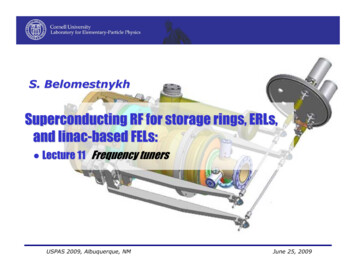
Application ExamplesRotary TablesFork LiftMobile Crane6
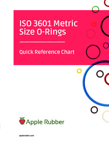
Application ExamplesMan LiftMachineryCranes7
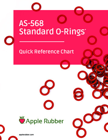
Slewing rings technical informationIntroductionSlewing rings are mechanical elements designed to withstand high loads (axial, radial and tilting moment) whileperforming rotational movements to displace the load. The axial loads are the ones applied on the same directionas the rotation axis, while the radial loads are perpendicular to this axis.The main parts of the slewing ring are two rotating rings and the rollingelements between them. Both rings are provided with holes for bolts thatcan be threaded or through holes to fix the part to the structure. All theslewing rings without teeth can be also ordered with inner teeth or outerteeth.The slewing ring load capability depends on its size and geometry andalso on the type and amount of the rolling elements. For each slewingring there is a load diagram that shows the maximum load that theslewing ring can withstand in terms of axial load and tilting moment.In order to choose the proper slewing ring for each application, please follow the procedure mentioned in thebelow flow chart:8
Slewing ring calculation and checkEquivalent load calculationFirst of all, the loads that the slewing ring will be supported have to be defined. To take into account the differencesbetween an application of high-precision and another one that receives high mechanical stress, different application factors must be considered. These are shown in the table below for different load cases.Table 1: Application factor depending on applicationTGBgroup recommends adding a safety factor to the loads, for greater caution, depending on the amount of working hours, the frequency at which the peak loads occur, etc. These factors will be applied in the axial load andtilting moment as follows:If the slewing ring is subjected to radial loads, a radial static factor must be considered. This factor is calculatedusing the following procedure:1. Calculate the ratio2. Calculate the load eccentricity characteristic using:3. Obtainfrom the graphs shown below:4. Apply this coefficient to the axial load and the tilting moment as follows:Once the equivalent axial load and tilting moment have been obtained, it is possible to start choosing the slewingring and check in the load chart whether it can withstand these loads or not.9
Slewing ring calculation and checkRacewayEach slewing ring has a corresponding load chart which shows the maximum axial load and tilting moment thatit is able to withstand (The load chart safety factor is 1). A slewing ring is correct for the application if the loadingpoint (combination between axial load and tilting moment) is below its load curve.The vertical axis represents the equivalent tilting moment and the horizontal axis indicates the equivalent axialload. The blue line indicates the load limit of the slewing ring considering the raceway while the green line showsthe load limit of the slewing ring screws. A slewing ring will be valid statically only if the point where intersect theequivalent axial force with equivalent tilting moment is below both lines.In case the maximum load occurs frequently during rotation movement or a dynamic study of the slewing ring isrequired, please contact with TGBgroup technical department for assistance. Usually the life of the slewing ring isaround 30000 load cycles. For highly demanding applications, vibration or shocks, it is recommended to contactthe technical department for a detailed calculation adapted to the application.ScrewsThere are some requirements regarding the screws that must be fulfilled to ensure that the limit bolt curve on theload charts is valid:- All the holes of the slewing ring must be used when assembling it to the structure.- All the holes must be tightened to the appropriate tightening torque (Table 2).- The limit bolt curve is only valid when the bolts are working under compression loads.- The bolt quality must be 10.9.- The threaded length of the bolt must be at least 1.5times the bolt diameter except when using nuts.- As a general rule, it is always considered an additional flange of 20mm thickness.- It is recommended a bolt length of 5times the bolt diameter.For pure radial loads we recommend contacting with the TGBgroup technical department to perform a more accurate study of the bolted union. In case the customer needs to ensure the union, for example for high vibrationapplications, we recommend the use of self-locking Nord-Lock washers or Loctite.10
Slewing ring calculation and checkFriction torqueAll the slewing rings need a minimum torque to turn the slewing ring that depends on the loads applied, thelubrication, the preload on the slewing ring and the use or not of spacers. This value can be calculated using thefollowing formulas:Ball Slewing ring:Roller Slewing ring:TeethFor the toothed slewing rings, the maximum turning torque of the slewing ring will be limited by the module, thetooth height and the pitch diameter. There is a possibility to harden the teeth with a heat treatment to increasethe maximum loads of the tooth a 20%.On the slewing ring tables two values of load on the teeth appear: the first one corresponds to the fatigue limitwhile the second one corresponds to the breaking limit. When a turning torque is given, the force that the toothshall withstand can be calculated with the next formula:For the choice of the pinion that will match the slewing ring, it must be taken into account that the pinion teethmust be higher than the slewing ring teeth (minimum difference tooth module).During installation of both parts, the clearance between flanks must be checked. This value has to be measuredon the most eccentric part of the slewing ring and it must not exceed 0,04*m (where m refers to the module).Slewing ring speedThe maximum linear speed at which the slewing ring can work is 2m/s at the raceway. For slewing rings on vertical position this speed is limited at 1m/s. The formula used to convert the linear speed in angular speed is theone following:Working temperatureThe temperature working range of a slewing is sent between -20ºC and 70ºC.11
Installation & maintenace instructionsTransport, Handling and StorageTransport only in horizontal position avoiding possible impacts. The slewing ring should be manipulated carefullyand wearing working gloves all the time. The threaded holes can be used to fix bolts to handle the slewing ringin a safety way with a hoisting device. Store always in horizontal position and in closed rooms. Keep it awayfrom getting wet. The corrosion protection has a shelf-life of approx. 3 months in closed packaging.InstallationPrevious to the installation, a cleaning of the slewing ring and the structure where is going to be mountedmust be done. During the cleaning process avoid the cleaning product to come inside the slewing ring. It is notallowed the cleaning of the slewing ring with steam high pressure systems.It should be checked that the slewing ring is fully supported by the structure. Install the slewing ring on themounting surface placing the filling plug for the balls (soft zone) at 90º from the main load zone. The slewing ringmust be mounted without any external loads. It is convenient to perform working tests in the structure before theloads are applied.The bolts used must be from the dimension, quantity and quality indicated. The slewing ring lifespan andfunctionality might be affected in case of non-compliance of the points mentioned above. TGBgroup recommends retightening the bolts after the first 3 months of operation at the appropriate tightening torque (Table 2).Table 2: Tightening torques for Metric mounting bolts (non-lubricated thread)LubricationSlewing rings are supplied with slewing ring raceway prelubricated. It is recommended to grease it again prior to initialoperation and re-lubricated accordingly, depending on workingconditions. The procedure to regrease consists in injectinggrease into all grease nipples one after the other while rotatingthe slewing ring until a bead of fresh grease appears in oneseal. For the toothed slewing rings, the contact area betweenteeth must also be greased, for example with a brush.12
Installation & maintenace instructionsThe slewing rings must be re-greased after each cleaning and also before and after large periods of inactivity, for example during the winter months for cranes and building machines. The reason for re-lubrication is toguarantee minimum properties of the grease. On the following table the re-lubrication intervals can be seen forguidance.The values on the table must never be a substitute for the values determined by the experience. The most usualcause for slewing ring failure is an insufficient amount of lubricationTable 3: Recommended re-lubrication intervals (only for guidance)Maintenance and security controlsTGBgroup recommends retightening the bolts to the prescribed torque after no more than 100 working hours tocompensate the possible settling. This should be done without external loads applied on the bolts union. Thisinspection should be repeated from then on every 3 months of work. The frequency of the inspection must bereduced under special working conditions.13
E.20.BBearing TypeDimensionsFixing holesGear teethDammUmmCmmDimmLammnanºLimmninºPmmTooth 2928,239,6777E.1200.20.00.B1198,1 1095,5 1092,510221135441048481184814828,239,691G Nº4 x Grease nipples DIN 71412 AM 8x1 equally-spacedFz norKNFz maxKNWeightKG24,93143Ask for a detailed drawing of the bearing, values may differ.14
E SeriesE.25.BDimensionsU IT8Bearing 553E.1100.25.00.B10964E.1200.25.00.B1198Fixing holesDi IT8CmmGear teethFz norKNFz 105495711163099530mmG Nº4 x Grease nipples DIN 71412 AM 8x1 equally-spacedMassznºLammmmTooth ForceWeightKGAsk for a detailed drawing of the bearing, values may differ.E.20.CBearing TypeDimensionsDammUmmCmmFixing holesGear teethDmmDimmLammnanºLimmninºPmmmTooth ForceznºFz norKNFz 00.C1198,4 1095,5 1092,510559841135221012201184814828,339,683G Nº4 x Grease nipples DIN 71412 AM 8x1 equally-spacedAsk for a detailed drawing of the bearing, values may differ.15
E SeriesE.32.CFixing holesDimensionsBearing TypeGear teethDaUCDDiLanaLiniPmmmmmmmmmmmmnºmmnºmmTooth ForceFz 12855,577,6200mzFz 6250G Nº6 x Grease nipples DIN 71412 AM 10x1 equally-spacedAsk for a detailed drawing of the bearing, values may differ.E.22.DBearing TypeDimensionsDammOmmUmmDmmHammFixing holesHbmmHmmLammnanºdammLimmGear teethninºdimmPmm310,5 8-113G N 2 x Grease nipples DIN 71412 AM 10x1 equally-spaced396m4,5Tooth 32023Ask for a detailed drawing of the bearing, values may differ.16
E SeriesE.25.DBearing mmDimmHammHbmmHmmLammnanºdammGear teethTooth ForceznºMassFz norKNFz 7898250556511353018101230181184814831,544,1140G, G1 For the number and the position of the grease nipples, please ask for a detailed drawing of the bearingAsk for a detailed drawing of the bearing, values may differ.E.32.DBearing TypeDimensionsFixing holesGear mmnºmmmmmTooth ForcezFz norMassFz 013667,497,2350G, G1 For the number and the position of the grease nipples, please ask for a detailed drawing of the bearing17Ask for a detailed drawing of the bearing, values may differ.
E SeriesE.2.20-22-25.DØLiØ DiØdi15001350niG1naØUØLaØOØda1200- Tilting Moment [KNm] -HbHaHG1050900750760064505300150Ø P, m, z, α 20ºØ Da43210500100015002000250030003500400045005000- Axial Load [KN] DimensionsBearing TypeDammOmmUmmDimmFixing holesHammHbmmHmmLammnanºdammGear teethLimmninºdimmPmmmTooth ForceznºFz norKNMassFz 10135048261150482614401014477154503G, G1 For the number and the position of the grease nipples, please ask for a detailed drawing of the bearingAsk for a detailed drawing of the bearing, values may differ.E.18-25.D-RØ LiØ DiØ di1000900HbHaHHcG- Tilting Moment [KNm] -ninaØ da8007006005004008300ØU200Ø La100Ø P, m , z , α 20º0Ø Da21ØO4008003412001600200024002800320036004000- Axial Load [KN] -Bearing TypeDimensionsDammOUmmFixing holesmmDimmHammHbmmHcmmHGear teethPTooth ForceFz maxmmnanºdammLimmninºdimmmmKNKN28-1133964,5 8816.523.8mznºFz 86123218G For the number and the position of the grease nipples, please ask for a detailed drawing of the bearing1825Ask for a detailed drawing of the bearing, values may differ.
E SeriesE.30.D-RØ LiØ DiØ di15001350ni- Tilting Moment [KNm] -HcHaHbHG1200na1050900600345021300ØUØ da4750150Ø LaØOØ P, m , z , α 20º0Ø Da500100015002000250030003500400045005000- Axial Load [KN] -DimensionsBearing TypeFixing holesDammOmmUmmDimmHammHbmmHcmmGear teethHmmLammnanºdammLimmninºdimmPmmTooth ForceMassmznºFz norKNFz 164329G For the number and the position of the grease nipples, please ask for a detailed drawing of the bearingAsk for a detailed drawing of the bearing, values may differ.E.40-45.D-RØ LiØ DiØ di35003150ni- Tilting Moment [KNm] -HcHaHbHG2800na2450210051400110502700ØUØ da31750350Ø LaØOØ P, m , z , α 20º01000Ø DaBearing TypeO300040005000600070008000900010000- Axial Load [KN] -DimensionsDa2000UFixing holesDiHaHbHcHLanadaLiGear teethnidiPmTooth ForcezFz norFz 9532M30190414136G For the number and the position of the grease nipples, please ask for a detailed drawing of the bearing19110180691Ask for a detailed drawing of the bearing, values may differ.
I.22.ABearing TypeDimensionsDammBmmGear teethTooth ForceUmmDimmPmmmznºFz norKNFz 24936615626,737,599G Nº2 x Grease nipples DIN 71412 AM 6x1 equally-spaced20Ask for a detailed drawing of the bearing, values may differ.
I SeriesI.22.A.TDimensionsBearing TypeDammBmmGear teethTooth ForceUmmDimmPmmmznºFz norKNMassFz 951034975924936615626,737,599G Nº2 x Grease nipples DIN 71412 AM 6x1 equally-spacedAsk for a detailed drawing of the bearing, values may differ.I.2.20.ABearing TypeDimensionsDammBUmmGear teethPmmDimmmmmxmmmFz nor 0.2.20.00.A10009348848318406140G Nº2 x Grease nipples DIN 71412 AM 6x1 equally-spaced21Tooth ForceznºMassFz maxWeightKNKNKG42,559,52859,538Ask for a detailed drawing of the bearing, values may differ.
I SeriesI.20.BBearing TypeDimensionsFixing holesGear
4 TGB Group With over 20 years of experience in bearings, gears and power transmission, the TGB G