Transcription
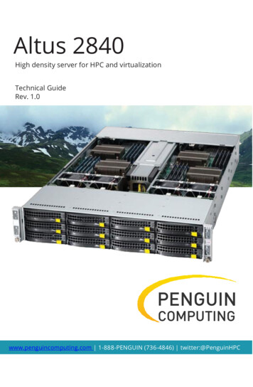
Altus 2840High density server for HPC and virtualizationTechnical GuideRev. 1.0PENGUINCOMPUTINGwww.penguincomputing.com 1-888-PENGUIN (736-4846) twitter:@PenguinHPC
SUPER A SERVER 2022TG-HTRFA SERVER 2022TG-HIBQRFUSER’S MANUALRevision 1.0
The information in this User’s Manual has been carefully reviewed and is believed to be accurate.The vendor assumes no responsibility for any inaccuracies that may be contained in this document,makes no commitment to update or to keep current the information in this manual, or to notify anyperson or organization of the updates. Please Note: For the most up-to-date version of thismanual, please see our web site at www.supermicro.com.Super Micro Computer, Inc. ("Supermicro") reserves the right to make changes to the productdescribed in this manual at any time and without notice. This product, including software anddocumentation, is the property of Supermicro and/or its licensors, and is supplied only under alicense. Any use or reproduction of this product is not allowed, except as expressly permitted bythe terms of said license.IN NO EVENT WILL SUPERMICRO BE LIABLE FOR DIRECT, INDIRECT, SPECIAL, INCIDENTAL,SPECULATIVE OR CONSEQUENTIAL DAMAGES ARISING FROM THE USE OR INABILITY TOUSE THIS PRODUCT OR DOCUMENTATION, EVEN IF ADVISED OF THE POSSIBILITY OFSUCH DAMAGES. IN PARTICULAR, SUPERMICRO SHALL NOT HAVE LIABILITY FOR ANYHARDWARE, SOFTWARE, OR DATA STORED OR USED WITH THE PRODUCT, INCLUDING THECOSTS OF REPAIRING, REPLACING, INTEGRATING, INSTALLING OR RECOVERING SUCHHARDWARE, SOFTWARE, OR DATA.Any disputes arising between manufacturer and customer shall be governed by the laws of SantaClara County in the State of California, USA. The State of California, County of Santa Clara shallbe the exclusive venue for the resolution of any such disputes. Super Micro's total liability for allclaims will not exceed the price paid for the hardware product.FCC Statement: This equipment has been tested and found to comply with the limits for a ClassA digital device pursuant to Part 15 of the FCC Rules. These limits are designed toprovide reasonable protection against harmful interference when the equipment is operated in acommercial environment. This equipment generates, uses, and can radiate radio frequencyenergy and, if not installed and used in accordance with the manufacturer’s instruction manual,may cause harmful interference with radio communications. Operation of this equipment in aresidential area is likely to cause harmful interference, in which case you will be required to correctthe interference at your own expense.California Best Management Practices Regulations for Perchlorate Materials: This Perchloratewarning applies only to products containing CR (Manganese Dioxide) Lithium coin cells. “PerchlorateMaterial-special handling may apply. See NG: Handling of lead solder materials used in thisproduct may expose you to lead, a chemical known tothe State of California to cause birth defects and otherreproductive harm.Manual Revision 1.0Release Date: December 30, 2010Unless you request and receive written permission from Super Micro Computer, Inc., you may notcopy any part of this document.Information in this document is subject to change without notice. Other products and companiesreferred to herein are trademarks or registered trademarks of their respective companies or markholders.Copyright 2010 by Super Micro Computer, Inc.All rights reserved.Printed in the United States of America
PrefacePrefaceAbout This ManualThis manual is written for professional system integrators and PC nanduseoftheA SERVER 2022TG-HTRF/HIBQRF. Installation and maintainance should beperformed by experienced technicians only.The A SERVER 2022TG-HTRF/HIBQRF is a high-end server based on theSC827H-R1400BP 2U rackmount chassis and the H8DGT-HF/HIBQF dual processorserverboard. The only difference between the 2022TG-HTRF and 2022TG-HIBQFservers is that the 2022TG-HIBQF server has a QSFP Infi niBand Connector andthe the 2022TG-HTRF does not.Manual OrganizationChapter 1: IntroductionThe fi rst chapter provides a checklist of the main components included withtheserver system anddescribes themain featuresoftheH8DGT-HF/HIBQF serverboard and the SC827H-R1400BP chassis.Chapter 2: Server InstallationThis chapter describes the steps necessary to install the A SERVER2022TG-HTRF/HIBQRF into a rack and check out the server confi guration prior topowering up the system. If your server was ordered without processor and memorycomponents, this chapter will refer you to the appropriate sections of the manualfor their installation.Chapter 3: System InterfaceRefer here for details on the system interface, which includes the functionsand information provided by the control panel on the chassis as well as otherLEDs located throughout the system.Chapter 4: System SafetyYou should thoroughly familiarize yourself with this chapter for a general overviewof safety precautions that should be followed when installing and servicing the A SERVER 2022TG-HTRF/HIBQRF.iii
A SERVER 2022TG-HTRF/HIBQRF User's ManualChapter 5: Advanced Serverboard SetupChapter 5 provides detailed information on the H8DGT-HF/HIBQF serverboard,including the locations and functions of connections, headers and jumpers. Referto this chapter when adding or removing processors or main memory andwhen reconfi guring the serverboard.Chapter 6: Advanced Chassis SetupRefer to Chapter 6 for detailed information on the SC827H-R1400BP server chassis.You should follow the procedures given in this chapter when installing, removing orreconfi guring SATA or peripheral drives and when replacing system power supplyunits and cooling fans.Chapter 7: BIOSThe BIOS chapter includes an introduction to BIOS and provides detailedinformation on running the CMOS Setup Utility.Appendix A: BIOS Error Beep CodesAppendix B: System Specifi cationsiv
A SERVER 2022TG-HTRF/HIBQRF User's ManualTable of ContentsChapter 1 Introduction123OverviewServerboard Features1-11-2Processors1-2Memory1-2Serial ATA1-2PCI Expansion Slots1-2Onboard Controllers/Ports1-2Graphics Controller1-3Infi niBand1-3Other Features1-3Server Chassis Features1-3System Power1-3SATA Subsystem1-3Front Control Panel1-4I/O Backplane1-4Cooling System1-4Air Shrouds1-4Mounting Rails1-44Contacting Supermicro1-61-52U Twin2: System Notes1-7Nodes1-7System Power1-7SATA Backplane/Drives1-7Chapter 2 Server Installation2-1Overview2-12-2Unpacking the System2-12-3Preparing for Setup2-1Choosing a Setup Location2-1Warnings and Precautions!2-2Rack Precautions2-2Server Precautions2-2Rack Mounting Considerations2-3Ambient Operating Temperature2-3Reduced Airfl ow2-3Mechanical Loading2-3v
Table of ContentsCircuit Overloading2-3Reliable Ground42-3Installing the System into a Rack2-4Separating the Sections of the Rack Rails2-4Installing the Inner Rail Extension2-5Outer Rack Rails2-65Checking the Serverboard Setup2-62-8Checking the Drive Bay Setup2-10Chapter 3 System Interface3-1Overview3-14-2Control Panel Button3-24-3Control Panel LEDs3-24-4Drive Carrier LEDs3-3SATA Drives3-3SCSI Drives3-3Chapter 4 System Safety4-1Electrical Safety Precautions4-14-2General Safety Precautions4-24-3ESD Precautions4-34-4Operating Precautions4-3Chapter 5 Advanced Serverboard Setup123Handling the d InstallationConnecting Cables5-25-2Connecting Data Cables5-34I/O Port Connections5-35-5Processor and Heatsink Installation5-4Installing a Passive CPU Heatsink5-6Removing the Heatsink5-6Installing Memory5-7DIMM Module Population Confi guration5-967PCI Expansion Cards5-105-8Serverboard Details5-115-9Connector Defi nitions5-135-10Jumper Settings5-16Explanation of Jumpers5-16vi
A SERVER 2022TG-HTRF/HIBQRF User's Manual5-11Onboard Indicators5-185-12SATA Ports5-195-13Enabling SATA RAID5-20Serial ATA (SATA)5-20Installing the OS/SATA Driver5-20Building a Driver Diskette5-145-20Enabling SATA RAID in the BIOS5-21Using the Adaptec RAID Utility5-22Installing the RAID Driver During OS Installation5-22Installing Drivers5-23Supero Doctor III5-24Chapter 6 Advanced Chassis Setup12Static-Sensitive Devices6-1Precautions6-1Control Panel6-2Unpacking6-23Chassis Cover4Air Guides6-36-46-5Checking the Airfl ow6-4Installation Complete6-46System Fans6-57Optional Fan Confi gurations6-5Removing and Installing the Backplane6-7Removing the Backplane6-7Installing the Backplane896-106-116-9Installing the Motherboard6-10I/O Shield6-10Permanent and Optional Standoffs6-10Adapter Card Replacement6-12Add-on Card/Expansion Slot Setup6-13Drive Bay Installation/Removal6-15Accessing the Drive Bays6-15Power Supply6-19Power Supply Replacement6-19Power Supply Replacement6-19vii
Table of ContentsChapter 7 BIOS1Introduction7-1Starting BIOS Setup Utility7-1How To Change the Confi guration Data7-1Starting the Setup Utility7-22Main Setup7-27-3Advanced Setup Confi gurations7-44-3Security Menu7-164Boot Menu7-165Exit Menu7-17Appendix A BIOS Error Beep CodesAppendix B Installing WindowsB-1Installing the Windows OS for a RAID System . B-1B-2Installing the Windows OS for a Non-RAID System. B-2Appendix C System Specifi cationsviii
Chapter 1: IntroductionChapter 1Introduction1OverviewThe A SERVER 2022TG-HTRF/HIBQRF is a high-end server comprised of two mainsubsystems: the SC827H-R1400BP 2U server chassis and the H8DGT-HF/HIBQFdual processor serverboard. Please refer to our web site for information on operatingsystems that have been certifi ed for use with the system (www.supermicro.com).In addition to the serverboard and chassis, various hardware componentshave been included with the 2022TG-HTRF/HIBQRF, as listed below:Four (4) Air shrouds for H8 DP (G34), SC827 chassis (MCP-310-82711-0B)Four (4) 4-port Adapter cards for backplane (BPN-ADP-4SATA-H8)One (1) SAS/SATA Backpane (BPN-SAS-827B)Eight (8) 1U Passive CPU heatsinks for AMD Socket G34 (SNK-P0042P)Four (4) Riser Cards (RSC-R1U-E16R)Twelve (12) Hard Disk Drive Trays (MCP-220-00075-0B)One (1) Rack mount rail kit (MCP-290-00053-0N)Four (4) 80x38mm 4-pin PWM chassis fans (FAN-0111L4)One CD containing manual, drivers and utilities1-1
A SERVER 2022TG-HTRF/HIBQRF User's Manual1-2Serverboard FeaturesAt the heart of the A SERVER 2022TG-HTRF/HIBQRF lies the H8DGT-HF/HIBQF,a dual processor serverboard based on the AMD SR5670/SP5100 Chipsetand designed to provide maximum performance. Up to four of these serverboardscan be mounted in the SC827 chassis.The sections below cover the main features of the H8DGT-HF/HIBQF serverboard(see Figure 1-1 for a block diagram of the chipset).ProcessorsThe H8DGT-HF/HIBQF supports single or dual AMD Opteron 6100 series processors(Socket G34 type). Please refer to the serverboard description pages on our website for a complete listing of supported processors (www.supermicro.com).MemoryThe H8DGT-HF/HIBQF has sixteen (16) single/dual/tri/quad channel DIMM slotssupporting up to 256 GB of DDR3-1333/1066/800 registered ECC or 64GB of DDR3Unbuffered ECC/non-ECC SDRAM. See Chapter 5 for details.Serial ATAA Serial ATA controller is integrated into the AMD SP5100 Chipset to provide afour-port 3 Gb/s SATA subsystem, which is RAID 0 and 1 supported. The SATAdrives are hot-swappable units.Note: The operating system you use must have RAID support to enable the hotswap capability and RAID function of the SATA drives.PCI Expansion SlotsThe H8DGT-HF/HIBQF has one PCI Express 2.0 x16 expansion slot.Onboard Controllers/PortsOne Fast UART 16550 compatible serial port and a Mellonox Connect-X Infi niBand(on 2022TG-HIBQRF server only) supporting a single QSFP connector are locatedon the serverboard. The color-coded I/O ports include one COM port (an additionalCOM header is located on the serverboard), a VGA (monitor) port, two USB 2.0ports (additional two internal USB headers and a USB Type A port are includedon the serverboard), an IPMI dedicated LAN port and two gigabit Ethernet ports.1-2
Chapter 1: IntroductionGraphics ControllerThe H8DGT-HF/HIBQF features an integrated Matrox G200 graphics controllerwith 16 MB DDR2 memory.Infi niBandThe 2022TG-HIBQRF includes a QDR (quad data rate) speed InfiniBandQSFP connector. Infi niBand is a scalable serial communications link intended forconnecting processors with high-speed peripherals.Other FeaturesOther onboard features that promote system health include onboard voltagemonitors, a chassis intrusion header, auto-switching voltage regulators, chassis andCPU overheat sensors, virus protection and BIOS rescue.1-3Server Chassis FeaturesThe following is a general outline of the main features of the SC827server chassis.System PowerEach SC827 chassis model includes a high-effi ciency 80 Plus Gold certifi ed powersupply, rated at 1400 Watts plus one redundant backup power supply. In the unlikelyevent your power supply fails, replacement is simple and can be accomplishedwithout tools.SATA SubsystemThe SC827 supports up to twelve 3.5" hot-swap SATA drives in trays (3 for eachnode). These drives are hot-swappable units and are connected to abackplane that provides power and control.Note: The operating system you use must have RAID support to enable the hotswap capability of the drives.1-3
A SERVER 2022TG-HTRF/HIBQRF User's ManualFront Control PanelSC827 models include four front panels on the handles of the chassis which controleach of the systems. Each control panel on the A SERVER 2022TGHTRF/HIBQRF provides you with system monitoring and control for one servernode. LEDs indicate system power, HDD activity, network activity, systemoverheat and power supply failure. A main power button and a system resetbutton are also included.I/O BackplaneThe SC827 is an ATX form factor chassis designed to be used in a 2U rackmountconfi guration. The SAS827B I/O backplane provides a low-profi le add-oncard slot, a COM port, a VGA port, two USB 2.0 ports and two gigabit Ethernetports per node.For more information regarding the backplane, view the appendices found at theend of this manual.Cooling SystemThe SC827 chassis accepts four system fans powered from either backpane or theserverboards. If not powered from the backpane, the SC827B model chassis powerstwo fans from two motherboards, so that when one of the motherboard drawers isremoved, the second motherboard will continue running both fans.Air ShroudsThe SC827 chassis includes four mylar air shrouds that direct the airfl ow wherecooling is needed on each serverboard. Always use the air shroud included withyour chassis on each serverboard.Mounting RailsThe SC827 includes a set of quick-release rails, and can be placed in a rack forsecure storage and use. To setup your rack, follow the step-by-step instructionsincluded in this manual.1-4
Chapter 1: IntroductionFigure 1-1. AMD SR5670/SP5100 Chipset:System Block DiagramNote: This is a general block diagram. Please see Chapter 5 for details.DIMM A1DIMM A0DIMM B1DIMM B0DIMM C1DIMM C0DIMM A1DIMM A0DIMM B1DIMM B0DIMM C1DIMM C0DIMM D1DIMM D0HT3 Link8x8-3.2GT/sAMDSocket G34CPU2DIMM D1DIMM D0HT3 Link8x8-3.2GT/sAMDSocket G34CPU1HT3 Link(8 8)x(8 8)-6.4GT/sHT3 Link16x16-5.2GT/sPCI-E GEN2 X16Slot1RJ45INTELKAWELARJ45PCI-E GEN2 X4SR5670PCI-E GEN2 X8MellanoxConnectX(H8DGT-HIBQF)RMIIA-LinkVGAPSU I2CClock GenPCIDDR2 SDRAM64Mb X16bitMUXBMCVGAWPCM450-RSMBusSP5100SATA x6LPCIPMBCOM1COM2HWMSIOW83795G W83527SPI FlashFE PHYRTL8201NRJ45 USB x51-5
A SERVER 2022TG-HTRF/HIBQRF User's Manual1-4Contacting SupermicroHeadquartersAddress:Super Micro Computer, Inc.980 Rock Ave.San Jose, CA 95131 U.S.A.Tel:Fax:Email:Web Site: 1 (408) 503-8000 1 (408) 503-8008marketing@supermicro.com (General Information)support@supermicro.com (Technical Support)www.supermicro.comEuropeAddress:Super Micro Computer B.V.Het Sterrenbeeld 28, 5215 ML's-Hertogenbosch, The NetherlandsTel:Fax:Email: 31 (0) 73-6400390 31 (0) 73-6416525sales@supermicro.nl (General Information)support@supermicro.nl (Technical Support)rma@supermicro.nl (Customer Support)Asia-PacificAddress:Super Micro Computer, Inc.4F, No. 232-1, Liancheng Rd.Chung-Ho 235, Taipei CountyTel:Fax:Web Site:Taiwan, R.O.C. 886-(2) 8226-3990 886-(2) 8226-3991www.supermicro.com.twTechnical 228-1366, ext.132 or 1391-6
Chapter 1: Introduction1-52U Twin2: System NotesAs a 2U Twin2 confi guration, the 2022TG-HTRF/HIBQRF is a unique server system.With four system boards incorporated into a single chassis acting as four separatenodes, there are several points you should keep in mind.NodesEach of the four serverboards act as a separate node in the system. Asindependant nodes, each may be powered off and on without affecting theothers. In addition, each node is a hot-swappable unit that may be removed fromthe rear of the chassis. The nodes are connected to the server backplane bymeans of an adapter card.Note: A guide pin is located between the upper and lower nodes on the innerchassis wall. This guide pin also acts as a “stop” when a node is fully installed. Iftoo much force is used when inserting a node this pin may break off. Take care toslowly slide a node in until you hear the “click” of the locking tab seating itself.System PowerA single 1400W power supply is used to provide the power for all four serverboards.Each serverboard however, can be shut down independently of the other with thepower button on its own control panel. As an option, you may add an additional1400W power supply module for power redundancy.SATA Backplane/DrivesAs a system, the 2022TG-HTRF/HIBQRF supports the use of twelve SATA drives.A single SATA backplane works to apply system-based control for power and fanspeed functions, yet at the same time logically connects a set of three SATA drivesto each serverboard. Consequently, RAID setup is limited to a three-drive scheme(RAID cannot be spread across all twelve drives). See the Drive Bay Installation/Removal section in Chapter 6 for the logical hard drive and node confi guration.1-7
A SERVER 2022TG-HTRF/HIBQRF User's ManualNotes1-8
Chapter 2: Server InstallationChapter 2Server pchecklisttogetyourA SERVER 2022TG-HTRF/HIBQRF up and running. Following these steps in theorder given should enable you to have the system operational within a minimumamount of time. This quick setup assumes that your system has come to you withthe processors and memory preinstalled. If your system is not already fullyintegrated with a serverboard, processors, system memory etc., please turn to thechapter or section noted in each step for details on installing specifi c components.2Unpacking the SystemYou should inspect the box the A SERVER 2022TG-HTRF/HIBQRF was shippedin and note if it was damaged in any way. If the server itself shows damage youshould fi le a damage claim with the carrier who delivered it.Decide on a suitable location for the rack unit that will hold the A SERVER 2022TG-HTRF/HIBQRF. It should be situated in a clean, dust-free ricalnoiseandelectromagnetic fi elds are generated. You will also need it placed near agrounded power outlet. Read the Rack and Server Precautions in the nextsection.3Preparing for SetupThe box the A SERVER 2022TG-HTRF/HIBQRF was shipped in should includetwo sets of rail assemblies, two rail mounting brackets and the mounting screwsyou will need to install the system into the rack. Follow the steps in the ordergiven to complete the installation process in a minimum amount of time. Pleaseread this section in its entirety before you begin the installation procedure outlinedin the sections that follow.Choosing a Setup LocationLeave enough clearance in front of the rack to enable you to open the frontdoor completely ( 25 inches) and approximately 30 inches of clearance in theback of
Super Micro Computer, Inc. ("Supermicro") reserves the right to make changes to the product described in this manual at any time and without notice. This product, including software and documentation, is the property of Supermicro an