Transcription
Cisco Catalyst 9500 Series SwitchesFIPS 140-2 Non-Proprietary Security PolicyLevel 1 ValidationVersion 1.2March 10th, 2021
Contents1INTRODUCTION . 31.11.21.31.41.52PURPOSE . 3THE CRYPTOGRAPHIC MODULES VALIDATION LEVEL. 3REFERENCES . 4TERMINOLOGY . 4DOCUMENT ORGANIZATION . 4CISCO SYSTEMS CATALYST 9500 SERIES SWITCHES. 52.1 CRYPTOGRAPHIC MODULES PHYSICAL CHARACTERISTICS . 62.2 MODULES INTERFACES . 72.3 ROLES, SERVICES AND AUTHENTICATION . 72.3.1 User Role . 82.3.2 Crypto-Officer Role . 82.3.3 Unauthorized Role . 102.3.4 Services Available in Non-FIPS Mode of Operation . 102.4 CRYPTOGRAPHIC ALGORITHMS . 112.5 CRYPTOGRAPHIC KEY/CSP MANAGEMENT . 132.6 SELF-TESTS . 172.6.1 Power-On Self-Tests (POSTs) . 172.6.2 Conditional Tests. 182.7 PHYSICAL SECURITY. 193SECURE OPERATION . 193.13.2SYSTEM INITIALIZATION AND CONFIGURATION . 19VERIFY FIPS CONFIGURATION . 20
1 Introduction1.1 PurposeThis document is the non-proprietary Cryptographic Module Security Policy for the Cisco Catalyst 9500 Series Switches runningIOS-XE Firmware Versions 16.9.2 or 16.12. This security policy describes how the modules listed below meet the securityrequirements of FIPS 140-2 level 1, and how to operate the switches with on-board crypto enabled in a secure FIPS 140-2 mode.The Cisco Catalyst 9500 Series has eight primary SKUs that are covered in this validation effort as listed below:Cisco Catalyst C9500-32CCisco Catalyst C9500-32QCCisco Catalyst C9500-48YCCisco Catalyst C9500-24YCCisco Catalyst C9500-24QCisco Catalyst C9500-12QCisco Catalyst C9500-40XCisco Catalyst C9500-16XIncluding optional network modules listed below:C9500-NM-8XC9500-NM-2QFIPS 140-2 (Federal Information Processing Standards Publication 140-2 — Security Requirements for Cryptographic Modules)details the U.S. Government requirements for cryptographic modules. More information about the FIPS 140-2 standard andvalidation program is available on the NIST website at e-Validation-Program.1.2 The Cryptographic Modules Validation LevelThe following table lists the level of validation for each area in the FIPS PUB 140-2.Table 1- The Cryptographic Modules Validation LevelNo.Area TitleLevel1Cryptographic Module Specification12Cryptographic Module Ports and Interfaces13Roles, Services, and Authentication34Finite State Model15Physical Security16Operational EnvironmentN/A7Cryptographic Key management18Electromagnetic Interface/Electromagnetic Compatibility19Self-Tests110Design Assurance211Mitigation of Other AttacksN/AOverall module validation level1
1.3 ReferencesThis document deals only with operations and capabilities of the modules in the technical terms of a FIPS 140-2 cryptographicmodule security policy. More information is available on the switches from the following sources:The Cisco Systems website contains information on the full line of Cisco products. Please refer to the following websites for CiscoCatalyst 9500 Series Switches /catalyst-9500-series-switches/index.htmlFor answers to technical or sales related questions, please refer to the contacts listed on the Cisco Systems website atwww.cisco.com.The NIST Validated Modules website tml) contains contact information foranswers to technical or sales-related questions for the modules.1.4 TerminologyIn this document, the Cisco Catalyst 9500 Series Switches is referred to as the switches, the cryptographic modules, or themodules.1.5 Document OrganizationThe Security Policy document is part of the FIPS 140-2 Submission Package. In addition to this document, the Submission Packagecontains:Vendor Evidence documentFinite State MachineOther supporting documentation as additional referencesThis document provides an overview of the Cisco Catalyst 9500 Series Switches and explains the secure configuration andoperation of the modules. This introduction section is followed by Section 2, which details the general features and functionalityof the switches. Section 3 specifically addresses the required configuration for the FIPS-mode of operation.With the exception of this Non-Proprietary Security Policy, the FIPS 140-2 Validation Submission Documentation is Ciscoproprietary and is releasable only under appropriate non-disclosure agreements. For access to these documents, please contactCisco Systems.
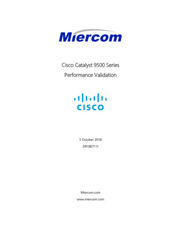
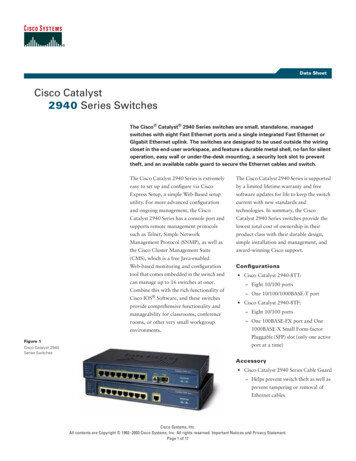
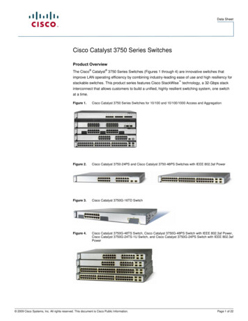
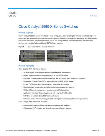
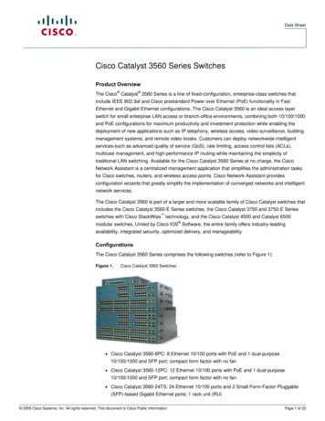
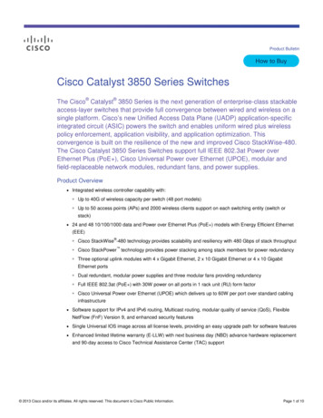
2Cisco Systems Catalyst 9500 Series SwitchesThe Cisco Catalyst 9500 Series Switches are the next generation of enterprise-class core and aggregation layer switches,supporting full programmability and serviceability. The series is Cisco’s lead purpose-built fixed core and aggregation enterpriseswitching platform, built for security, IoT, and cloud. The switches also include non-blocking 40 and 100 Gigabit Ethernet QuadSmall Form-Factor Pluggable (QSFP , QSFP28) and 1-, 10-, and 25-Gigabit Ethernet Small Form-Factor Pluggable Plus(SFP/SFP /SFP28) switches with granular port densities that fit diverse campus needs.The cryptographic modules support advanced routing and infrastructure services (such as Multiprotocol Label Switching [MPLS]Layer 2 and Layer 3 VPNs, Multicast VPN [MVPN], and Network Address Translation [NAT]); Cisco Software-Defined Accesscapabilities (such as a host tracking database, cross-domain connectivity, and VPN Routing and Forwarding [VRF]-awareLocator/ID Separation Protocol [LISP]); and Cisco StackWise virtual technology that are critical for their placement in the campuscore.The illustration below shows a representation of Catalyst 9500 switches. All the switch models have similar appearances, Internalcapability and port numbers make differences in the models.Figure 1: Cisco Catalyst 9500 Series SwitchesCisco Unified Access Data Plane (UADP) Application-Specific Integrated Circuit (ASIC) offers configurable allocation of Layer 2and Layer 3 forwarding, Access Control Lists (ACLs), and Quality-of-Service (QoS) entries. The Cisco Catalyst 9500 Series Switchessupport optional network modules for uplink ports on some of the configurations. The default switch configuration does notinclude the network modules.(a) 8-port 1/10 Gigabit Ethernet with SFP/SFP (b) 2-port 40 Gigabit Ethernet with QSFP Figure 2: Network Modules (a) C9500-NM-8X and (b) C9500-NM-2QThe cryptographic modules have two mode of operations: FIPS mode and non-FIPS mode. Non-FIPS mode is default for theswitches. It is the Crypto-Officer’s responsibility to install and configure the modules in FIPS mode of operation. Detailedinstructions to setup FIPS mode of operation can be found in Secure Operation section of this document.
Note: Cisco StackWise virtual technology on Catalyst 9500 Series Switches is disabled in FIPS mode of operation and was nottested for FIPS 140-2 requirements.2.1 Cryptographic Modules Physical CharacteristicsThe modules are tested and validated for FIPS140-2 security level 1 as multiple-chip standalone cryptographic modules. Thecryptographic boundary of the switches is defined as encompassing the “top,” “front,” “left,” “right,” ”rear,” and “bottom”surfaces of the chassis for the switches and the casing for the switches. Included in the physical boundary is the ACT2LiteCryptographic Module (CMVP Certificate #3637). All switches ship with the 650W/950W/1600W AC power supply as default andhas built-in fans. The table below shows the models tested as part of FIPS 140-2 validation:Table 2: Cisco Catalyst 9500 Series Switches with Port Density100G Port40G Port25G Port10G Port1G PortModel and 48*-12-C9500-32C: 32-port 100 Gigabit Ethernet switch with QSFP28C9500-32QC: 32-port 40 Gigabit Ethernet switch with QSFP C9500-48YC: 48-port 1/10/25G Gigabit Ethernet switch with SFP28C9500-24YC: 24-port 1/10/25G Gigabit Ethernet switch with SFP28C9500-24Q: 24-port 40 Gigabit Ethernet switch with QSFP C9500-12Q: 12-port 40 Gigabit Ethernet switch with QSFP
100G Port40G Port25G Port10G Port1G PortModel and Description4848/8*-2-2424/8*-2-C9500-40X: 40-port 1/10 Gigabit Ethernet switch with SFP/SFP Support for optional network modules (C9500-NM-8X or C9500-NM-2Q) for uplink portsC9500-16X: 6-port 1/10 Gigabit Ethernet switch with SFP/SFP Support for optional network modules (C9500-NM-8X or C9500-NM-2Q) for uplink ports* Gigabit Ethernet port with breakout cable2.2 Modules InterfacesThe modules provide a number of physical and logical interfaces to the device, and the physical interfaces provided by themodules are mapped to the following FIPS 140-2 defined logical interfaces: data input, data output, control input, status output,and power. The logical interfaces and their mapping are described in the following Table 3.Table 3: Catalyst 9500 Physical Interface/Logical Interface MappingFIPS 140-2 Logical InterfacePhysical Interfaces and CablingData Input Interface, Data Output InterfaceGigabit Ethernet port: SFP, SFP , SFP28, QSFP , QSFP28Control Input Interface, Status Output InterfaceGigabit Ethernet port: SFP, SFP , SFP28, QSFP , QSFP28Ethernet management port: RJ-45 connectorsManagement console port: RJ-45-to-DB9 cable for PC connectionsPower switchStatus Output InterfaceLight Emitting Diode (LED)Power InterfaceAC power connectorThe following physical interfaces are prohibited from usage in FIPS mode of operation: Universal Serial Bus (USB) 3.0SATA SSD StorageWireless Console Access with Bluetooth2.3 Roles, Services and AuthenticationThe modules support identity-based authentication. Each user is authenticated upon initial access to the modules. There are tworoles in the switches that may be assumed: Crypto-Officer (CO) role and the User role. The administrator of the switches assumesthe CO role in order to configure and maintain the switches. The Users are the processes that exercise security services over thenetwork.
2.3.1 User RoleThe role is assumed by users obtaining secured data services. From a logical view, user activity exists in the data-plane via definedData Input/ Output Interfaces. Users are authenticated using EAP methods and 802.1X-REV, and their data is protected with802.1AE protocols. EAP and 802.1X-REV can use password-based credentials for User role authentication – in such a case the userpasswords must be at least eight (8) characters long. The password must contain at least one special character and at least onenumber character along with six additional characters taken from the 26-upper case, 26-lower case, 10-numbers and 32-specialcharacters (procedurally enforced). This requirement gives (26 26 10 32 ) 94 options of character to choose from. Withoutrepetition of characters, the number of probable combinations is the combined probability from 6 characters(94x93x92x91x90x89) times one special character (32) times 1 number (10), which turns out to be (94x93x92x91x90x89x32x10 ) 187,595,543,116,800.Therefore, the associated probability of a successful random attempt is approximately 1 in187,595,543,116,800, which is less than 1 in 1,000,000 required by FIPS 140-2. In order to successfully guess the sequence in oneminute would require the ability to make over 3,126,592,385,280 guesses per second, which far exceeds the operationalcapabilities of the switches.EAP and 802.1X-REV can also authenticate the User role via certificate credentials by using 2048-bit RSA keys – in such a case thesecurity strength is 112 bits, so the associated probability of a successful random attempt is 1 in 2 112, which is less than 1 in1,000,000 required by FIPS 140-2. To exceed a one in 100,000 probability of a successful random key guess in one minute, anattacker would have to be capable of approximately 8.65x1031 attempts per second, which far exceeds the operationalcapabilities of the modules.The services available to the User role accessing the CSPs, the type of access – read (r), write (w), execute (e) and zeroized/delete(d) – and which role accesses the CSPs are listed below:Table 4 - User ServicesServicesDescriptionKeys and CSPs AccessSecured DataplaneMACsec Network Functions: authentication, accesscontrol, confidentiality and data integrity servicesprovided by the MACsec protocolDiffie- Hellman (DH) private key, Diffie-Hellman (DH)public key, Diffie- Hellman (DH) Shared Secret,MACsec Security Association Key (SAK), MACsecConnectivity Association Key (CAK), MACsec KeyEncryption Key (KEK), MACsec Integrity Check Key(ICK), Pairwise Master Key (PMK), Protected AccessCredential (PAC) Key, Pairwise Transient Key (PTK),Key Confirmation Key (KCK) (w, e, d)Bypass ServicesTraffic without cryptographic processing exceptauthentication. The rule must have been previouslyconfigured by the Crypto-Officer.Diffie- Hellman (DH) private key, Diffie-Hellman (DH)public key, Diffie- Hellman (DH) Shared Secret (w, e,d)2.3.2 Crypto-Officer RoleThis role is assumed by an authorized CO connecting to the switches via CLI through the console port and performing managementfunctions and modules configuration. Additionally, the stack master is considered CO for stack members. From a logical view, COactivity exists only in the control plane. IOS prompts the CO for their username and password, and, if the password is validatedagainst the CO’s password in IOS memory, the CO is allowed entry to the IOS executive program. A CO can assign permission toaccess the CO role to additional accounts, thereby creating additional COs. The modules support RADSec for authentication ofCOs.CO passwords must be at a minimum eight (8) characters long. The Secure Operation sections procedurally enforces thepassword must contain at least one special character and at least one number character along with six additional characters takenfrom the 26-upper case, 26-lower case, 10-numbers and 32-special characters (procedurally enforced). This requirement gives
(26 26 10 32 ) 94 options of character to choose from. Without repetition of characters, the number of probablecombinations is the combined probability from 6 characters (94x93x92x91x90x89) times one special character (32) times 1number (10), which turns out to be (94x93x92x91x90x89x32x10 ) 187,595,543,116,800. Therefore, the associated probabilityof a successful random attempt is approximately 1 in 187,595,543,116,800, which is less than 1 in 1,000,000 required by FIPS140-2. In order to successfully guess the sequence in one minute would require the ability to make over 3,126,592,385,280guesses per second, which far exceeds the operational capabilities of the modules.The Crypto-Officer role is responsible for the configuration of the switches. The services available to the Crypto-Officer roleaccessing the CSPs, the type of access – read (r), write (w), execute (e) and zeroized/delete (d) – and which role accesses the CSPsare listed below:Table 5 – Crypto-Officer ServicesServicesDefine Rules and FiltersDescriptionDefine network interfaces and settings, create commandaliases, set the protocols the switch will support, enableinterfaces and network services, set system date and time,and load authentication information.Keys and CSPs AccessEnable password (r, w, e, d)Log off users, shutdown or reload the switch, manually backup switch configurations, view complete configurations,manage user rights, and restore switch configurations.Create packet Filters that are applied to User data streams oneach interface. Each Filter consists of a set of Rules, whichdefine a set of packets to permit or deny based oncharacteristics such as protocol ID, addresses, ports, TCPconnection establishment, or packet direction.View Status FunctionsView the switch configuration, routing tables, active sessions,health, temperature, memory status, voltage, packetstatistics, review accounting logs, and view physical interfacestatus.Enable password (r, w, e, d)Configure Encryption/BypassSet up the configuration tables for IP tunneling. Set preshared keys and algorithms to be used for each IP range orallow plaintext packets to be set from specified IP address.[IKE session encrypt key, IKE sessionauthentication key, ISAKMP preshared, IKE authentication privateKey, IKE authentication public key,skeyid, skeyid d, SKEYSEED, IPsecencryption key, IPsec authenticationkey] (w, d) and Enable password (r)Configure RemoteAuthenticationSet up authentication account for users and devices usingRADSec (RADIUS over TLS)RADIUS secret, RADIUS Key wrap key,TLS Server RSA private key, TLS ServerRSA public key, TLS pre-master secret,TLS encryption keys, TLSauthentication keys, DRBG entropyinput, DRBG V, DRBG Key (w, e, d)HTTPsHTTP server over TLS (1.0)TLS Server RSA private key, TLS ServerRSA public key, TLS pre-master secret,TLS encryption keys, TLS
ServicesDescriptionKeys and CSPs Accessauthentication keys, DRBG entropyinput, DRBG V, DRBG Key (w, e, d)SSH v2Configure SSH v2 parameter, provide entry and output ofCSPs.DH private DH public key, DH SharedSecret, SSH RSA private key, SSH RSApublic key, SSH session key, SSHsession authentication key, DRBGentropy input, DRBG V, DRBG Key (w,e, d)SNMPv3Configure SNMPv3 MIB and monitor status[SNMPv3 Password, snmpEngineID](r, w, d), SNMP session key, DRBGentropy input, DRBG V, DRBG Key (w,e, d)IPsec VPNConfigure IPsec VPN parameters, provide entry and output ofCSPs.skeyid, skeyid d, SKEYSEED, IKEsession encrypt key, IKE sessionauthentication key, ISAKMP preshared, IKE authentication privateKey, IKE authentication public key,IPsec encryption key, IPsecauthentication key, DRBG entropyinput, DRBG V, DRBG Key (w, e, d)Self-TestsExecute the FIPS 140 start-up tests on demandN/AUser servicesThe Crypto-Officer has access to all User services.User Password (r, w, e, d)ZeroizationZeroize cryptographic keys/CSPs by running the zeroizationmethods classified in table 7, Zeroization column.All CSPs (d)2.3.3 Unauthorized RoleThe services for someone without an authorized role are: passing traffic through the device, view the status output from themodules’ LED pins, and cycle powe
Figure 1: Cisco Catalyst 9500 Series Switches Cisco Unified Access Data Plane (UADP) Application-Specific Integrated Circuit (ASIC) offers configurable allocation of Layer 2 and Layer 3 forwarding, Access Control Lists (ACLs), and Quality-of-Service (QoS) entries. The Cisco Catalyst 9500 Series Switches