Transcription
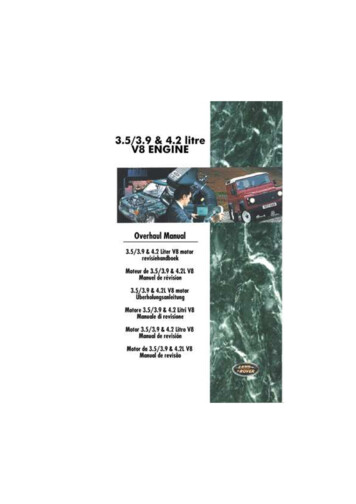
V8ENGINEOVERHAULMANUALThis overhaul manual is applicable to 3.5,3.9 and 4.2 Litre V8 engines with or withoutsuffix B added to the engine serial number.Publication Part No. RCLPublished by Rover Technical Communication 1996 Rover Group Limited
INTRODUCTIONINTRODUCTIONReferencesHow to use this ManualWith the engine and gearbox assembly removed,the crankshaft pulley end of the engine is referred toas the front. References to RH and LH banks ofcylinders is taken viewing from the flywheel end ofthe engine.To assist in the use of this Manual the section title isgiven at the top and the relevant sub-section is givenat the bottom of each page.This manual contains procedures for overhaul of theV8 engine on the bench with the gearbox, clutch,inlet manifold, exhaust manifolds, coolant pump,starter motor, alternator, and all other ancillaryequipment removed. For information regardingGeneral Information, Adjustments, removal of oilseals, engine units and ancillary equipment, consultthe Repair Manual.Operations covered in this Manual do not includereference to testing the vehicle after repair. It isessential that work is inspected and tested aftercompletion and if necessary a road test of thevehicle is carried out particularly where safetyrelated items are concerned.DimensionsEach major section starts with a contents page,listing the information contained in the relevantsub-sections. To assist filing of revised informationeach sub-section is numbered from page 1.The dimensions quoted are to design engineeringspecification with Service limits where applicable.The individual overhaul items are to be followed inthe sequence in which they appear. Items numbersin the illustrations are referred to in the text.Overhaul operations include reference to Servicetool numbers and the associated illustration depictsthe tool. Where usage is not obvious the tool isshown in use. Land Rover tool numbers are quoted,for the equivalent Rover Cars tool number refer tothe Service Tool section. Operations also includereference to wear limits, relevant data, and specialistinformation and useful assembly details.WARNINGS, CAUTIONS and NOTES have thefollowing meanings:WARNING: Procedures which must befollowed precisely to avoid the possibilityof injury.CAUTION: Calls attention to procedureswhich must be followed to avoid damageto components.NOTE: Gives helpful information.INTRODUCTION1
INTRODUCTIONREPAIRS AND REPLACEMENTSSPECIFICATIONWhen replacement parts are required it is essentialthat only Rover recommended parts are used.Rover Group are constantly seeking to improve thespecification, design and production of their vehiclesand alterations take place accordingly. While everyeffort has been made to ensure the accuracy of thisManual, it should not be regarded as an infallibleguide to current specifications of any particularvehicle.Attention is particularly drawn to the following pointsconcerning repairs and the fitting of replacementparts and accessories.Torque wrench setting figures given in this Manualmust be used. Locking devices, where specified,must be fitted. If the efficiency of a locking device isimpaired during removal it must be renewed.The terms of the vehicle warranty may beinvalidated by the fitting of parts other than RoverGroup recommended parts. All Rover Grouprecommended parts have the full backing of thevehicle warranty.Rover Group dealers are obliged to supply onlyRover Group recommended parts.2INTRODUCTIONThis Manual does not constitute an offer for sale ofany particular component or vehicle. Rover Groupdealers are not agents of Rover Group and have noauthority to bind the manufacturer by any expressedor implied undertaking or representation.
INFORMATIONDATAFiring order . . . . . . . . . . . . . . . . . . . . . . . . . . . . . . . 1, 8, 4, 3, 6, 5, 7, 2Cylinders 1, 3, 5, 7 - LH side of engineCylinders 2, 4, 6, 8 - RH side of engineValve springsFree length . . . . . . . . . . . . . . . . . . . . . . . . . . . . . . . . 48.30 mmFitted length . . . . . . . . . . . . . . . . . . . . . . . . . . . . . . . . 40.40 mmLoad at fitted length . . . . . . . . . . . . . . . . . . . . . . . . . . 339 10 NValvesValve stem diameter:Inlet . . . . . . . . . . . . . . . . . . . . . . . . . . . . . . . . . . . . .Exhaust . . . . . . . . . . . . . . . . . . . . . . . . . . . . . . . . . .Valve head diameter:Inlet . . . . . . . . . . . . . . . . . . . . . . . . . . . . . . . . . . . . .Exhaust . . . . . . . . . . . . . . . . . . . . . . . . . . . . . . . . . .Valve installed height - maximum . . . . . . . . . . . . . . .Valve stem to guide clearance:Inlet . . . . . . . . . . . . . . . . . . . . . . . . . . . . . . . . . . . . .Exhaust . . . . . . . . . . . . . . . . . . . . . . . . . . . . . . . . . .8.664 to 8.679 mm8.651 to 8.666 mm39.75 to 40.00 mm34.226 to 34.480 mm47.63 mm0.025 to 0.066 mm0.038 to 0.078 mmValve guidesValve guide installed height . . . . . . . . . . . . . . . . . . . . 24.13 mmValve seatsValve seat angle . . . . . . . . . . . . . . . . . . . . . . . . . . . . 460 15’Valve seat width . . . . . . . . . . . . . . . . . . . . . . . . . . . . 1.5 to 2.0 mmValve face angle . . . . . . . . . . . . . . . . . . . . . . . . . . . . 45 Oil pumpGear to body minimum clearance . . . . . . . . . . . . . . . 0.05 mmOil pressure relief valveSpring free length . . . . . . . . . . . . . . . . . . . . . . . . . . . 81.28 mmOil pump - Engine No’s with suffix BInner to outer rotor clearance - maximum . . . . . . . . . 0.25 mmRotors to cover plate clearance - maximum . . . . . . . 0.1 mmDrive gear wear step depth - maximum . . . . . . . . . . . 0.15 mmOil pressure relief valve - Engine No’s withsuffix BSpring free length . . . . . . . . . . . . . . . . . . . . . . . . . . . 60.0 mmCamshaftMaximum run-out . . . . . . . . . . . . . . . . . . . . . . . . . . . . 0.05 mmGENERAL DATA1
INFORMATIONPiston ringsRing to groove clearance:Top compression . . . . . . . . . . . . . . . . . . . . . . . . . . .2nd compression . . . . . . . . . . . . . . . . . . . . . . . . . . .Ring fitted gap:Top compression . . . . . . . . . . . . . . . . . . . . . . . . . . .2nd compression . . . . . . . . . . . . . . . . . . . . . . . . . . .Oil control rails . . . . . . . . . . . . . . . . . . . . . . . . . . . . .Oil control ring width . . . . . . . . . . . . . . . . . . . . . . . . .0.05 to 0.10 mm0.05 to 0.10 mm0.44 to 0.57 mm0.44 to 0.57 mm0.38 to 1.40 mm3.00 mm, maximumPistonsClearance in bore, measured at bottom ofskirt at right angles to bore . . . . . . . . . . . . . . . . . . . . 0.018 to 0.033 mmGudgeon pinsLength . . . . . . . . . . . . . . . . . . . . . . . . . . . . . . . . . . . . 72.67 to 72.79 mmDiameter . . . . . . . . . . . . . . . . . . . . . . . . . . . . . . . . . . 22.215 to 22.220 mmClearance in piston . . . . . . . . . . . . . . . . . . . . . . . . . . 0.002 to 0.007 mmConnecting rodsLength between centres . . . . . . . . . . . . . . . . . . . . . . 143.81 to 143.71 mmCylinder boreCylinder bore diameter:3.5 engine . . . . . . . . . . . . . . . . . . . . . . . . . . . . . . . . 88.90 mm3.9 engine . . . . . . . . . . . . . . . . . . . . . . . . . . . . . . . . 94.00 mm4.2 engine . . . . . . . . . . . . . . . . . . . . . . . . . . . . . . . . 94.00 mmCrankshaftMain journal diameter . . . . . . . . . . . . . . . . . . . . . . . .Minimum regrind diameter . . . . . . . . . . . . . . . . . . . .Maximum out of round . . . . . . . . . . . . . . . . . . . . . . .Big-end journal diameter . . . . . . . . . . . . . . . . . . . . . .Minimum regrind diameter . . . . . . . . . . . . . . . . . . . .Maximum out of round . . . . . . . . . . . . . . . . . . . . . . .End-float . . . . . . . . . . . . . . . . . . . . . . . . . . . . . . . . . .58.409 to 54.422 mm57.393 to 57.406 mm0.040 mm50.800 to 50.812 mm49.784 to 49.797 mm0.040 mm0.10 to 0.20 mmMain bearingsMain bearing diametrical clearance . . . . . . . . . . . . . . 0.010 to 0.048 mmUndersizes . . . . . . . . . . . . . . . . . . . . . . . . . . . . . . . . 0.254 mm, 0.508 mmBig-end bearingsBig-end bearing diametrical clearance . . . . . . . . . . . 0.015 to 0.055 mmUndersizes . . . . . . . . . . . . . . . . . . . . . . . . . . . . . . . . 0.254 mm, 0.508 mmEndfloat on journal . . . . . . . . . . . . . . . . . . . . . . . . . . . 0.15 to 0.36 mmFlywheelFlywheel minimum thickness . . . . . . . . . . . . . . . . . . . 39.93 mmDrive plateDrive plate setting height . . . . . . . . . . . . . . . . . . . . . . 8.08 to 8.20 mm2GENERAL DATA
INFORMATIONENGINECrankshaft pulley bolt . . . . . . . . . . . . . . . . . . . . . . . .Timing cover to cylinder block bolts ** . . . . . . . . . . . .Camshaft gear bolt . . . . . . . . . . . . . . . . . . . . . . . . . .Rocker cover bolts . . . . . . . . . . . . . . . . . . . . . . . . . . .Rocker shaft to cylinder head bolts . . . . . . . . . . . . . .Cylinder head bolts: *Outer row . . . . . . . . . . . . . . . . . . . . . . . . . . . . . . . . .Centre row . . . . . . . . . . . . . . . . . . . . . . . . . . . . . . . .Inner row . . . . . . . . . . . . . . . . . . . . . . . . . . . . . . . . .Cylinder head bolts - Engine No’s with suffix B: *Stage 1 . . . . . . . . . . . . . . . . . . . . . . . . . . . . . . . . . .Stage 2 . . . . . . . . . . . . . . . . . . . . . . . . . . . . . . . . . .Stage 3 . . . . . . . . . . . . . . . . . . . . . . . . . . . . . . . . . .Lifting eye to cylinder head bolts . . . . . . . . . . . . . . . .Connecting rod bolts . . . . . . . . . . . . . . . . . . . . . . . . .Main bearing cap bolts *** . . . . . . . . . . . . . . . . . . . . .Rear main bearing cap bolts *** . . . . . . . . . . . . . . . . .Flywheel bolts . . . . . . . . . . . . . . . . . . . . . . . . . . . . . .Drive plate and ring gear assembly bolts . . . . . . . . . .Drive plate adapter bolts . . . . . . . . . . . . . . . . . . . . . .Oil sump drain plug . . . . . . . . . . . . . . . . . . . . . . . . . .Oil sump bolts . . . . . . . . . . . . . . . . . . . . . . . . . . . . . .Oil pressure relief plug . . . . . . . . . . . . . . . . . . . . . . . .Oil pump cover to timing cover . . . . . . . . . . . . . . . . .Oil pump cover plate screws - Engine No’s withsuffix B **** . . . . . . . . . . . . . . . . . . . . . . . . . . . . . . . .Oil strainer bolts . . . . . . . . . . . . . . . . . . . . . . . . . . . . .Distributor clamp bolt . . . . . . . . . . . . . . . . . . . . . . . . .Spark plug . . . . . . . . . . . . . . . . . . . . . . . . . . . . . . . . .Coolant pump/timing cover to cylinder block . . . . . . .**********270 Nm22 Nm50 Nm8 Nm38 Nm60 Nm90 Nm90 Nm20 NmThen 90 Further 90 25 Nm50 Nm70 Nm90 Nm80 Nm40 Nm80 Nm40 Nm23 Nm45 Nm12 Nm4 Nm10 Nm20 Nm15 Nm22 NmLightly oil threads prior to assembly.Coat first three threads with Loctite 242 prior to assembly.Coat threads with lubricant EXP16A (Marston Lubricants) prior to assembly.Coat threads with Loctite 222 prior to assembly.TORQUE WRENCH SETTINGS1
INFORMATIONGENERALFor bolts and nuts not otherwise specified:METRICM5 . . . . . . . . . . . . . . . . . . . . . . . . . . . . . . . . . . . . . .M6 . . . . . . . . . . . . . . . . . . . . . . . . . . . . . . . . . . . . . .M8 . . . . . . . . . . . . . . . . . . . . . . . . . . . . . . . . . . . . . .M10 . . . . . . . . . . . . . . . . . . . . . . . . . . . . . . . . . . . . .M12 . . . . . . . . . . . . . . . . . . . . . . . . . . . . . . . . . . . . .M14 . . . . . . . . . . . . . . . . . . . . . . . . . . . . . . . . . . . . .M16 . . . . . . . . . . . . . . . . . . . . . . . . . . . . . . . . . . . . .4 Nm6 Nm18 Nm35 Nm65 Nm80 Nm130 NmUNC / UNF1/4 . . . . . . . . . . . . . . . . . . . . . . . . . . . . . . . . . . . . . .5/16 . . . . . . . . . . . . . . . . . . . . . . . . . . . . . . . . . . . . .3/8 . . . . . . . . . . . . . . . . . . . . . . . . . . . . . . . . . . . . . .7/16 . . . . . . . . . . . . . . . . . . . . . . . . . . . . . . . . . . . . .1/2 . . . . . . . . . . . . . . . . . . . . . . . . . . . . . . . . . . . . . .5/8 . . . . . . . . . . . . . . . . . . . . . . . . . . . . . . . . . . . . . .8-10 Nm25 Nm40 Nm75 Nm90 Nm135 Nm2TORQUE WRENCH SETTINGS
ENGINEThis page is intentionally left blankDESCRIPTION AND OPERATION1
ENGINE2DESCRIPTION AND OPERATION
ENGINECYLINDER BLOCK 7.18.19.Cylinder blockPiston and gudgeon pinConnecting rodCore plugsCamshaftDipstickCamshaft keyTiming chainCamshaft sprocketSpacerDistributor drive gearDistributorOil pump gears *Timing cover and gasket *Timing cover oil seal *Crankshaft pulleyCrankshaft sprocketWoodruff 2.33.34.35.36.37.Centre main bearing shell - upperCrankshaft rear oil sealRear main bearing cap and side sealsConnecting rod capMain bearing capsOil pump cover *Oil pressure relief valve assembly *Oil pressure switch *Oil pump suction pipe and strainerSumpDrain plugTiming cover **Timing cover gasket **Timing cover oil seal **Oil filter **Oil pressure switch **Oil pressure relief valve assembly **Camshaft thrust plate - if fitted* Engine numbers without suffix B** Engine numbers with suffix BDESCRIPTION AND OPERATION3
ENGINECYLINDER HEAD COMPONENTS1.2.3.4.5.6.7.8.9.10.4Cylinder headRocker coverPCV filterRocker shaftTappetPushrodRocker shaft bracketRocker armRocker shaft springPCV air intake filterDESCRIPTION AND OPERATION11.12.13.14.15.16.17.18.Engine oil filler capInlet valve seal, spring, cap, and colletsExhaust valve seal, spring, cap and colletsInlet valve and seatExhaust valve and seatInlet manifold gasket and sealsCylinder head gasketValve guide
ENGINEOperationThe V8 engine is an eight cylinder, water cooled unitcomprising of cast aluminium cylinder block andcylinder heads.The two banks of steel cylinder liners which arepressed down to stops in the cylinder block, are setat 900 to each other. The crankshaft is carried in fivemain bearings, end-float being controlled by thethrust faces of the upper centre main bearing shell.The centrally located camshaft is driven by thecrankshaft via an inverted tooth chain. The valvesare operated by rockers, pushrods and hydraulictappets. Distributor drive is by skew gear from thefront of the camshaft.The aluminium alloy, pistons have two compressionrings and an oil control ring and are secured to theconnecting rods by semi-floating gudgeon pins. Onlater 4.2L engines the gudgeon pin is offset 0.5mm,identified by an arrow mark on the piston crown,which must always point to the front of the engine.Plain, big-end bearing shells are fitted to eachconnecting rod.DESCRIPTION AND OPERATION5
ENGINELubrication - Engine numbers without suffix B1.2.3.4.6Oil strainerCrankshaft main bearing oil feedOil pressure relief valveOil pumpDESCRIPTION AND OPERATION5. Main galleryA Oil to coolerB Oil from cooler
ENGINELubrication - Engine numbers with suffix B1.2.3.4.Oil strainerOil pumpPressure relief valveOil pressure switch5. Main galleryA Oil to coolerB Oil from coolerEngine numbers without suffix BAll enginesThe full flow lubrication system uses an externalgear pump which is driven by the distributor driveshaft. The oil pump gears are housed in the timingcover and the oil pressure relief valve and warninglight switch are fitted to the oil pump cover.Oil is drawn from the pressed steel sump through astrainer and into the oil pump, excess pressurebeing relieved by the pressure relief valve. The oilpressure warning light switch is screwed into the oilpump cover and registers the oil pressure in themain oil gallery on the outflow side of the filter.Pressurised oil passes through an oil cooler - if fittedto the full flow oil filter and to internal drillings in thecrankshaft where it is directed to each main bearingand to the big end bearings via Nos. 1, 3 and 5 mainbearings. An internal drilling in the cylinder blockdirects oil to the camshaft where it passes throughfurther internal drillings to the hydraulic tappets,camshaft journals and rocker shaft. Lubrication tothe thrust side of the cylinders is by oil groovesmachined in each connecting rod big end joint face,which are timed to align with holes in the big endjournals on the power and exhaust strokes.Engine numbers with suffix BThe full flow lubrication system uses a gear type oilpump driven from the crankshaft. The assembly isintegral with the timing cover which also carries thefull flow oil filter, oil pressure switch and pressurerelief valve.DESCRIPTION AND OPERATION7
ENGINEDistributor drive and timing chain lubrication1.2.3.4.5.6.BearingCamshaftKeyCamshaft timing chain sprocketSpacerDistributor drive gearThe distributor drive and timing chain are lubricatedfrom the camshaft front bearing. The feed to thetiming chain is channelled along the camshaftsprocket, key and spacer.Hydraulic tappets1.2.3.4.5.6.7.8.ClipPushrod seatInner sleeveUpper chamberNon-return ball valveSpringOuter sleeveLower chamber - high pressureThe purpose of the hydraulic tappet is to providemaintenance free and quiet operation of the inletand exhaust valves. It achieves this by utilisingengine oil pressure to eliminate the mechanicalclearance between the rockers and the valve stems.During normal operation, engine oil pressure presentin the upper chamber passes through the non-returnball valve and into the lower, high pressure,chamber.When the cam begins to lift the outer sleeve, theresistance of the valve spring felt through the pushrod and seat causes the tappet inner sleeve to movedownwards inside the outer sleeve. This downwardmovement of the inner sleeve closes the ball valveand increases the pressure in the lower, highpressure chamber, sufficiently to ensure that thepush rod opens the valve fully.As the tappet moves off the peak of the cam the ballvalve opens to equalise the pressure in bothchambers which ensures the valve closes when thetappet is on the back of the cam.8DESCRIPTION AND OPERATION
ENGINEROCKER SHAFTSRocker shaft - remove1. LH rocker shaft only: Remove screw securingdipstick tube to rocker cover.6. Progressively slacken and remove 4 boltssecuring rocker shaft assembly to cylinderhead.7. Remove rocker shaft assembly.8. Remove pushrods and store in fitted order.2. Remove 4 screws securing rocker cover tocylinder head.NOTE: Mark position of 2 longer screws.3. Remove rocker cover.4. Remove and discard gasket from rocker cover.5. Mark each rocker shaft in relation to originalcylinder head.CAUTION: Incorrect fitment of rockershafts will lead to an oil feed restriction.OVERHAUL1
ENGINEDismantle1. Remove split pin from one end of rocker shaft.2. Remove plain washer, wave washer, rockerarms, brackets and springs.Inspect1. Thoroughly clean components.2. Inspect each component for wear, in particularrocker arms and shafts. Discard weak orbroken springs.3. Inspect pushrod seats in rocker arms.4. Check pushrods for straightness and inspectball ends for damage, replace as necessary.Assembly2. Fit new split pin to one end of rocker shaft.3. Fit plain washer and wave washer.4. Lubricate rocker arm bushes with clean engineoil.5. Early type rocker arms are angled, and mustbe fitted with the valve end of the rocker armsangled away from each other as illustrated.6. On later type rocker arms the valve end isoffset and must be fitted as illustrated.NOTE: Early and late rocker arms areinterchangeable provided the complete setis changed.7. Assemble rocker arms, brackets and springs torocker shaft.8. Compress springs, fit wave washer, plainwasher and secure with new split pin.1. Assemble rocker shafts with identificationgroove at one o’clock position with push rodend of rocker arm to the right.CAUTION: If rocker shafts are incorrectlyassembled and fitted to engine, oil supplyto rocker arms will be restricted.2OVERHAUL
ENGINERocker shaft - refit1. Lubricate pushrods with engine oil.2. Fit pushrods in removed order.6. Apply a thin coating of Bostik 1775 orequivalent impact adhesive to mating surfacesof rocker cover and gasket.7. Allow adhe
The terms of the vehicle warranty may be invalidated by the fitting of parts other than Rover Group recommended parts. All Rover Group recommended parts have the full backing of the vehicle warranty. Rover Group dealers are obliged to supply only Rover Group recommended parts. SPECIFICATION Rover Group are constantly seeking to improve the
