Transcription
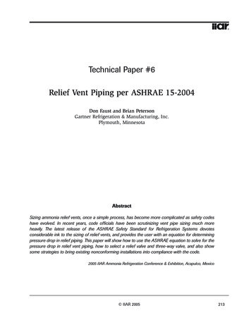
Order Independent Transparency with Per-Pixel Linked ListsPál Barta Balázs Kovács†Supervised by: László Szécsi‡ and László Szirmay-Kalos§Budapest University of Technology and EconomicsBudapest / HungaryAbstractThis paper proposes a method for rendering scenes of bothopaque and transparent objects. Transparency depends onthe attenuation coefficient and the thickness of the transparent object we wish to render. To get the visible radiance, the volume rendering equation should be solved.Instead of marching a ray, we build a list that containsthe intersection points of the ray and object surfaces. Inthe second phase of rendering, the GPU sorts and processes the lists and evaluates the attenuation integrals analytically, considering also the order of the segments. Thissolution is mathematically correct even if objects intersect,i.e. it does not involve drastic simplifications, and provideshigh framerates even on moderately complex scenes, outperforming previous methods. In addition to transparentobjects, the technique is also appropriate to visualize natural phenomena represented by particle systems.Keywords: Transparency, Direct3D 11, Linked-lists,GPU, Particle Systems.1IntroductionThe technique of alpha blending has a long history in twoand three-dimensional image synthesis. There are manyways to blend colors [10], but the most important issue isthat we can only get realistic results if we sort transparentobjects by their distance from the camera. Unfortunately,this requirement is not compatible with incremental rendering and z-buffer based visibility determination, whichallow the processing of objects in an arbitrary order. Sorting objects or even triangles in a way that occluders followobjects occluded by them is difficult and is usually impossible without further subdivision of objects. The problem is that an object is associated with a depth intervaland not with a single distance value, so no direct ordering relation can be established. A possible solution fornon-intersecting triangles is the application of the paintersalgorithm [1], but this has super-linear complexity and its brazil.hu@gmail.com† kockafely@gmail.com‡ szecsi@iit.bme.hu§ szirmay@iit.bme.huGPU implementation is prohibitively complicated.Figure 1: Order matters when the scene contains transparent objects.If objects may intersect each other, then the situationgets even worse. A typical case of intersecting transparentobjects are particle systems, which are tools to discretize,simulate and visualize natural phenomena like fog, smoke,fire, cloud, etc. The simplest way of their visualization applies planar billboards, but this approach results in abruptchanges where particles intersect opaque objects. The solution for this problem is the consideration of the sphericalextent of the particle during rendering, as proposed in theconcept of spherical billboards [9], also called soft particles. Spherical billboards nicely eliminate billboard clipping and popping artifacts at a negligible additional computational cost, but they may still create artifacts whereparticles intersect each other. Most importantly, when thez-order of billboards changes due to the motion of the particle system or the camera, popping occurs. This effect ismore pronounced if particles have non-identical colors ortextures.Instead of executing the sorting for the objects, we canas well ensure the correct order on the level of fragments.This approach does not require the sorting of the objects onthe CPU, which is emphasized by its name, order independent transparency. The family of such methods is usuallyreferred to as depth peeling. The basic idea of depth peeling is that the fragment shader may discard fragments thatare not farther than a previously selected threshold and thedepth buffer will identify the closest fragment from thenot discarded points. Thus, the scene is rendered multiple times and each time we ignore the already identifiedlayers. Intuitively, we peel layer surfaces from the scene.Depth peeling has been used in global radiosity [6] andin transparency [3, 8] calculation as well. Unfortunately,depth peeling needs to render the scene multiple times, de-Proceedings of CESCG 2011: The 15th Central European Seminar on Computer Graphics (non-peer-reviewed)
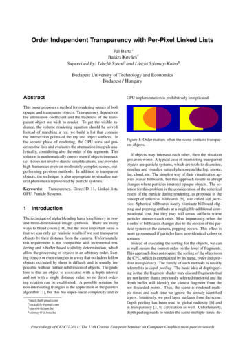
pending on the depth complexity of the scene (the depthcomplexity is defined as the maximum number of intersections a ray has in a given scene). Even its advanced versions, like Dual Depth Peeling [5], Reverse Depth Peeling[8] etc. could not be used effectively in real-time sceneswithout limiting the sorting to just the first few layers.AMD presented a special solution at the Game Developers Conference 2010 [4]. The latest series of ATI Radeonsupports DirectX11, which opened the door for new rendering algorithms. The latest Shader Model 5.0 GPUshave new features like the read/write structured buffers orthe atomic operations to manipulate them. Recall that before Shader Model 5.0, shaders may either read memory(e.g. input textures) or write it (e.g. render target), but notboth, and writes are always exclusive, so no synchronization is necessary. This limitation has been lifted by ShaderModel 5.0, and now we do not have to wait for the end ofa pass before reading back the result in a shader processor.With the use of these features, we are able to process theincoming fragments in a complex way instead of writingthem to the frame buffer. The fragments can be stored inlinked lists, which creates new ways to implement orderindependent alpha-blending.light not only on their boundary, but anywhere inside theirvolume. Participating media can be imagined as some material that does not completely fill the space. Thus the photons have the chance to go into the media and to travela random distance before collision. To describe light–volume interaction, the basic rendering equation should beextended [7, 2]. The volumetric rendering equation is obtained considering how the light goes through participating media (Figure 3).Figure 3: Change of radiance in participating media.The change of radiance L on a path of differential length⃗ depends on different phenomena:ds and of direction ωFigure 2: Model of a scene that contains opaque and transparent objects. Each transparent object is homogeneousand they can intersect each other.This paper proposes a new algorithm to render transparent, possibly intersecting objects and particles basedon DirectX11’s structured buffers and atomic operations.In Section 2, we first survey the model of light transportin homogeneous transparent objects. Then, in Section 3the new, GPU-based algorithm is discussed. Finally, wepresent results and conclusions.2Model of light transport in homogeneous objectsIn case of scenes having only opaque objects the radianceis constant along a ray and scattering may occur just onobject surfaces. Participating media, however, may scatterAbsorption and out-scattering: Photons may collidewith the material and the material may or may notreflect the photon after collision. The intensitychange is proportional to the number of photonsentering the path, i.e. the radiance and the probabilityof collision. If the probability of collision in a unitdistance is τ , then the probability of collision alonginfinitesimal distance ds is τ ds. After collision theparticle is reflected with the probability of albedoa, and absorbed with probability 1 a. Collisiondensity τ and the albedo may also depend on thewavelength of the light. Summarizing, the totalradiance change due to absorption and out-scatteringis τ Lds.In-scattering: Photons originally flying in a different direction may be scattered into the considered direction. The expected number of scattered photons fromdifferential solid angle dω ′ equals to the product ofthe number of incoming photons and the probability⃗ in distancethat the photon is scattered from dω ′ to ωds. The scattering probability is the product of thecollision probability (τ ds), the probability of not absorbing the photon (a), and the probability density of⃗ , given that the photon arthe reflection direction ω⃗ ′ , which is called phase funcrived from direction ωtion P(ω ′ , ω ). Following an ambient lighting model,we assume that the incident radiance is La in all directions and at every point of the scene. Taking intoaccount all incoming directions Ω′ , the radiance in-Proceedings of CESCG 2011: The 15th Central European Seminar on Computer Graphics (non-peer-reviewed)
crease due to in-scattering is: Thus, the exponential decay is: e τ ads La P(ω ′ , ω )dω ′ τ aLa ds s0τ (x)dxi 1 e τi (s si 1 ) e τ j (s j s j 1 ) .j 1Ω′since the phase function is a probability density, thusits integral over the full directional domain equals to1.Adding the discussed changes, we obtain the followingvolumetric rendering equation for the radiance L of a rayat s ds having taken step ds toward the eye:⃗ ) (1 τ ds)L(s, ω⃗ ) τ aLa ds.L(s ds, ω(1)Subtracting L(s) from both sides and dividing the equation by ds, the volumetric rendering equation becomes adifferential equation.⃗)dL(s, ω⃗ ) τ aLa . τ L(s, ω(2)dsIn homogeneous media, volume properties τ and a areconstant. In our model, the scene contains homogeneousobjects having different materials. Thus, in our case, theproperties are piece-wise constant functions along a ray. 2.1 Solution of the simplified volumetricequationThe radiance along a ray is described by an inhomogeneous first-order linear differential equation, which can besolved analytically. Assuming that the background radiance is zero, the radiance at the eye position (s 0) is:⃗) L(0, ω τ (s)a(s)La e s0τ (x)dxds0⃗ points from the pixel towards the eye.where direction ωLet us now exploit the fact that material properties a(s) andτ (s) are piece-wise constant functions, they may changewhere the ray intersects the surface of an object. Let usdenote the distance values of ray surface intersections bys1 , s2 , . . . , sn and extend this ordered list by s0 0 andsn 1 . The ray, i.e. the domain of the integration ispartitioned according to the segments between the intersection points, where albedo a(s) and attenuation parameter τ (s) are equal to ai and τi in segment [si 1 , si ), respectively:⃗) L(0, ωn 1 siτi ai La e s0τ (x)dxds.i 1si 1Then, we also partition the [0, s] interval according to theintersection points in the attenuation formula, assumingthat s is in [si 1 , si ]: s0i 1τ (x)dx τi (s si 1 ) τ j (s j s j 1 ).j 1Substituting this back into the eye radiance, we obtain:⃗) L(0, ωn 1 ai Li 1 siai 1τi e τi (s si 1 ) ds e τ j (s j s j 1 ) .j 1si 1We can obtain better quality rendering with shadingwithout significantly slowing down the rendering. We areusing Rayleigh shading where the phase function is:3(1 cos θ 2 )16πP(cos θ ) θ is the angle between the light and the view direction. Forsimplicity we assume the light source is directional, thuswe can foil the Rayleigh term before the integral because θwill be constant in a segment. Therefore we can substituteLa in our equations byLs La Lr3(1 cos θ 2 ).16πWe introduce a shorthand notation for the color contribution Ci of a segment: siCi ai Ls()τi e τi (s si 1 ) ds ai Ls 1 e τi (si si 1 ) .si 1(3)Note that this formula remains valid also for the τi 0case, i.e. when the ray travels in free space.Similarly to the contribution, segment transparency Tican also be applied to segment iTi e τ j (s j 1 s j ) .(4)With these shorthand notations, the radiance associatedwith a particular pixel is()⃗) L(0, ωn 1 i 1i 1Ci T j .(5)j 1The evaluation of this formula requires the intersection points to be sorted and segments to be visited in thesorted order. If the distances are sorted in ascending order,at each segment two equations should be evaluated iteratively, starting with L 0 and T 1:LT L Ci T,T · Ti .When the last segment is processed, variable L containsthe radiance of the ray.There are two critical issues concerning the iterativeevaluation of these formulae. First, segments should beProceedings of CESCG 2011: The 15th Central European Seminar on Computer Graphics (non-peer-reviewed)
stored and sorted on the GPU, without knowing in advance how many segments a particular ray has. On theother hand, the properties of the segments, including thealbedo and the attenuation parameter, should be determined from the object properties. As objects may intersecteach other, this question cannot be simply answered bychecking whose surface the ray has most recently crossed.These problems are solved by the algorithm presented inthe next section.3The rendering algorithmThe algorithm consists of two main steps: At first we collect every intersection point between all rays and objectsurfaces in lists associated with rays. Then, in the secondphase, the lists are sorted and processed to get the pixelcolors.3.1Data structuresIn order to get not only the first ray surface intersection,but all intersections of an eye ray, the latest features ofthe DirectX 11 compatible GPUs are exploited, includingstructured buffers and atomic writes.from the eye. We would like to store these valuesin a structure and build a list of them for each pixel.Instead of writing data to the frame buffer, we haveto store them in a special buffer called “Read/WriteStructured Buffer”. It is a generic buffer that containsthe declared type of structure. We have to appenda pointer to each structure, which addresses the nextfragment in the list. The value 1 as address denotesthe end of the list. The size of the buffer dependson the estimated amount of transparent fragments inthe viewing frustum. If the allocated memory is notenough for all the transparent fragments, then it willoverflow and we will lose important data. We set acounter for the buffer, its initial value is 0. When theshader appends a new structure of fragment data tothe buffer, the value of the counter will provide theaddress of the new element. Afterwards we increment the counter, so it always addresses the next freeslot in the Fragment and Link Buffer. We should update the counter with atomic operators, because it isparallely used by a number of shader units.Start Offset Buffer: The type of this buffer is the “ByteAddress Buffer”, which holds 4-byte addresses. Thefunction of this data structure is to refer to the firstelement of the linked list for every pixel. The first element is always the last fragment that was processedfor that list. When a new structure is appended, thepointer of the structure will get the value of the associated element in the “Start Offset Buffer”. Accordingly, we write the address of the newly storedstructure in the buffer. We have to allocate memoryto store one address for each pixel on the viewport.Opaque Scene Texture: This shader resource holds theRGB values of the opaque scene, and the distance ofthe fragment from the eye, which is stored in the alpha channel. When processing the list, the color readfrom this texture is also blended and the fragmentsbeing farther than this opaque fragment are discarded.Figure 4: Data structures.In particular, we use types of “Byte Address Buffer” and“Read/Write Structured Buffer”. The first type is used asthe starting element of the linked lists, while the buffer ofthe other type is filled with the fragment data structure. Weneed also a texture containing the opaque scene with depthinformation. The main data stores are the “Fragment andLink Buffer”, the “Start Offset Buffer”, and the “OpaqueScene Texture” (Figure 5).Fragment and Link Buffer: The output data of the firstphase pixel shader contains the radiance reflected atthe surface, the volumetric attenuation coefficient andthe albedo of the object, a flag whether or not the surface is front facing, and the distance of the fragment3.2 Collecting the fragmentsThe method starts with rendering opaque objects. Thealpha channel is used to store the distance of the fragment from the camera, so later the list of fragments canbe cropped based on this value.The next step is to render the transparent objects. Thedrawing function sets up the pipeline and passes the vertex information to the GPU. It is important that the cullingof the back-facing fragments must be disabled, otherwisethe GPU discards them and lot of important data aboutthe transparent scene will be lost. The vertex shader performs the standard transformations, the novel part of therendering comes with the pixel shader. When the pixelshader gets a fragment as input, it allocates and fills astructure, which contains the surface radiance, the volumetric attenuation and albedo, the distance from the cam-Proceedings of CESCG 2011: The 15th Central European Seminar on Computer Graphics (non-peer-reviewed)
era, and the orientation of the fragments. Then the shaderstores the structure in the “Fragment and Link Buffer” atthe next free slot and sets the “Start Offset Buffer” using the screen coordinates of the currently processed fragment. The pointer in the “Start Offset Buffer” at the address of the screen coordinate will reference this structure,and the pointer of the newly inserted structure gets the former value of the address buffer. This way a new elementis inserted into the linked list.3.3Loading and sorting the listsAfter the lists are created for each pixel and all the visiblefragment information is in the memory of the GPU, thesecond phase of the rendering begins. The next step is toparse each list in a local buffer, then sort the elements inascending order of the distance from the camera. Loading the lists into the local buffer of the shaders at first isimportant because working with local data is easier andfaster than reading each structure separately from a sharedresource. To avoid copying larger set of data, an indexbuffer should also be created, so during the sort the GPUmoves only indices instead of structures.3.4performs the best under the above mentioned conditionsand needs the lowest amount of memory space. Quicksortis one of the most popular sorting algorithms and itsoptimized versions are considered the fastest of them. Asa general rule this statement can be true, however, it is a bitmore complex than the simpler methods, which providesremarkable overhead. Additionally the current GPUs donot support recursive calls, and the basic quicksort is arecursive algorithm. Its non-recursive version needs alsoa stack to implement generating more overhead. In thecase of relatively small lists a much simpler algorithmcan perform better and the insertion sort is a popularchoice. Its disadvantages begin to come forward onlonger lists, while sorting an array of 100 items theinsertion sort outperforms the other sorting n/integers.html)Additionally its easy to implement, does not changethe relative order of elements with equal keys, onlyrequires a constant amount of additional memory spaceand performs even more faster on pre-sorted lists. Theseattributes makes us insertion sort the best choice here.3.5 Processing the listsThe sortingEvery sorting algorithm has its own characteristic, whichoffers advantages and disadvantages depending on theenvironment parameters of the sorting. These algorithmsare based on different concepts like partitioning, merging,selection or insertion, some of them providing biggeroverheads or different efficiency under different conditions. The implementation of the methods can also havea slight effect on their performance. At first we have togive an estimated number of the elements of the arraywe have to sort. In our case the fragments for each pixelare stored in these arrays, the GPU will sort each arrayindependently and will run the same sorting algorithmfor each pixel. So we have one array of fragments in ourshader code, which belongs to the currently processedpixel. Most of the cases the rendered scene contains sometransparent objects in an opaque environment, but even ifwe are experimen
z-order of billboards changes due to the motion of the par-ticle system or the camera, popping occurs. This effect is more pronounced if particles have non-identical colors or textures. Instead of executing the sorting for the objects, we can as