Transcription
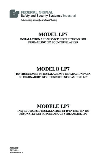
MODEL LP7INSTALLATION AND SERVICE INSTRUCTIONS FORSTREAMLINE LP7 SOUNDER/FLASHERMODELO LP7INSTRUCCIONES DE INSTALACION Y REPARACION PARAEL RESONADOR/ESTROBOSCOPIO STREAMLINE LP7MODELE LP7INSTRUCTIONS D’INSTALLATION ET D’ENTRETIEN DURÉSONATEUR/STROBOSCOPIQUE STREAMLINE LP72561493BREV. B 713Printed in U.S.A.
INSTALLATION AND SERVICE INSTRUCTIONS FOR STREAMLINELP7 SOUNDER/FLASHERSAFETY MESSAGE TO INSTALLERSPeople’s lives depend on your safe installation of our products. It is important to read,understand, and follow all instructions shipped with this product.Selection of mounting location for this device, its controls and routing of wiring shouldbe made by the Facilities Engineer and the Safety Engineer. Listed below are other important safety instructions and precautions you should follow. This unit must be installed and maintained by a qualified electrician in accordance withNational and local Electrical Codes, under the direction of the authority having jurisdiction. Do not connect this unit to system wiring when circuits are energized. For optimum sound distribution do not install this device where objects would blockthe front of the sounder. All effective warning horns produce loud sounds which, in certain circumstances, maycause permanent hearing loss. Take appropriate precautions such as wearing hearingprotection. Recommendations in OSHA Sound Level Standard (29 CFR 1910) shouldnot exceeded. After installation, be sure that all threaded joints are securely tightened. After installation and completion of initial systems test, a program for periodic testingof this device must be established. After installation and completion of initial system test, provide a copy of this instruction booklet to all personnel responsible for the operation, periodic testing, and maintenance of this equipment.I. GENERALThe Federal Signal Model LP7 sounder/strobe provides an audible and visual signalwhen activated remotely. The sounder is a polarized device rated at 18–28 Vdc. TheLP7 can provide 32 different tones with an adjustable volume located on the inside ofthe unit. For a list of tones, see Table 1.Electrical Details:Termination:Voltage Range:Starting Current:Running Current:Monitoring:Mechanical Details:Diameter:Overall Depth:IP Rating:Temp. range:Material:Screw terminals for 24 AWG to 14 AWG conductors.18 Vdc to 28 Vdc1.1 A for 1 ms68 mA averagePolarizing diode3.66 in (93 mm)Shallow Base: 3.6 in (91 mm)Deep Base: 4.72 in (120 mm]IP54 (Shallow Base), IP65 (Deep Base)‒10 C to 55 C (14 F to 131 F)ABS plastic body with polycarbonate lens-1-
II. INSTALLATIONA. UnpackingAfter unpacking the sounder, examine it for damage that may have occurred intransit. If equipment has been damaged, do not attempt to install or operate it. File aclaim immediately with the carrier stating the extent of the damage. Carefully checkall envelopes, shipping labels and tags before removing or destroying them.B. Mounting ArrangementsTo access mounting holes and electrical connections turn over the LP7 so the strobelens is facing down. Twist the base counter-clockwise to remove.The base of the LP7 provides six (6) slotted recesses for mounting, and one 15/32inch cable access hole.C. Electrical ConnectionsDANGERTo avoid electrical shock, do not attempt to connect wires when power is on.A terminal block is supplied on the LP7 for field wiring. Strip 1/2 inch of insulationfrom the wiring leads. Attach the appropriate wires to the corresponding terminals.Tighten the screws to insure that the wires are firmly held in place. The terminalswill accept conductor sizes 24 AWG to 14 AWG.III. TESTING/OPERATINGWARNINGUnder certain conditions these devices are capable of producing sound loud enough tocause hearing damage. Adequate hearing protection should be worn if standing withinclose proximity to the device while testing. Recommendations in OSHA SoundLevel Standard (29CFR 1910) should not be exceeded.After completion of installation be sure to test the system to verify that each sounderunit operates satisfactory.After completion of initial system test, a program for periodic testing of this deviceshould be established.Provide a copy of these instructions for the Safety Engineer(s), System Operators(s)and Maintenance personnel.SAFETY MESSAGE TO OPERATORSAlthough your warning system is operating properly it may not be completely effective.People may not hear or heed your warning signal. You must recognize this fact and ensure that your warning signal achieves its intended effect through proper test/trainingsequences suitable for your specific application(s).-2-
IV. MAINTENANCESAFETY MESSAGES TO MAINTENANCE PERSONNELFailure to follow all the safety precautions and instructions may result inproperty damage, serious injury, or death to you or others. Read and understand all instructions before performing maintenance on this unit. Do not perform maintenance on this unit when the circuit is energized. Periodic checks should be made to ensure that effectiveness of this device has not beenreduced because objects have been placed in front of the sounder. Any maintenance to this unit MUST be performed by a trained electrician in accordance with NEC guidelines and local codes. Never alter this unit in any manner. Safety may be jeopardized if alterations are madeto this device. The nameplates, which contain cautionary or other information of importance to maintenance personnel, should not be obscured if the exterior of the horn is painted.WARNINGUnauthorized servicing of this unit may result in diminished performanceand/or property damage, serious injury, or death to you or others. If a malfunctioningunit is encountered, do not attempt any field repair or retrofit of parts. Refer toparagraph V. SERVICE for instructions regarding return/repair of the unit.V. SERVICEThe factory will provide technical assistance with any problem that cannot be handledlocally with satisfaction. Please call customer service for assistance.Communication and shipments should be addressed to:Industrial SystemsService Department2645 Federal Signal DriveUniversity Park, IL 60484-3167 1 877 289 3246www.federalsignal-indust.comwww.fs-isys.com-3-
Figure 1 Wiring options and example of switch settingsStrobe and sounderoperate simultaneously21–VDC–VDCFeedthroughwires V DCSwitch VariantsExample of Tone 3 setting1HighVol 1LowVol2HighVol 1LowVol1V1 1 1012 3 4 5 61 1 1011 2 3 4 5ON1 2 3ONVOL1 2CIT4 56CIT3 45290A7060B-4-
262710988 Hz510 Hz14510 sSweepSweepSlow whoopSweep lternatingFrequency Hz800 and 970800 to 970800 to 97028502400 to 28502400 to 2850500 to 12001200 to 5002400 and 2850970800 and 9702850970970554 and 440660660660660554 and 4406602850800 to 9702400 to 2850970800 to 970970 and 800800 and 970990 and 650510 and 610300 to 1200510 and 610Rate2 Hz (250 ms-250 ms)7 Hz (7/s)1 Hz (1/s)Steady7 Hz1 Hz3 s sweep, 0.5 s silence, then repeat1 Hz2 Hz (250 ms-250 ms)0.5 Hz (1 s On/1 s Off)1 Hz (500 ms-500 ms)0.5 Hz (1 s On/1 s Off)0.8 Hz (250 ms On/1 s Off)Steady100 ms-400 ms3.3 Hz (150 ms On/150 ms Off)0.28 Hz (1.8 s On/1.8 s Off)0.05 Hz (13 s Off / 6.5 Hz On)Steady0.5 Hz (1 s On/1 s Off)1 Hz (500 ms-500 ms)4 Hz (150 ms On/100 ms Off)50 Hz50 Hz3 x 500 ms pulses, 1.5 s silence, then repeat3 x 500 ms pulsed sweep, 1.5 s silence, then repeat3 x 500 ms pulsed sweep, 1.5 s silence, then repeat2 Hz (250 ms-250 ms)2 Hz (250 ms-250 ms) (Symphoni tones)2 Hz (250 ms-250 ms) (Squashni Micro tones)1 Hz1 Hz (500 ms-500 ms)BS FireBS FireBS FireGeneral PurposeGeneral PurposeGeneral PurposeDutch Fire (NEN 2575)German Fire (DIN 33 404)General PurposePFEER alertBS FireGeneral PurposeGeneral PurposePFEER toxic gasFrench Fire (NFS 32-001)Swedish (Air raid)Swedish (Local warning)Swedish (Pre-mess)Swedish (All clear)Swedish (Turn out)Swedish General PurposePelican crossingBS FireGeneral PurposeISO 8201ISO 8201ISO 8201BS FireBS FireBS FireGeneral PurposeBS FireMain 831009996968324 V at 20 ºCTable 1 Siren tones-5-
INSTRUCCIONES DE INSTALACIÓN Y REPARACION PARA EL RESONA‑DORSTREAMLINE LP7MENSAJE DE SEGURIDAD PARA INSTALADORESLas vidas de las personas dependen de que usted instale con seguridad nuestros productos. Por lo tanto, es importante que lea, comprenda y siga todas las instrucciones quevienen con este producto.Las tareas de selección del lugar de montaje para este dispositivo, sus controles y el tendido de los cables deben ser realizadas por un ingeniero de instalaciones y un ingenierode seguridad. En la siguiente lista presentamos otras importantes instrucciones de seguridad y precauciones que usted debe observar sin falta. Esta unidad debe ser instalada y recibir mantenimiento por parte de un electricista calificado en conformidad con la norma los códigos eléctricos locales y nacionales, bajo ladirección de las autoridades que tengan jurisdicción sobre la materia. No conecte esta unidad al cableado de un sistema eléctrico mientras los circuitos esténrecibiendo energía eléctrica. Para lograr una óptima distribución del sonido, no instale este dispositivo en lugares enlos que habría objetos bloqueando la parte frontal del resonador. Todas las bocinas eficaces de emergencia producen sonidos sumamente fuertes que,en ciertas circunstancias, pueden causar la pérdida permanente de la audición. Tomelas precauciones apropiadas como, por ejemplo, usar protección para los oídos. No sedeben exceder los niveles recomendados en la Norma sobre niveles de sonido de laOSHA (29 CFR 1910). Después de su instalación, asegúrese de que todas las juntas roscadas queden firmemente apretadas. Después de instalar y completar la prueba inicial del sistema, se debe establecer unprograma para realizar periódicamente pruebas de este dispositivo. Después de instalar y completar la prueba inicial del sistema, entregue una copia deesta hoja de instrucciones a todo el personal encargado de operar este equipo, realizarpruebas periódicas de funcionamiento y darle mantenimiento.I. ASPECTOS GENERALES.El resonador/destellador Modelo LP7 de Federal Signal proporciona una señal sonoray visual al ser activado por un panel de control situado a distancia. El resonador es undispositivo polarizado con una capacidad nominal de 18–28 Vcc. El resonador es apropiado para los sistemas supervisados de alarma contra incendio. El LP7 puede emitir32 tonos diferentes con un volumen ajustable situado en la parte interior de la unidad.Vea la tabla 1 para una lista de tonos.Detalles Eléctricos:Terminación:Límites de voltaje:Corriente inicial:Corriente normal de marcha:Medio de supervisión:terminales de tornillo para conductores calibre 24 AWGa 14 AWG18 a 28 voltios de corriente continua1.1 A durante 1 milisegundos68 mA comúndiodo polarizante-6-
Detalles Mecánicos:Diámetro:Profundidad general:Calificación IP:Gama de temperaturas:Material:3,66" (91 mm)base bajo: 3,6" (91 mm), base de hondo: 4,72" (120 mm)IP54 (base bajo), IP65 (base de hondo)‒10 C a 55 C (14 F a 131 F )Plástico de resina ABSII. INSTALACIONA. DesembalajeDespués de desembalar el resonador, examínelo para ver si sufrió algún daño durante el transporte. Si el equipo se ha dañado, no intente instalarlo ni ponerlo en funcionamiento. Presente una reclamación inmediatamente ante el transportista especificando la extensión de los daños. Revise cuidadosamente todos los sobres, etiquetasde envío y rótulos antes de sacarlos o destruirlos.B. Medios de MontajeSaque la cubierta superior tirando de ella hacia atrás con un ligero movimiento debalanceo de lado a lado.PRECAUCIONSi tuerce la cubierta puede romper los rebordes de la cubierta e inutilizar la placa decubierta.La base del LP7 proporciona seis hendiduras ranuradas para el montaje y un orificiode acceso de 15/32 pulg para el cable.C. Conexiones EléctricasPELIGROPara evitar descargas eléctricas, no intente conectar los cables mientrasle esté llegando electricidad al circuito.El LP7 tiene un bloque de terminales para el cableado sobre el terreno. Pele un cuarto pulgada del forro de los cables. Empalme los cables apropiados a los terminalescorrespondientes. Apriete los tornillos para asegurarse de que los cables quedenfirmemente en su sitio. En los terminales se pueden instalar conductores calibre24 AWG a 14 AWG.III. PRUEBAS/OPERACIONADVERTENCIABajo ciertas condiciones estos dispositivos pueden producir sonidos tan fuertes que pueden causar daños para la audición. Se debe usar una adecuada protección para los oídos sise está cerca del dispositivo durante las pruebas. No se debe exceder la Normasobre niveles de sonido OSHA (29 CFR 1910).Después de completar la instalación, asegúrese de probar el sistema para verificarque cada unidad de resonador funcione en forma satisfactoria.Después de completar la prueba inicial del sistema, se debe establecer un programapara las pruebas periódicas de este dispositivo.-7-
Usted debe entregar un ejemplar de estas instrucciones al ingeniero(s) de seguridad,los operadores del sistema y el personal de mantenimiento.MENSAJE DE SEGURIDAD PARA LOS OPERADORESAunque su sistema de alarma esté funcionando correctamente, es posible que no seacompletamente efectivo. Puede ocurrir que la gente no escuche o no preste atención a laseñal de advertencia. Usted debe tener en cuenta esta posibilidad y asegurarse de que suseñ
INSTRUCCIONES DE INSTALACION Y REPARACION PARA . EL RESONADOR/ESTROBOSCOPIO STREAMLINE LP7. MODEL LP7. INSTALLATION AND SERVICE INSTRUCTIONS FOR . STREAMLINE LP7 SOUNDER/FLASHER. 2561493B. REV. B 713 Printed in U.S.A. INSTALLATION AND SERVICE INSTRUCTIONS FOR STREAMLINE . LP7 SOUNDER/FLASHER SAFETY MESSAGE TO