Transcription
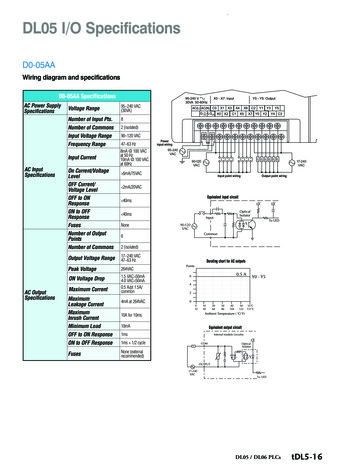
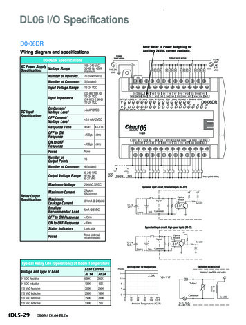
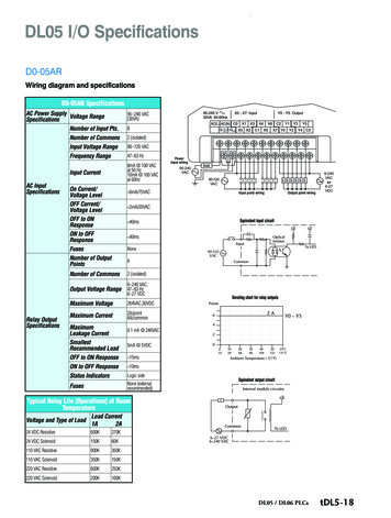
.DL05 I/O SpecificationsD0-05ARWiring diagram and specificationsD0-05AR SpecificationsAC Power Supply Voltage RangeSpecificationsNumber of Input Pts.AC InputSpecificationsRelay OutputSpecifications95–240 VAC(30VA)8Number of Commons2 (isolated)Input Voltage Range90–120 VACFrequency Range47–63 HzInput Current8mA @ 100 VACat 50 Hz10mA @ 100 VACat 60HzOn Current/Voltage LevelOFF Current/Voltage LevelOFF to ONResponseON to OFFResponseFusesNumber of OutputPointsPowerinput wiring95-240VAC90-120VAC 6mA/75VACInput point wiringOutput point wiring6-240VACor6-27VDC 2mA/20VACEquivalent input circuit 40ms 40msNone6Number of Commons2 (isolated)Output Voltage Range6–240 VAC,47–63 Hz6–27 VDCMaximum Voltage264VAC,30VDCMaximum Current2A/point6A/commonMaximumLeakage CurrentSmallestRecommended LoadOFF to ON Response 9 &Derating chart for relay outputs0.1 mA @ 246VAC5mA @ 5VDC 15msON to OFF Response 10msStatus IndicatorsLogic sideFusesNone (externalrecommended)Equivalent output circuitTypical Relay Life (Operations) at RoomTemperatureVoltage and Type of LoadLoad Current1A2A24 VDC Resistive600K270K24 VDC Solenoid150K60K110 VAC Resistive900K350K110 VAC Solenoid350K150K220 VAC Resistive600K250K220 VAC Solenoid200K100KDL05 / DL06 PLCstDL5-18
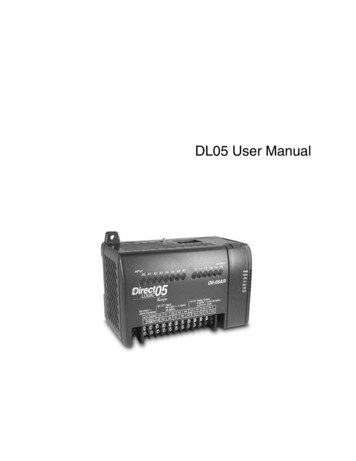
.Features at a GlanceThe DL05 and DL06 micro PLCs arecomplete self-contained systems. The CPU,power supply, and I/O are all includedinside the same housing. Option modulesare available to expand the capabilityof each PLC family for more demandingapplications. The standard features of thesePLCs are extraordinary and compare favorably with larger and more expensive PLCs.The specification tables to the right aremeant for quick reference only. Detailedspecifications and wiring information foreach model of the DL05 and DL06 PLCscan be found in those specific sections.Program capacityMost boolean ladder instructions requirea single word of program memory. Otherinstructions, such as timers, counters, etc.,require two or more words. Data is stored inV‑memory in 16-bit registers.PerformanceThe performance characteristics shown in thetables represent the amount of time requiredto read the inputs, solve the Relay LadderLogic program and update the outputs.InstructionsA complete list of instructions is availableat the end of this section.CommunicationsThe DL05 and DL06 offer powerfulcommunication features normally foundonly on more expensive PLCs.Special featuresThe DC input and DC output PLCs offerhigh-speed counting or pulse output.Option module slots allow for discreteI/O expansion, analog I/O, or additionalcommunication options.DL05 CPU SpecificationsSystem capacityTotal memory available (words) 14.8KLadder memory (words) 7680V-memory (words) 7616User V-memory 7488Non-volatile user V-memory 128Built-in battery backup (D2-BAT-1) YesTotal I/O 36Inputs 20Outputs 16I/O expansion Yes1PerformanceContact execution (Boolean) 0.6 µsTypical scan (1K Boolean)2 1-2 ms.Contact execution (Boolean) 0.7 µsTypical scan (1K Boolean)2 1.5-3 ms.Instructions and diagnosticsRLL ladder style YesRLLPLUS/flowchart style (Stages) Yes/256Run-time editing YesSupports Overrides YesScan Variable/fixedNumber of Instructions 133Types of Instructions:Control relays 512Timers 128Counters 128Immediate I/O YesSubroutines YesFor/next loops YesTimed interrupt YesInteger math YesFloating-point math NoPID YesDrum sequencers YesBit of word YesASCII print YesReal-time clock/calendar Yes1Internal diagnostics YesPassword security YesSystem and user error log NoCommunicationsBuilt-in ports Two RS-232CProtocols supported:K-sequence (proprietary protocol) YesDirectNet master/slave YesModbus RTU master/slave YesASCII out YesBaud ratePort 1 9,600 baud (fixed)Port 2 selectable 300-38,400 baud (default 9,600)Specialty FeaturesFiltered inputs Yes3Interrupt input Yes3High speed counter Yes, 5kHz3Pulse output Yes, 7kHz3Pulse catch input Yes32- Our 1K program includes contacts, coils, andscan overhead. If you compare our productsto others, make sure you include their scanoverhead.3- Input features only available on units with DCinputs and output features only available onunits with DC outputs.DL05 / DL06 PLCsSystem capacityTotal memory available (words) 6KLadder memory (words) 2048V-memory (words) 4096User V-memory 3968Non-volatile user V-memory 128Battery backup Yes1Total built-in I/O 14Inputs 8Outputs 6I/O expansion Yes11- These features are available with use ofcertain option modules. Option module specifications are located later in this section.tDL5-3DL06 CPU SpecificationsPerformanceInstructions and diagnosticsRLL ladder style YesRLLPLUS/flowchart style (Stages) Yes/1024Run-time editing YesSupports Overrides YesScan Variable/fixedNumber of Instructions 229Types of Instructions:Control relays 1024Timers 256Counters 128Immediate I/O YesSubroutines YesFor/next loops YesTable functions YesTimed interrupt YesInteger math YesTrigonometric functions YesFloating-point math YesPID YesDrum sequencers YesBit of word YesNumber type conversion YesASCII in, out, print YesLCD instruction YesReal-time clock/calendar YesInternal diagnostics YesPassword security YesSystem and user error log NoCommunicationsBuilt-in ports: One RS-232C One multi-function RS232C/RS422/RS485NOTE: RS485 is for MODBUS RTU only.Protocols supported:K-sequence (proprietary protocol) YesDirectNet master/slave YesModbus RTU master/slave YesASCII in/out YesBaud ratePort 1 9,600 baud (fixed)Port 2 selectable 300-38,400 baud (default 9,600)Specialty FeaturesFiltered inputs Yes3Interrupt input Yes3High speed counter Yes, 7kHz3Pulse output Yes, 10kHz3Pulse catch input Yes31- T hese features are available with use ofcertain option module. Option module specifications are located later in this section.2- O ur 1K program includes contacts, coils, andscan overhead. If you compare our productsto others, make sure you include their scanoverhead.3- I nput features only available on units with DCinputs and output features only available onunits with DC outputs.
.Features at a GlanceDirectSOFT softwareThe DL05 and DL06 PLCs use the samefamiliar DirectSOFT programming software that our larger PLCs use. A FREEversion of DirectSOFT gives you all thegreat features of the full version, but witha 100-word PLC program downloadlimitation. For programs larger than 100words, the full package is required. TheFREE PC-DS100 software may be sufficient to program the DL05 and DL06. Ifyou are programming with a full packageversion prior to v6.0, you will need v2.4 orlater for the DL05 PLCs and v4.0 or laterfor the DL06. We always recommend thelatest version for the most robust features.See the DirectLOGIC Overview sectionDL in this catalog for a complete description of DirectSOFT including features, partnumbers of programming packages andupgrades.ProgrammingHandheld programmer.D2-HPP . . . . . . . . . . . . . . .DirectSOFT Programming for WindowsPC-DSOFT6. . . . . . . . . . . . . . . . . . . . . . . . . . . . . . . .PC-DS100. . . . . . . . . . . . . . . . . . . . . . . . . . . . . . . . . . . . . . FreePC-R60-U (upgrade) . . . . . . . . . . . . . . . . . . . . . . . . .External power inputsMounting tabInput status indicatorsMode switchCommunication portsOutput status indicatorsMode statusindicatorsCommunication statusindicatorsRemovableterminalblockExternal power inputsDiscrete output terminalsDiscrete input terminalsDiscrete output terminalsOption module slotHardware features diagramsRemovableterminalblockOption module slotsMode statusindicatorsOutput status indicatorsInput status indicatorsCommunication statusindicatorsMode switchDiscrete input terminalsRemovableterminalblockCommunication portsMounting tabDL05 / DL06 PLCstDL5-4
.Product Dimensions and InstallationIt is important to understand the installation requirements for your DL05 or DL06system. Your knowledge of these requirements will help ensure that your systemoperates within its environmental andelectrical limits.Note: T here is a minimum clearance requirementof 2” (51mm) between the panel door(or any devices mounted in the panel door)and the nearest DL05 component.Plan for safetyThis catalog should never be used as areplacement for the user manual. You canpurchase, download free, or view onlinethe user manuals for these products. TheD0-USER-M is the publication for theDL05 PLCs, and the D0-06USER-M isthe publication for the DL06 PLCs. TheD0-OPTIONS-M is the user manual forthe option modules. These user manualscontain important safety information thatmust be followed. The system installationshould comply with all appropriate electrical codes and standards.Temperature probe2"50mmminPower source2"50mmmin2"50mmminPanel ground terminalBus barPanelStar washersEarthgroundGround braid copper lugsStar washersPanel or singlepoint groundSee the Enclosuresection to find an enclosurethat fits your applicationTemperature probe1.5"38mmminEnvironmental Specificationsfor DL05 and DL06Power source1.5"38mmminAmbient OperatingTemperaturePanel ground terminalBus barEarthgroundNote: There is a minimum clearance requirement of 1.5” (38mm)between the panel door (or any devices mounted in thepanel door) and the nearest DL06 component.tDL5-5DL05 / DL06 PLCsStorage Temperature1.5"38mmminAmbient Humidity-4º F-158ºF(-20ºC to 70ºC)32ºF-131ºF(0º to 55ºC)5 to 95% relativehumidity(non-condensing)Vibration ResistanceMIL STD 810CMethod 514.2Shock ResistanceMIL STD 810CMethod 516.2Noise ImmunityNEMA (ICS3-304)AtmosphereNo corrosive gases
.Product Dimensions and InstallationUnit dimensions andmounting orientationDL05 and DL06 PLCs must be mountedproperly to ensure ample airflow forcooling purposes. It is important to followthe unit orientation requirements andto verify that the PLC’s dimensions arecompatible with your application. Noticeparticularly the grounding requirementsand the recommended cabinet clearances.Mounting orientationMounting orientationDL05 / DL06 PLCstDL5-6
.Ports, Status Indicators, and ModesPort 1Port 1 is a 6-pin, fixed configuration portand has the same pin assignments on theDL05 and the DL06. Please refer to the tableand diagrams on this page. This port can beused to connect to an HPP, DirectSOFT, anoperator interface, or other external device.Features include: 9600 baud 8 data bits Odd parity 1 start bit, 1 stop bit Station address of 1 Asynchronous, half-duplex, DTEProtocols supported (as slave): K sequence, DirectNET, Modbus RTUDL05 & DL06 Port 1 Pin Descriptions1234560VPower (-) connection (GND)Port 2Port 2 is a configurable port on both theDL05 and the DL06 PLCs. The DL05 PLCuses a 6-pin modular connector and offersRS-232 communications only. The DL06PLC uses a 15-pin HD-sub connectorand offers RS-232, RS-422, or RS-485communications. Please refer to the tableand diagrams on this page for more information. This port can be used to connectto an HPP, DirectSOFT, an operator interface, or other external device. Features ofport 2 include: 300, 600, 1200, 2400, 4800, 9600 (default),19,200, 38,400 baud 8 data bits Odd (default), even, or no parity 1 start bit, 1 stop bit Station address:5VPower ( ) connection1 (default)RXDReceive data (RS-232C)TXDTransmit data (RS-232C)1-90 DirectNET, K sequence5VPower ( ) connection0VPower (-) connection (GND)DL05 Port 2 Pin Descriptions1234560VPower (-) connection (GND)5VPower ( ) connectionRXDReceive data (RS-232C)TXDTransmit data (RS-232C)RTSReady to send0VPower (-) connection (GND)DL06 Port 2 Pin Descriptions6-pin Female Modular ConnectorDL066-pin FemaleModular Connector15-pin FemaleD-sub ConnectorStatus IndicatorsIndicator Status MeaningPWRRUNCPU1234567891011121314155VPower ( ) connectionTXDTransmit data (RS-232C)RXDReceive data (RS-232C)RTSReady to send (RS232C)CTSClear to send (RS232C)RXD-Receive data (-) (RS-422/485)0VPower (-) connection (GND)0VPower (-) connection (GND)ONPower goodOFFPower failureONCPU is in Run ModeOFFCPU is in Stop or Program ModeONCPU self diagnostics errorOFFCPU self diagnostics goodONData is being transmitted by theCPU-Port 1OFFNo data is being transmitted bythe CPU-Port 1ONData is being received by theCPU-Port 1OFFNo data is being received by theCPU-Port 1ONData is being transmitted by theCPU-Port 2OFFNo data is being transmitted bythe CPU-Port 2ONData is being received by theCPU-Port 2OFFNo data is being received by theCPU-Port 2TX1RX1TX21-247 Modbus RTU Asynchronous, half-duplex, DTEProtocols supported: K sequence (slave), DirectNET(master/slave), Modbus (master/slave)DL05DL05 and DL06 statusindicatorsRX2DL05 and DL06 modeswitchesModeSwitchPositionCPU ActionCPU is forced into the RUN mode if noRUN (Run errors are encountered. No programare allowed by the programProgram) changesming/monitoring device.RUN PROGRAM and the TEST modes areTERMavailable. Mode and program changesallowed by the programming/moni(Terminal) aretoring device.STOPCPU is forced into the STOP mode. Nochanges are allowed by the programming/monitoring device.Use the optional low profile 15-pin adapterto make option module wiring easier.D0-06ADPTRTXD Transmit data ( ) (RS-422/485TXD-Transmit data (-) (RS-422/485)RTS Ready to send ( ) (RS-422/485)RTS-Ready to send (-) (RS-422/485)RXD Receive data ( ) (RS-422/485)CTS Clear to send ( ) (RS-422/485)CTS-Clear to send (-) (RS-422/485)DL05 / DL06 PLCstDL5-10
DL05 and DL06 status indicators DL05 and DL06 mode switches 6-pin Female Modular Connector 6-pin Female Modular Connector 15-pin Female D-sub Connector Port 1 Port 1 is a 6-pin, fixed configuration port and has the same pin assignments on the DL05 and the DL06. Please refer to the table and diagrams on this page. This port can be