Transcription
QSI-i Series50-200 HorsepowerDirect Drive Industrial Air CompressorsInstruction ManualThis manual contains important safety information and should be made available toall personnel who operate and/or maintain this product. Carefully read this manualbefore attempting to operate or perform maintenance on this equipment.Manual No. 2012203634December 2012 Edition
Table of ContentsSection I - General InformationSafety Alert Symbols .1Safety Precautions .2Spare Parts Ordering Information .3Serial/Model Identification Plate .3Royal Blue Warranty . 4-5Section II - DescriptionGeneral Description .6The Compression Cycle .6Air Flow .7Cooling System .7Capacity Control.8Control Options .8Operating Modes .9Electrical System.10Indicators .11Gauges .11Section III - InstallationReceiving .12Moving the Unit to the Installation Site .12Location .13Piping Connections .14Relief Valves.14Electrical .15Guards .15Manual Vent and Shutoff Valve.16Water and Sewer Facilities at the Installation Site (water-cooled) .16Intake Air .16Compressor Rotation.17Fan Rotation (air-cooled) .17Section IV - Operating ProceduresPrior to Starting .18Starting the Compressor .19Stopping the Compressor .19PLC Controller Operation (gauge machine) . 20-21Electronic Controller Operation . 22-27Section V - Integrated Dryer (option)General Information .28Inspection .28Safety .28Installation .29Start-up & Operation .29Maintenance .30Automatic Drains .31Particle Strainer .32Quincy Compressor-QSI
Table of ContentsCompressor .32Expansion Valve.32Hot Gas Bypass Valve .33Dual Pessure Switch .33Troubleshooting .35Section VI - ServicingPreparing for Maintenance or Service .36Safety .36Maintenance Schedule .37Water Removal .38Air/Fluid Separator Element .38Fluid Scavenging System .39Air Filter .39Fluid Filter .40Shaft Seal .41Air and Fluid Tubing .43Service Adjustments .43Water Coolers .45Section VII - Compressor FluidsFluid Specifications.46Lubrication .47Fluid Level .47Fluid Sample Valve .48Factors Affecting Fluid Life .48Sampling Procedures.49Fluid Analysis Program - General .50Understanding the Analysis Report .52QuinSyn-Plus .53QuinSyn-PG .54QuinSyn-XP .55QuinSyn-F .56QuinSyn Flush.56Cleaning and Flushing With QuinSyn Flush .57Converting to QuinSyn-Plus .58Converting to QuinSyn-PG .58Converting to QuinSyn-XP .59Fluid Parameters .60Section VIII - TroubleshootingTroubleshooting . 62-71Appendix A - Dimensional DrawingsDimensional Drawings . 72-73Appendix B - Technical DataTechnical Data .74Addendum 1 - QSIi Standard Electronic Control . 75-92Standard Terms and Conditions. 93-94Quincy Compressor-QSI
Section I - General Information Safety Alert SymbolsSafety PrecautionsSpare Parts Ordering InformationSerial/Model Identification PlateRoyal Blue WarrantySafety Alert SymbolsIMPORTANT!Throughout this manual we have identified key hazards. The following symbols identifythe level of hazard seriousness:DANGER!This symbol identifies immediatehazards which will result in severepersonal injury, death or substantialproperty damage.WARNING!This symbol identifies hazards or unsafepractices which could result in personalinjury, death or substantial propertydamage.DANGER!This symbol identifies life threateningelectrical voltage levels which will resultin severe personal injury or death. Allelectrical work must be performed bya qualified electrician.CAUTION!Identifies hazards or unsafe practiceswhich could result in minor personalinjury or property damage.NOTICE!CAUTION!This symbol identifies hot surfaceswhich could result in personal injury orproperty damage.Identifies important installation,operation or maintenance informationwhich is not hazard related.Quincy Compressor-QSI 1
Section I - General InformationSafety PrecautionsRead this manual and follow all instructionsprior to installing or operating thecompressor.Listed below are some, but not all, safetyprecautions that must be observed withcompressors and compressed air systems.WARNING!Failure to follow any of these precautionsmay result in severe personal injury,death, property damage and/orcompressor damage. Air from this compressor will causesevere injury or death if used forbreathing or food processing. Airused for these processes mustmeet OSHA 29 CFR 1910.134 orFDA21XDE178.3570 regulations. Disconnect and lockout all powersupplies to the compressor plus anyremote controllers prior to servicing theunit. Never assume it is safe to work on thecompressor because it is not operating.Many installations have automatic start/stop controls and the compressor maystart at any time.2 A properly sized pressure relief valvemust be installed in the dischargepiping ahead (upstream) of any shutoffvalve (block valve), heat exchanger,orifice or any potential blockagepoint. Failure to install a pressurerelief valve could result in the rupturingor explosion of some compressorcomponent. Do not change the pressure setting ofthe pressure relief valve, restrict thefunction of the pressure relief valve, orreplace the pressure relief valve witha plug. Over pressurization of systemor compressor components can occur,resulting in death, severe personalinjury or property damage. Never use plastic pipe, rubber hose,or soldered joints in any part of thecompressed air system. Failure toensure system compatibility withcompressor piping is dangerous. Never use a flammable or toxic solventfor cleaning the air filter or any parts. Do not remove any guards or cabinetpanels or attempt to service anycompressor part while the compressoris operating. Do not operate the compressor atpressures in excess of its rating. This compressor is designed for use inthe compression of normal atmosphericair only. No other gases, vapors orfumes should be exposed to thecompressor intake, nor processedthrough the compressor. Observe control panel displays dailyto ensure compressor is operatingproperly. Relieve all pressure internal to thecompressor prior to servicing. Do notdepend on check valves to hold systempressure. Never disconnect or tamper with thehigh air temperature (HAT) sensors. Follow all maintenance procedures andcheck all safety devices on schedule. Compressed air is dangerous, do notplay with it.Quincy Compressor-QSI
Section I - General Information Use the correct fluid at all times. Do not rely on the discharge air linecheck valve. Do not override any safety or shutdowndevices. Keep doors closed during operation.The operating temperature of somecomponents is sufficient to burn theskin.NOTICE!Every effort has been taken to ensurecomplete and correct instructions havebeen included in this manual, however,possible product updates and changesmay have occurred since this printing.Quincy Compressor reserves theright to change specifications withoutincurring any obligation for equipmentpreviously or subsequently sold. Notresponsible for typographical errors.NOTICE!T h e s e i n s t r u c t i o n s , p re c a u t i o n sand descriptions cover standardQuincy manufactured QSI Seriesair compressors. As a service toour customers, we often modify orconstruct packages to the customersspecifications. This manual may not beappropriate in those cases.Spare Parts Ordering InformationSerial/Model Identification PlateQuincy Compressor maintains replacementparts for Quincy compressors andaccessories. A repair parts list is shippedwith all new machines. Order parts fromyour Authorized Quincy distributor. Useonly genuine Quincy replacement parts.Failure to do so may void warranty.Reference to the machine MODEL, SERIALNUMBER and DATE OF ORIGINAL STARTUP must be made in all communicationrelative to parts orders. A model/serialnumber plate is located on the frame or inthe upper right corner of the control paneldoor.Quincy Compressor-QSI 3
Section I - General InformationRoyal Blue WarrantyQuincy Compressor Industrial Screw ProductsQSI -i Series 50-200 HP (150 psig & below)Direct Drive Rotary Screw Air CompressorsSeller warrants products of its own manufactureagainst defects in workmanship and materialsunder normal use and service, as follows:QSI Packaged Compressors - Twelve (12)months from date of start-up or twenty-four(24) months from date of shipment from thefactory, whichever occurs first.Airend on Packaged Compressors (for serviceat full-load pressure at or below 150 psig) - Tenyears (120 months) from date of startup (notto exceed 126 months from date of shipmentfrom the factory).Airend on Packaged Compressors (for serviceat full-load pressure above 150 psig) - Twelve(12) months from date of start-up or twenty-four(24) months from date of shipment from thefactory, whichever occurs first.Air/fluid Reservoir Tank - Five years (60 months)from date of start up (not to exceed 66 monthsfrom date of shipment), including parts andlabor. In the event of a reservoir tank failure,the parts and labor coverage is limited to thereservoir tank itself and does not cover theseparator element(s) or loss of fluid.Air and Fluid Heat Exchangers - Five years (60months) from date of start up (not to exceed 66months from date of shipment), including partsand labor for the first twelve (12) months, partsonly after twelve (12) months. In the event ofa heat exchanger failure, the parts and laborcoverage is limited to the heat exchanger itselfand does not cover the loss of fluid.Drive Motor - Five years (60 months) from dateof start up (not to exceed 66 months from dateof shipment), including parts and labor. RoyalBlue warranty does not cover medium voltage(above 575 volt, 3 phase) motors. Before anymotor repairs or replacements are performed,the factory must be contacted at the time offailure in order to approve any further action.Drive Coupling Element - Five years (60 months)from date of start up (not to exceed 66 monthsfrom date of shipment), including parts andlabor. (Machine must be installed and operatedin accordance with the Operator’s Manual.)4Variable Speed Drives (if applicable) - Fiveyears (60 months) from date of start up (notto exceed 66 months from date of shipment),including parts & labor for the first year (12months), parts only for the remainder ofthe warranty period. Unit must be installedindoors in a well ventilated environment& a line reactor purchase (from QuincyCompressor) is required.Remanufactured Airend - Twelve (12) monthsfrom date of shipment from the factory.Parts - Ninety (90) days from date of Distributorsale or one (1) year from date of factoryshipment.With respect to products not manufactured bySeller, Seller will, if practical, pass along thewarranty of the original manufacturer.The terms of coverage for the Royal BlueWarranty are listed below. Failure to follow theterms will invalidate the Royal Blue Warranty.AUTHORIZED START-UP REQUIRED:A properly completed start-up report and theRoyal Blue Warranty registration form must besubmitted by an authorized Quincy distributorto the Quincy Compressor Bay Minette officewithin thirty (30) days of start-up. Start-upreports must be submitted on Q-Serv.GENUINE PARTS AND FLUIDSThe compressor must be maintained withQuinSyn-PG (8,000 hours maximum), QuinSynXP (12,000 hours maximum), QuinSyn-Plus(8,000 hours maximum) or QuinSyn-F fluid(4,000 hours maximum). Maximum fluid changeintervals are noted per fluid. Actual fluid changeinterval is to be determined by fluid samplingreport, not to exceed maximum fluid changeinterval. Fluid samples must be taken every2,000 hours or as directed by the analysisreport.Only genuine Quincy Compressor maintenanceand replacement parts may be used on thecompressor.Quincy Compressor-QSI Revised airend coverage (05/21/07).
Section I - General InformationRoyal Blue WarrantyQuincy Compressor Industrial Screw ProductsQSI -i Series 50-200 HP (150 psig & below)Direct Drive Rotary Screw Air CompressorsNormal rules of warranty apply regardless ofcoverage length. Inlet valves, fluid pumpsand shaft seals are covered by the standard (1year) warranty terms and are not included inthe Royal Blue Warranty program. The RoyalBlue Warranty is non-transferable.Seller warrants factory repaired or replacedparts of its own manufacture against defectsin material and workmanship under normaluse and service for ninety (90) days or for theremainder of the warranty on the productbeing repaired, whichever is longer.The customer and/or Quincy Distributormust keep copies of all maintenance records,parts purchases and sampling reports.The following records will be required forwarranty airend replacement and/or warrantyclaim consideration and should be submittedto the Quincy Compressor Customer ServiceDepartment:This warranty shall not apply and Seller shallnot be responsible nor liable for:A completed Airend Failure Informationform.A copy of the Royal Blue WarrantyRegistration/ Agreement form.Copies of all maintenance logs for theunit.Proof of purchase of genuine Quincyparts and fluids.Copies of all fluid analysis reports.Notice of the alleged defect must be givento Seller in writing with all identifying detailsincluding serial number, model number, typeof equipment and date of purchase, withinthirty (30) days of the discovery of sameduring the warranty period.Seller’s sole obligation on this warrantyshall be, at its option, to repair, replace orrefund the purchase price of any product orpart thereof which proves to be defective.If requested by Seller, such product or partthereof must be promptly returned to Seller,freight collect for inspection.a) Consequential, collateral or speciallosses or damages;b) Equipment conditions caused by fairwear and tear, abnormal conditionsof use, accident, neglect or misuseof equipment, improper storage ordamages resulting during shipment;c) Deviation from operating instructions,specifications, or other special termsof sales;d) Labor charges, loss or damageresulting from improper operation,maintenance or repairs made byperson(s) other than Seller or Seller’sauthorized service station.e) Improper application of product.In no event shall Seller be liable for anyclaims, whether arising from breach ofcontract or warranty of claims of negligenceor negligent manufacture, in excess of thepurchase price.NOTICE!Quincy Compressor reserves the rightto modify or withdraw this Royal BlueWarranty program at any time on unitsnot already covered by this ROYALBLUE WARRANTY program.Quincy Compressor-QSI 5
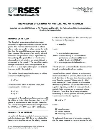
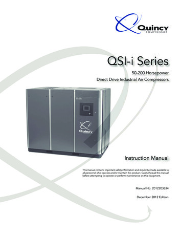
Section II - Description General Description The Compression Cycle Air Flow Cooling System Capacity Control Control Options Operating Modes Electrical System Indicators GaugesGeneral DescriptionThe Compression CycleQSI compressors are single stage, positivedisplacement, fluid-flooded rotary screwtype compressors containing two precisionmachined rotors. A motor directly drivesthe male rotor through a flexible drop outtype coupling with no step up or step downgearing used. The male rotor has four lobesthat mesh with a female rotor consisting ofsix flutes. Both rotors are housed in a singlecast iron cylinder. The unit has an inlet portat the power input end and a discharge portat the opposite end.The compression cycle of a rotary compressoris a continuous process from intake todischarge with no reciprocating mechanismsstarting and stopping as found in reciprocatingcompressors. The compressor consists of tworotors in constant mesh, housed in a cylinderwith two parallel adjoining bores. The maledrive rotor has four lobes that mesh withsix flutes in the female rotor. All parts aremachined to exacting tolerances.Some models are equipped with a positivedisplacement fluid pump mounted to thecompressor to circulate fluid through thesystem. Models without a fluid pump usepositive pressure in the reservoir to circulatethe fluid.All components are attached to a heavyduty steel frame. Controls and indicatorsare arranged on a control panel. Acousticalcabinets are available to reduce soundlevels.INLET PORTAs the rotors rotate, (male-clockwise as viewedfrom the power input end) air is drawn into thecylinder through the inlet port located at thepower input end. A volume of air is trapped asthe rotor lobes pass the inlet cut off points inthe cylinders. Compression occurs as the malerotor rolls into the female flute, progressivelyreducing the space thereby raising thepressure. Compression continues until thelobe and flute pass the discharge port. Thecompressed air is then discharged into theair/fluid reservoir. There are four completecompression cycles for each complete rotationof the male rotor.CYLINDERMALEROTORFEMALE ROTORA) INTAKEB) COMPRESSIONCompression Cycle6Quincy Compressor-QSI DISCHARGE PORTC) DISCHARGE
Section II - DescriptionAir FlowWith the compressor operating, a partialvacuum is produced at the compressorinlet. Air entering via the compressor airfilter flows through the air inlet valve intothe rotor housing where it is compressed,then discharged into the air/fluid reservoir.Compressed air passes through thecomplete system then through a minimumpressure check valve to the serviceconnection.Cooling SystemWater-cooled Fluid CoolersFluid CoolersFluid coolers may use either air or wateras a cooling medium. The followingdescriptions point out the majordifferences between the two types ofcoolers.Water-cooled fluid coolers are of the shelland tube design. Fluid passes throughthe shell transferring its heat to the waterflowing through the tubes. Fluid leavingthe cooler passes through a thermal mixingvalve and goes directly to the fluid filterand the compressor.Air-cooled Fluid CoolersThe air-cooled fluid cooler and aftercoolerare of the finned aluminum tube design.Ambient air is forced through the finsby a motor driven fan, cooling the fluidand air in the tubes. To maintain propercompressor operation, the ambientair temperature should not exceedthe temperatures listed in Appendix B- Technical Data. The cooler fins mustbe kept clean at all times. Fluid leavingthe receiver passes through a thermalmixing valve before traveling on to thecooler. The purpose of the thermal valveis to maintain a minimum fluid dischargetemperature at the compressor ofapproximately 190 F.AftercoolersAftercoolers reduce the amount of waterin the discharge air. They are used tolower the temperature of the dischargeair thereby condensing water vapor fromthe compressed air. This allows most ofthe contained water to be trapped andexpelled from the unit, reducing waterrelated problems downstream.Air-cooled aftercoolers are part of the aircooled fluid cooler. Cooling air from thefan is drawn through the aftercooler andthe fluid cooler.Water-cooled aftercoolers are placed inseries with the fluid cooler. Incoming wateris first directed through the aftercooler andthen on to the fluid cooler.A combination moisture separator andwater trap is provided for collecting andexpelling water to the customer’s drain.Quincy Compressor-QSI 7
Section II - DescriptionCapacity ControlAs the motor starts driving the compressorrotors, air is drawn in, compressed anddischarged into the air/fluid reservoir.When the air pressure in the air/fluidreservoir exceeds the set point of the pilotvalve (normally 110 PSIG), the valve opensand passes a controlled volume of air tothe inlet valve air cylinder.NOTICE!Other pressures are available asoptions.The air forces a piston to move withinthe cylinder, closing the inlet valve. Thecompressor will continue to run, matchingair demand with air delivery by constantlyadjusting the position of the inlet valve.The inlet valve regulates compressorcapacity between 100% and nearly 0% ofrated delivery.When maximum pressure (typically 10PSIG above normal full load pressure)has been obtained in the air system,complete compressor unloading occurs.The pressure switch located in the controlpanel sends a signal to the control andthe solenoid valve opens, venting theresidual pressure from the blowdown valve.At the same time, control air from thereservoir check valve is directed throughthe solenoid to the inlet valve air cylinder.The inlet valve is held in a closed positionpreventing the intake of air into thecompressor and serving as a check valvepreventing reverse air/fluid flow throughthe inlet valve and air filter.Control OptionsQSI -i Series compressors are availablewith either a PLC LOGO controller(standard), an electronic controller witha color HMI touch screen or Power ync control.Electronic ControlSee Section IV - Operating Procedures formore information.Power ync ControlPLC LOGO ControlThe PLC LOGO controller is a universallogic module which integrates controlfunctions, an operating and display unit,a power supply, an interface for programmodules and a PC cable and basicfunctions required in day-to-day operation,such as functions for on/off delays. SeeSection IV - Operating Procedures for moreinformation.8Power ync control equips QSI compressors with a variable capacityairend, a capacity control systemcomprised of electronic controls,control solenoids and lift valves and acomputerized controller. A separatePower ync instruction manual is shippedwith units using this control option.Quincy Compressor-QSI
Section II - DescriptionOperating ModesAuto DualLead/lag (two compressors)Auto dual offers two choices of controllingthe compressor: continuous run andauto dual. If set to continuous run, thecompressor operates continuously,matching air demand as the differentialpilot valve controls the position of the inletvalve. When maximum system pressureis reached, the pressure switch opens,venting the reservoir and, although thecompressor continues to run unloaded, noair is compressed.This option allows one of two differentpressure control settings to be chosen
A repair parts list is shipped with all new machines. Order parts from your Authorized Quincy distributor. Use only genuine Quincy replacement parts. Failure to do so may void warranty. Serial/Model Identification Plate Reference to the machine MODEL, SERIAL NUMBER and DATE OF ORIGINAL START-UP must be made in all communication relative to .