Transcription
Barnant CompanyDualLogR THERMOCOUPLE THERMOMETERMODEL NO. 600-1050Barnant Company28W092 Commercial AvenueBarrington, Illinois U.S.A. 60010-2392(847) 381-7050(847) 381-7053 (Fax)800-637-3739www.barnant.come-mail: barnant@barnant.comA-1299-0631Edition 07
CERTIFICATE OFCONFORMANCEThis thermometer was calibrated usingequipment traceable to the National Institute of Standards and Technology (NIST).This instrument conforms toNIST monograph 175 revised toITS-90.The accuracy of the thermometer at thetime of calibration was within specificationsstated in the operating manual.Model No.:Serial Number:Date placed in service:To purchase an NIST certificate of traceability with test data and test date for meterand probe please contact your dealer or:Barnant Company28W092 Commercial AvenueBarrington, Illinois USA 60010-2392Toll-free: 800-637-3739
INTRODUCTIONThis versatile hand-held instrument provides highlyaccurate temperature measurements in Celsius,Fahrenheit, Rankine, or Kelvin using a wide rangeof thermocouple types. The temperature range foreach type thermocouple is listed in the followingchart.TYPEJKTENBRS C–200–250–250–250–25020000 Fto 1000to 1372to 400to 1000to 1300to 1800to 1768to 17681–328–418–418–418–4183923232to 1832to 2501to 752to 1832to 2372to 3272to 3214to 3214
The instrument is designed for easy operation andincludes the following features: Operator selection of temperature scale Resolution of 0.1 from 150 C to 999.9 C( 238 F to 999.9 F) LCD with three four-digit displays Two (2-blade female) ANSI mini-connector inputs Hold feature for temporarily retaining a reading Two-point field calibration capability Low battery warning Stores or logs up to 1000 readings with real-timemarkers Scrolls through all stored readings Displays MIN and MAX readings Scrolls between T1, T2, and T1-T2 readings Interfaces with optional HEWLETT PACKARD infrared printer or optional RS-232-C adapter Prints temperature and time of reading Built-in tilt stand for easy hands-free operation2
SAFETY PRECAUTIONSTHIS INSTRUMENT ISWARNING DESIGNEDTO ACCEPTLOW LEVEL SIGNALS SUPPLIED BY STANDARD THERMOCOUPLES. UNDER NO CIRCUMSTANCES SHOULD THE INPUT VOLTAGEEXCEED THE SPECIFIED 50V RMS.DO NOT USE OR STORETHIS INSTRUMENT IN MICROWAVE OVENS OR ANY ABNORMALLY HOTOR COLD AREAS.CAUTIONWEAK BATTERIES SHOULDNOT BE LEFT IN THE INSTRUMENT. DEAD BATTERIES CAN LEAK ANDCAUSE DAMAGE TO UNIT.CAUTIONVOLTAGES PRESENT ATDANGER THE THERMOCOUPLE MAYALSO BE PRESENT AT THE BATTERY TERMINALS. ALWAYS DISCONNECT THE THERMOCOUPLE WHEN CHANGING BATTERIES.TO PREVENT IGNITION OFWARNING A HAZARDOUS ATMOSPHERE, BATTERIES MUST ONLY BE CHANGEDIN AN AREA KNOWN TO BE NON-HAZARDOUS.AFINDEPREVENIRAVERTISSEMENT L ’ I N F L A M M A T I O ND’ATMOSPHERES DANGEREUSES, NECHANGER LES BATTERIES QUE DANS DESEMPLACEMENTS DESIGNES NON DANGEREUX.TO PREVENT IGNITION OFWARNING A HAZARDOUS ATMOSPHERE BY ELECTROSTATIC DISCHARGE,CLEAN WITH DAMP CLOTH.3
SPECIFICATIONSTHERMOCOUPLE PROBESTypeTemperature RangeType J:Type K:Type T:Type E:Type N:–200 C to 1000 C–250 C to 1372 C–250 C to 400 C–250 C to 1000 C–250 C to 1300 C(–328 F to 1832 F )(–418 F to 2501 F )(–418 F to 752 F )(–418 F to 1832 F )(–418 F to 2372 F )Accuracy –150 C: 0.1% of reading, 0.4 C( 0.7 F)Accuracy –150 C: 0.25% of reading, 1 C( 2 F)Type B: 200 C to 1800 C (392 F to 3272 F)Type R:0 C to 1768 C ( 32 F to 3214 F )Type S:0 C to 1768 C ( 32 F to 3214 F )Accuracy: 0.1% of reading, 1 C ( 2 F)Linearization: Conforms to NIST monograph 175revised to ITS-90.Input Protection: 50V rmsDisplay Update: 0.6 seconds per updateConnector: Two-blade female ANSI mini-connector inputs.BatterySize:Two AA, 1.5V alkaline ANSI-L40,IEC-LR6Life:750 hours continuous, typical.Display: LCD with 0.4 in high characters mainreadout and 0.2 in high characters secondarydisplays, 4 digits each display plus various annunciators.4
Temperature/Humidity RangeOperating:Stated Accuracy:Useful Range:Storage:Humidity:18 C to 28 C(64 F to 82 F)0 C to 40 C(32 F to 104 F) 40 C to 65 C( 40 F to 149 F)10% to 90%(non-condensing)Dimensions3 cm D x 8.4 cm W x 15.8 cm H(1.2 in x 3.3 in x 6.2 in)Weight with batteries: 227 grams (8 ounces)Ingress protection: Meets IEC-529 IP-54 for dustand water resistant enclosures.Intrinsic safetyThis product is energy limited for intrinsically safeoperation in hydrogen atmospheres per Class I,Division 1, Groups A, B, C, and D hazardous(classified) locations for UL per UL913 and CSAper C22.2 No. 0-M1982 and No. 157-M1987.Maximum surface temperature: 135 C (T4); ULfile No. E182612 (1997).Compliance (For CE Mark):EN61326-1/1A: 1998(EU EMC Directive)5
BATTERY INSTALLATION ANDREPLACEMENTWEAK BATTERIES SHOULDNOT BE LEFT IN THEINSTRUMENT. DEAD BATTERIES CAN LEAKAND CAUSE DAMAGE TO UNIT.CAUTIONVOLTAGES PRESENT ATDANGER THETHERMOCOUPLE MAYALSO BE PRESENT AT THE BATTERY TERMINALS. ALWAYS DISCONNECT THE THERMOCOUPLE WHEN CHANGING BATTERIES.WARNING TO PREVENT IGNITION OFA HAZARDOUS ATMOSPHERE, BATTERIES MUST ONLY BE CHANGEDIN AN AREA KNOWN TO BE NON-HAZARDOUS.AFINDEPREVENIRAVERTISSEMENT L ' I N F L A M M A T I O ND'ATMOSPHERES DANGEREUSES, NECHANGER LES BATTERIES QUE DANS DESEMPLACEMENTS DESIGNES NON DANGEREUX.6
If battery indicator turns on, battery life is approximately 8 to 10 hours. The battery indicator will startblinking with less than 1 hour of life remaining. Batteries must be changed.AT THIS POINT, BATTERY MUST BE CHANGED.IF BATTERY VOLTAGE GOES TOO LOW, DISPLAY WILL GO BLANK.See SPECIFICATIONS for battery type.1. Before changing battery, turn instrument off anddisconnect thermocouple(s).2. Loosen screw and lift battery cover off back ofcase.3. Remove the two AA batteries.4. Insert two new batteries observing polarity.5. Install cover and tighten screw.AC ADAPTERAn optional AC adapter can be used for power toconserve batteries. The adapter is not a chargerand will not charge batteries. The adapter connects to the bottom of the thermometer. When theadapter is connected, the batteries are disconnected. This adapter is not intended for use ina hazardous area.7
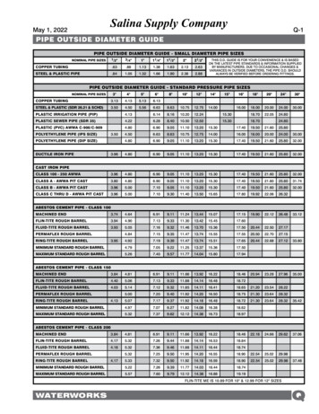
CONNECTING A THERMOCOUPLENote: Be sure your instrument setting (B, N, T, J,K, E, R or S) matches the thermocouple you areusing.Use the correct thermocouple type for your instrument. Using an incorrect thermocouple type willresult in erroneous readings. Thermocouples arecolor coded by type using the North American ANSIColor Code as COLOROrangeGrayGreenGreenThermocouple connectors have one wide blade andone narrow blade. Do not force connector in backwards. Connect thermocouple(s) to receptacle attop of instrument.If only one thermocouple is being used, it can beconnected to either T1 or T2. The thermometer willautomatically determine which connector is beingused. When two thermocouples are used, connectone to the T1 connector and one to the T2connector.Thermocouple wiring polarity must be correct. Ifreadings decrease as the temperature increases,the thermocouple wires may be reversed. The redwire is negative for thermocouple wires manufactured in North America.8
9
10
11
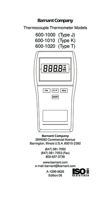
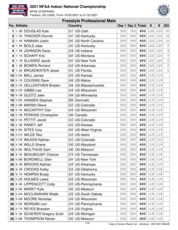
QUICK SETUPNote: Review warnings on page 6.1. Install batteries.2. Connect thermocouple(s).3. Press the ON/OFF key. The thermometer performs a self-test and all display digits and indicators, as shown below, should remain on forapproximately one second. The clock will remainon for about three seconds.4. Use SETUP to select the correct thermocoupleand the desired scale. Use or to makeselections,to enter selections and go tonext step.If a thermocouple has not yet been connected toone or more inputs on the instrument, you will seethis display:This message also appears if a thermocouple isbroken. No measurements can be made while thiswarning is displayed.12
COMPLETE SETUP PROCEDUREThe setup function scrolls through a series of stepsfor selecting thermocouple type, temperature scale,resolution, filter dampening rate, setting the real-timeclock, and accessing the Log sub-menu and the Printsub-menu. Either the complete setup can be run asdescribed below, or the setup can be initiated andterminated at any step. The Log sub-menu and thePrint sub-menu can be accessed without goingthrough the complete setup. These variations arecovered in the following procedures.NOTESettings selected in the Setup procedure are storedin memory and will remain even after power isturned off or while batteries are being replaced.Press the SETUP key. The SETUP and TYPEannunciators will be on and the last selected thermocouple type will be flashing.SELECTING THERMOCOUPLE TYPEPress the MAX key or MIN key to step throughthe eight selections. When the correct thermocouple type is flashing, press theHOLDkey to advance to the next step in thesetup sequence.TEMPERATURE SCALE1. The SETUP and one temperature scale annunciator ( C, F, R, or K) in the upper right handcorner of the display will be flashing.2. Press the MAX key or MIN key to stepthrough the four selections. When the correcttemperature scale is flashing, press thekey to advance to the next step in theHOLDsetup sequence.13
TEMPERATURE RESOLUTIONWhen 0.1 resolution is selected, a decimal pointwill appear in the three numerical displays. When1 resolution is selected, no decimal point will bepresent. When measuring temperature above999.9 or below 150 C, the thermometer automatically autoranges to 1 resolution.The SETUP annunciator will be on. If the instrument is set for 0.1 resolution the decimal point willappear in the display. Press either MAX key orMIN key to change resolution, then press theto advance to the next step in the setupHOLDsequence.FILTER DAMPENINGThe filter dampening rate can be set to OFF orON. This rate is changed to smooth out fluctuations in the readings. Normally this would be set toOFF. If readings are unstable, change to ON.The SETUP annunciator will be on and the lowerleft display will read “FILt” and the upper displaywill flash either OFF or ON. Use the MAX keyor MIN keys to switch the dampening rate, thekey to store the rate and continuepress HOLDsetup by setting the real-time clock.SETTING REAL-TIME CLOCK1. When setting the real-time clock, the SETUPannunciator will be on and the right two digits inthe lower left display will be flashing. Use theMAX key or MIN key to adjust the flashingdigits to the desired minute setting.2. Press HOLDkey to lock in the minutes andadvance to the hours setting.Hours are set in the 24 hour time system. Therefore, time after 12:59 pm requires 12 to be addedto the time. For example, 3:00 PM is (3 12) 15:00 hours.14
3. The SETUP annunciator will be on and the lefttwo digits in the lower left display will be flashing. Use the MAX key or MIN key to adjustthe flashing digits to the desired hour setting.key to store the hours and4. Press the HOLDadvance to the month setting.5. The SETUP and MO annunciators will be onand the right two digits in the lower left displaywill be flashing. Use the MAX key or MIN key to adjust the flashing digits to the desiredmonth setting (1 to 12).6. Press the HOLDkey to store the monthsand advance to the day setting.7. The SETUP and DA annunciators will be onand the right two digits in the lower right display will be flashing. Use the MAX key orMIN key to adjust the flashing digits to thedesired day setting (1 to 31).8. Press HOLDkey to store the day and advance to the year setting.9. The SETUP and YR annunciators will be onand the four digits in the lower right display willbe flashing. Use the MAX key or MIN keyto adjust the flashing digits to the desired yearsetting (1996 to 2059).10. Press HOLDkey to lock in the year. Thiscompletes the basic operation setup and returns to normal operation. To set up the log orprint functions proceed to the following paragraphs.15
LOG SETUPThe Log sub-menu is used to set the time intervalsbetween the logged readings. The time can be setfrom 1 second to 60 minutes. Once the log submenu is setup, logging can be toggled ON or OFFby pressing the LOG key. When logging is turnedON it will continue until turned OFF or 1000 logshave occurred at the entered rate. The first 1000logs are retained.1. Any time while in SETUP, press the LOG key.The SETUP and LOG annunciators will be onand the presently set time interval (default is onesecond) will be displayed in the lower left display. The two right digits represent seconds andwill be blinking.2. Use the MAX key or MIN keys to adjust thekey to“seconds” as desired. Press HOLDstore setting and advance to “minutes” setting.3. Use the MAX key or MIN keys to adjust the“minutes” as desired. Press HOLDkey tostore setting. This completes the Logging setup.PRINT SETUPThe Print sub-menu is used to set the time intervals between the readings being sent to the printer.The default rate is once every three seconds. Thetime can be set from 3 seconds to 60 minutes. Oncethe print sub-menu is setup, printing can be toggledON or OFF by pressing the PRINT key. In additionthe data rate for the infrared RS-232-C output canalso be set.1. Any time the PRINT key is pressed while inSETUP the SETUP and PRINT annunciators willbe on and the presently set time interval (defaultis three seconds) will be displayed in the lowerleft display. The two right digits represent seconds and will be blinking.16
2. Use the MAX key and/or MIN keys to adjust the “seconds” as desired. Press HOLDkey to store setting and advance to the “minutes” setting.3. Use the MAX key and/or MIN keys to adjust the “minutes” as desired. Press HOLDkey to store setting and proceed to the dataoutput rate.4. Use the MAX key and/or MIN keys to scrollthrough the available data output rates of HP,300, or 600, (Use HP for the HEWLETTPACKARD infrared printer). Press HOLDkeyto store setting and end the setup. The data output rates of 300 and 600 are for use with theoptional infrared to RS-232-C adapter.SELECTING INDIVIDUAL PARAMETERSThe thermocouple type, temperature scale, resolution, filter update rate, and real-time clock can beset individually without performing the completesetup. First press the SETUP key, then repeatedlykey until the desired functionpress the HOLDis displayed. Use the keys to change the function and press HOLDkey to store setting.17
OPERATING PROCEDURESThe unit will always power up with the upper display showing T1 unless T1 is not connected. Ifonly T2 is connected at power up, the upper display shows T2 and the lower left display indicatesT1 is open. If thermocouples are not connected toT1 or T2 at power up, the upper display indicatesan open T1 and the lower right display indicates anopen T2.If you are in single probe mode and the probe ismoved to the other connector or to restore the dualprobe mode, turn power OFF then back ON.For optimum operation, allow about one minute forambient temperature stabilization. If the unit hasbeen stored at an extreme ambient condition, moretime may be needed.BASIC TEMPERATURE MEASUREMENTSCheck that the thermometer is turned on, theprobe(s) connected, the desired resolution 0.1 or1 is selected, and the desired scale F, C, R, orK is selected.Single Probe MeasurementsThe thermometer will automatically determine if theT1 or T2 connection is being used.Initially the upper display will indicate the measuredtemperature and the annunciator will indicate whichprobe is making the measurement. One of the lowerdisplays will indicate open and the annunciator willindicate which probe is open. Pressing the T1/T2key will cause the thermometer to go into the singleprobe differential mode described later.Temperatures 999.9 have a resolution of 1 andtherefore no decimal will be present.18
Dual Probe MeasurementsThe thermometer will automatically determine if oneor two thermocouples are connected. When twothermocouples are connected, the upper main display will initially show T1 and the lower right display will show T2. Pressing the T1/T2 key once willcause the upper display to show T2 and the lowerleft display to show T1. Pressing theT1/T2 key again will cause the upper display toshow T1–T2, the lower left display to show T1 andthe lower right display to show T2.MAXIMUM READINGSThe maximum reading function displays the maximum reading since power up or since the last timethe clear function was used. The maximum reading function is ideal for monitoring unattended operations while continually displaying every temperature change that occurs. The maximum and minimum values are sensed and automatically storeduntil you are ready to observe the reading.Do not turn the instrument OFF when a maximumor minimum temperature value may be needed;MAX/MIN memory contents will be lost. FactoryCalibration will be maintained.19
Single Probe MeasurementsThe displayed information depends on whether youare using a single probe in the dual probe mode orhave changed to the single probe differential modeby pressing the T1/T2 key.If you are using a single probe and in the dual probemode, momentarily press the MAX key. TheMAX annunciator turns on. If the probe is connected to T1 the maximum reading will be shownin the lower left display. If the probe is connectedto T2 the maximum reading will be shown in thelower right display. If a higher maximum occurswhile in the MAX mode, the higher reading will bedisplayed. To turn off the maximum reading, pressthe MAX key again.If you are in the single probe differential mode,momentarily press the MAX key. The MAX andMIN annunciators turn on and both the maximumand minimum readings appear in the lower displays.The minimum will be on the left display and themaximum on the right display. If a higher maximum or lower minimum occurs while in the MAXmode, the higher reading will be displayed. To turnoff the maximum reading, press theMAX key again.Dual Probe MeasurementsMomentarily press the MAX key. The MAX annunciator turns on, and both maximum T1 and T2readings appear in the lower display. The T1 reading is on the left display and the T2 reading is onthe right display.Clearing a Maximum ReadingPress the CLEAR key then press the MAX key.The maximum memory will be cleared.20
MINIMUM READINGSThe minimum reading function displays the minimum reading since power up or since the last timethe clear function was used. While continually displaying every temperature change that occurs, themaximum and minimum values are sensed and automatically stored until you are ready to observethe reading.Do not turn the instrument OFF when a maximumor minimum temperature value may be needed;MAX/MIN memory contents will be lost.Single Probe MeasurementsThe displayed information depends on whether youare using a single probe in the dual probe mode orhave changed to the single probe differential modeby pressing the T1/T2 key.If you are using a single probe and in the dual probemode, momentarily press the MIN key. The MINannunciator turns on. If the probe is connected toT1 the minimum reading will be shown in the lowerleft display. If the probe is connected to T2 the minimum reading will be shown in the lower right display. If a lower minimum occurs while in the MINmode, the lower reading will be displayed. To turnoff the minimum reading, press the MIN keyagain.If you are in the single probe differential mode,momentarily press the MIN key. The MAX andMIN annunciators turns on and both the maximumand minimum readings appear in the lower displays.The minimum will be on the left display and themaximum on the right display. If a lower minimumor higher maximum occurs while in the MIN mode,the new readings will be displayed. To turn off theminimum reading, press the MIN key again.21
Dual Probe MeasurementsMomentarily press the MIN key. The MIN annunciator turns on, and both minimum T1 and T2readings appear in the lower display. The T1 reading is on the left display and the T2 reading is onthe right display. Press the MIN key again tocancel.Clearing a Minimum ReadingPress the CLEAR key then the MIN key. Theminimum memory will be cleared.DIFFERENTIAL READINGS (T1-T2)The differential function is used to compare twodifferent measurements and display the differencebetween them. Differential measurements can bemade using either one probe or two probes.Single Probe MeasurementsFor single probe measurements, one measurementis stored as the reference measurement, then eachfollowing measurement is compared to the reference. The reference measurement is viewed on thelower left display, the differential value is shown inthe lower right display and the main display showsthe present T1 or T2 reading.1. Place probe at first measurement point.2. Press the T1/T2 key to store this reference temperature. The T and M annunciators will beon and the reference temperature will be displayed on the lower left display. The T indicatesthat the differential mode is selected and the M indicates that a reference temperature has beenstored. Any time after this that the T1/T2 key ispressed, the M value will be updated to thepresent value shown in the main display.3. Place the probe at the second measurementpoint. The main display will immediately showthe new measured temperature and the lower22
right display will immediately show the differencebetween the reference temperature and thepresent temperature point.Dual Probe Measurement1. Connect the two probes to the two points ofmeasurement. The lower left display will indicatethe T1 temperature, the lower right display willindicate the T2 temperature.2. The main display can be scrolled between displaying T1, T2 or the differential temperature T1T2 by repeatedly pressing the T1/T2 key. To display the differential temperature press the T1/T2key until the T1-T2 annunciator to the right ofthe main display is on.HOLD FUNCTIONkey to retain the reading onPress the HOLDthe display. Press HOLDkey again for normaloperation.Maximum HoldPress the MAX key, then press theHOLDkey. To turn off the HOLD function andreturn to normal operation, press the HOLDkeyagain.To clear the maximum readings, press the CLEARkey, then the MAX key.Minimum HoldPress the MIN key, then press the HOLDkey. To turn off the HOLD function and return tonormal operation press the HOLDkey again.To clear the minimum readings, press the CLEARkey, then the MIN key.23
STORED READINGSThe store function allows you to store up to 1000readings. Each reading is logged with a storagelocation number and the time of occurrence. BothT1 and T2 readings are stored. To store readingsproceed as follows:1. Momentarily press the STORE key. Both T1 andT2 are stored. The upper main display will momentarily show the storage location number andthe STO annunciator will be on.After three seconds the storage number will be replaced with a temperature reading but the STOannunciator remains on to indicate a temperaturereading has been stored. The STORE key may bepressed as fast as once per second.2. Repeat step 1 for all the points to be recordedup to a maximum of 1000. Each time the STOREkey is pressed the new reading will be storedand the upper main display will show the storage location number for about 3 seconds. After1000 stored readings, the next time the STOREkey is pressed the main display will indicateFULL.RECALL READINGSThis function allows the stored readings and theTime/Date of the readings to be recalled. RECALLshows each stored reading individually. When individual readings are recalled you can toggle betweenthe reading and the time/date of the reading. To recall readings proceed as follows:1. Momentarily press the RECALL key, the firststored reading will be displayed on the lower display and the stored sequence number will bedisplayed on the upper main display. The STOand RCL annunciators will be on.24
2. To step through the readings, press the MAX key or the MIN key. Each press of the key willadvance to the next reading in sequence. Holdthe MAX key or MIN key down to continuously advance through the readings at an increasing rate. To increment or decrement by 100proceed as follows:To increment hold down the MAX key thenpress the MIN key.To decrement hold down the MIN key thenpress the MAX key.3. To toggle between the readings and the time ofthe readings press the RECALL key again.4. To return to normal operation press any otherkey except ON/OFF, MAX , MIN or RECALL.CLEARING STORED OR LOGGED READINGSPress the CLEAR key, then the STORE key orLOG key. Regardless of which key is pressed,STORE or LOG, the stored and logged readingsin memory will be cleared.LOGGING READINGSThe Logging function is controlled by the LOG key.Prior to logging readings it is necessary to set upthe time interval between readings (see LOG Setup)in COMPLETE SETUP PROCEDURE section.The time between readings can be set to any valuefrom 1 second to 60 minutes. Logging is initiatedby pressing the LOG key. Logging will continue atthe programmed rate until either the LOG key ispressed again or 1000 logs have occurred. Thedisplay will then show "FULL".The STORE function can be used during loggingto insert additional measurements by pressing theSTORE key.25
PRINTINGPrinting can output real-time readings or storedreadings. The output is sent to the infrared (IR)printer output located at the top of the thermometer. The printer output default time period is onceevery 3 seconds. This time can be set to any valuebetween 3 seconds and 60 minutes (see PRINTSetup) in the COMPLETE SETUP PROCEDUREsection. The following sample printouts show theRS-232-C format and the HEWLETT-PACKARDinfrared printer in normal and log dump print modes.Note that in log dump print mode the first line specifies the total number of readings.HP Printer Format for Normal PrintingNew heading will appear when date changes ornew print is started.---- over range05/21/96 T1 F T2 F10:33:25 902.3 904.410:33:30 902.3 904.410:33:352504250410:33:40 "----"250410:33:45 100.0 - 17.810:33:50 100.0 - 17.810:33:55 100.0OPEN26
HP Printer Format for Log DumpNew heading will appear when date changes.---- over rangeTOTAL READINGS:705/21/96 T1 F T2 F10:33:25 902.3 904.410:33:30 902.3 904.410:33:352504250410:33:40 "----" 250410:33:45 100.0 - 17.810:33:50 100.0 - 17.810:33:55 100.0OPENNote that printing 1000 stored sets of readings couldtake nearly one hour as limited by the printer.RS-232-C Format for Normal Printingand Log Dump---- over range,,"T1 F","T2 F"05/21/96,10:31:25, 164.4, 165.8,10:31:30, 164.2, 165.1,10:31:35,"OPEN", 165.1,10:31:40,"OPEN","OPEN",10:31:45,- 65.7, 165.1,10:31:50, 2507, 165.1,10:31:55, 2507, 165.2,10:32:00,"----", 165.2,10:32:05,"----", 165.227
The print function is controlled by the PRINT key.Proceed as follows:1. Perform the PRINT Setup procedure to set thedesired print rate.2. Check that the IR printer input is properly alignedwith the infrared output at the top of thethermometer.Printer output will occur in real-time when the thermometer is operating in the normal mode. Whenthe thermometer is in the RECALL mode, printingof the stored information will occur.3. Press the PRINT key to start printing. Printingwill continue at the programmed print rate untilthe PRINT key is pressed again, or if stored datais being printed, all data has been transferred tothe printer. When printing stored data, thetemperatures and times of occurrence will beoutput.28
CALIBRATIONThe calibration function allows both single point anddual point calibration of the thermometer. Singlepoint calibrates the offset only. Dual point calibratesthe offset first then calibrates the slope. The thermometer can be calibrated at any temperature.When two probes are used, a match calibrationmatches the T1 and T2 offsets.It is not necessary to perform a field calibration toobtain specified accuracies. Use the field calibration feature to improve thermometer/probe accuracy or to compensate for thermocouple probe calibration drift.The thermometer has a memory retention capability to hold calibration values even while power isoff or the battery is removed.When you restart, there is no need to recalibrate.Each of the eight thermocouple types may be individually calibrated and stored.NOTEThe temperature at which water boils (100 C/212 F) is at sea level and standard atmosphericpressure using distilled water. Changes in altitudeand barometric pressure will cause the boiling temperature to change.As a rule of thumb, the boiling temperature of water will decrease 1 C (1.8 F) for every 1000 feetabove sea level. For example, at an elevation of5300 feet (1600 meters), water will boil at approximately 94.7 C (202.5 F).Other liquids may also be used as calibration standards. Consult a chemical handbook for their freezing (melting) point and boiling point properties.29
When calibrating at freezing (0 C or 32 F) it is recommended to use crushed ice made of distilledwater in a dewar flask. Add crushed ice to top offlask. Top off flask with distilled water. Continue toadd crushed ice to maintain tightly packed crushedice/water in flask.CALIBRATION PROCEDURESCalibration Procedure (One Probe Detected)This calibration function provides for both an offsetand slope field calibration of either T1 or T2. If onlyone probe is detected, the procedure applies to thatprobe, and the main display will indicate T1 or T2as applicable. For proper calibration the followingconditions must be observed: The slope point must be a higher temperature thanthe offset point. The difference must be at least 20 C. Use two points based on the expected high andlow temperatures. Temperatures measured outside of these limits may no longer meet specifications.Proceed as follows to calibrate the probes.1. Place the probe at the lower known referencetemperature.2. Offset Calibration: Momentarily press the CALkey to enter the calibration mode, the CAL annunciator will flash. The temperature is displayedon the main display and Lo is displayed on
THERMOCOUPLE THERMOMETER MODEL NO. 600-1050 Barnant Company 28W092 Commercial Avenue Barrington, Illinois U.S.A. 60010-2392 (847) 381-7050 (847) 381-7053 (Fax) 800-637-3739 www.barnant.com e-mail: barnant@barnant.com A-1299-0631 Edition 07. CERTIFICATE OF CONFORMANCE This thermometer was calibrated using equipment traceable to the National .