Transcription
Database SystemsSession 4 – Main ThemePractical Relational Database DesignDr. Jean-Claude FranchittiNew York UniversityComputer Science DepartmentCourant Institute of Mathematical SciencesPresentation material partially based on textbook slidesFundamentals of Database Systems (6th Edition)by Ramez Elmasri and Shamkant NavatheSlides copyright 20111Agenda11SessionSession OverviewOverview22ERER andand EEREER toto RelationalRelational MappingMapping33DatabaseDatabase DesignDesign MethodologyMethodology andand UMLUML44MappingMapping RelationalRelational DesignDesign toto ER/EERER/EER CaseCase StudyStudy55SummarySummary andand ConclusionConclusion2
Session Agenda Session Overview ER and EER to Relational Mapping Database Design Methodology and UML Mapping Relational Design to ER/EER Case Study Summary & Conclusion3What is the class about? Course description and syllabus:» http://www.nyu.edu/classes/jcf/CSCI-GA.2433-001» http://cs.nyu.edu/courses/fall11/CSCI-GA.2433-001/ Textbooks:» Fundamentals of Database Systems (6th Edition)Ramez Elmasri and Shamkant NavatheAddition WesleyISBN-10: 0-1360-8620-9, ISBN-13: 978-0136086208 6th Edition (04/10)4
Icons / MetaphorsInformationCommon RealizationKnowledge/Competency PatternGovernanceAlignmentSolution Approach55Agenda11SessionSession OverviewOverview22ERER andand EEREER toto RelationalRelational MappingMapping33DatabaseDatabase DesignDesign MethodologyMethodology andand UMLUML44MappingMapping RelationalRelational DesignDesign toto ER/EERER/EER CaseCase StudyStudy55SummarySummary andand ConclusionConclusion6
AgendaSetsRelations and tablesRelational schemaPrimary keysRelational Database Design Using ER-to-RelationalMapping Mapping EER Model Constructs to Relations Design a relational database schema Based on a conceptual schema design Seven-step algorithm to convert the basic ER modelconstructs into relations Additional steps for EER model7Sets, Relations, and Tables In this unit, we learn the semantics of specifying arelational database, later we will learn the syntax of SQLfor doing this The basic “datatype”, or “variable” of a relationaldatabase is a relation In this unit, such a variable will be a set Later, we will extend this, and such a variable will be amultiset In SQL, such a variable is called a table We may use the term table for a relation in this unit too8
Sets We will not use axiomatic set theory A set is a “bag” of elements, some/all of which could besets themselves and a binary relationship “is elementof” denoted by , such as 2 {2, 5, 3, 7}, {2,8} {2, {2,8}, 5, 3, 7}, You cannot specify» How many times an element appears in a set (if you could, thiswould be a multiset)» In which position an element appears (if you could, this wouldbe a sequence) Therefore, as sets: {2, 5, 3, 7} {2, 7, 5, 3, 5, 3, 3} Note: in many places you will read: “an element canappear in a set only once”This is not quite right. And it is important not to assumethis, as we will see in the next unit9Sets Two sets A and B are equal iff (if and only if) they have thesame elements In other words, for every x: x is an element of A iff (if andonly if) x is an element of B “More mathematically,” x { x A x B } if and only if A B Therefore, as sets: {2, 5, 3, 7} {2, 7, 5, 3, 5, 3, 3} This reiterates what we have said previously10
Relation Consider a table, with a fixed number of columns where elementsof each column are drawn from some specific domainThe columns are labeled and the labels are distinctWe will consider such a table to be a set of rows (another word for“row”: tuple)Here is an example of a table S of two columns A and BSAaabcd B22343A relation is such a tableWe will also write S(A,B) for table S with columns A and B11Relational Schema What we saw was an instance (current valuefor a relation with the defined columns anddomains) To specify this relation in general (not thespecific instance) we need to talk about arelational schema A relational schema defines a constant numberof relations, one or more12
Relational Schema Here is an informal, but complete, description what is arelational schema of one relation We want to define a structure for some table1. We give it a name (we had S)2. We chose the number of columns (we had 2) and givethem distinct names (we had A and B)3. We decide on the domains of elements in the columns(we had letters for A and integers for B)4. We decide on constraints, if any, on the permittedvalues (we had that any two rows that are equal on Amust be equal on B)13Relational Schema Let’s verify» A all lower case letters in English» B all positive integers less than 100» S(A,B) satisfies the condition that any two tuples thatare equal on A must also be equal on B Our example was an instance of this relationalschemaSAaabcdB2234314
Relations (1/8) Since relations are sets of tuples, the followingtwo relations are equal (are really one relationwritten in two different ways)(This is a different example, not an instance ofthe previous relational schema)SSABaabAB562256256aabaaa256215Relations (2/8) Since the positions in the tuple (1st, 2nd, etc.)are labeled with the column headings, thefollowing two relations are equal (are reallyone relation written in two different ways)SAaabB2562SB562256256Aaabaaa16
Relations (3/8) To specify relations, it is enough to do what wehave done above As long as we understand what are the domainsfor the columns, the following are formally fullyspecified relations» Relational (schema) P(Name, SSN, DOB, Grade)with some (not specified, but we should have done it)domains for attributes» Relational (schema) Q(Grade, Salary) with some(not specified, but we should have done it) domainsfor 280B10134984370C1062987247017Relations (4/8) But we will do more. We will specify, asappropriate for the schema:» Primary keys» Keys (beyond primary)» Foreign keys and what they reference (we will seesoon what this means)» Additional constraints Some of the constraints involve more than onerelation The above most important structurally Later, when we talk about SQL DDL, we willspecify additional properties18
Relations (5/8) Consider relation (schema) Person(FN, LN, Grade, YOB)Instance:Person YOB1976198119761992We are told that any two tuples that are equal on both FN and LNare (completely) equal» We have some tuples appearing multiple times: this is just for clarifyingthat this permitted in the definition, we do not discuss here why wewould have the same tuple more than one time (we will talk about thislater) This is a property of every possible instance of Person in ourapplication—we are told thisThen (FN, LN) is a superkey of Person, and in fact a key, becauseneither FN nor LN by themselves are sufficient (we are told thattoo)19Relations (6/8) Consider relation (schema) Q(Grade, Salary) Example:PayGradeSalary812891397147 We are told that for any instance of Pay, any two tuplesthat are equal on Grade are (completely) equal» Of course, if each Grade appears in only one tuple, this isautomatically true Then, similarly to before, Grade is a key What about Salary, is this a key also? No, because we are not told that any two tuples thatare equal on Salary are equal on Grade in everyinstance of Pay20
Relations (7/8) A set of columns in a relation is a superkey if and only any twotuples that are equal on the elements of these columns are(completely equal)A relation always has at least one superkeyThe set of all the attributes is a superkeyBecause any two tuples that are equal on all attributes arecompletely equalA minimal superkey, is a keyA relation always has at least one key (start with any superkey andremove unnecessary columns)There may be more than one keyExactly one key is chosen as primary keyOther keys are just keysSometimes they are called candidate keys (as they are candidatesfor the primary key, though not chosen)21Relations (8/8) We will underline the attributes of the chosen primarykey Returning to the City ,Size) We can have» City(Longitude,Latitude,Country,State,Name,Size)» This implies that Longitude,Latitude form a primary key» We also have a candidate key: Country,State,Name We can have» City(Longitude,Latitude,Country,State,Name,Size)» This implies that Country,State,Name form a primary key» We also have a candidate key: Longitude,Latitude22
Relational Databases A relational database is basically a set ofrelations and is an instance of a relationalschema23Relational Database Design Using ER-to-Relational Mapping24
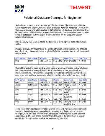
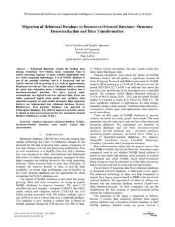
Sample Mapping of ER Schema to Relational Database Schema25ER-to-Relational Mapping Algorithm (1/9) COMPANY database example Assume that the mapping will create tables with simplesingle-valued attributes Step 1: Mapping of Regular Entity Types For each regular entity type, create a relation R thatincludes all the simple attributes of E Called entity relations Each tuple represents an entity instance26
ER-to-Relational Mapping Algorithm (2/9) Step 2: Mapping of Weak Entity Types For each weak entity type, create a relation R andinclude all simple attributes of the entity type asattributes of R Include primary key attributes of owner as foreign keyattributes of R27ER-to-Relational Mapping Algorithm (3/9)28
ER-to-Relational Mapping Algorithm (4/9) Step 3: Mapping of Binary 1:1 Relationship Types For each binary 1:1 relationship type Identify relations that correspond to entity types participating inR Possible approaches: Foreign key approach Merged relationship approach Crossreference or relationship relation approach29ER-to-Relational Mapping Algorithm (5/9) Step 4: Mapping of Binary 1:N Relationship Types For each regular binary 1:N relationship type Identify relation that represents participating entity type at Nside of relationship type Include primary key of other entity type as foreign key in S Include simple attributes of 1:N relationship type as attributesof S30
ER-to-Relational Mapping Algorithm (6/9) Alternative approach Use the relationship relation (cross-reference)option as in the third option for binary 1:1relationships31ER-to-Relational Mapping Algorithm (7/9) Step 5: Mapping of Binary M:N RelationshipTypes For each binary M:N relationship type Create a new relation S Include primary key of participating entity types as foreign keyattributes in S Include any simple attributes of M:N relationship type32
ER-to-Relational Mapping Algorithm (8/9) Step 6: Mapping of Multivalued Attributes For each multivalued attribute Create a new relation Primary key of R is the combination of A and K If the multivalued attribute is composite, include its simplecomponents33ER-to-Relational Mapping Algorithm (9/9) Step 7: Mapping of N-ary Relationship Types For each n-ary relationship type R Create a new relation S to represent R Include primary keys of participating entity types as foreignkeys Include any simple attributes as attributes34
Discussion and Summary of Mapping for ER Model Constructs (1/2)35Discussion and Summary of Mapping for ER Model Constructs (2/2) In a relational schema relationship, types are notrepresented explicitly Represented by having two attributes A and B: one aprimary key and the other a foreign key36
Mapping EER Model Constructs to Relations Extending ER-to-relational mapping algorithm37Mapping of Specialization or Generalization (1/2) Step 8: Options for Mapping Specialization orGeneralization (see textbook pages 294-295) Option 8A: Multiple relations—superclass andsubclasses For any specialization (total or partial, disjoint or overlapping) Option 8B: Multiple relations—subclass relationsonly Subclasses are total Specialization has disjointedness constraint38
Mapping of Specialization or Generalization (2/2) Option 8C: Single relation with one type attribute Type or discriminating attribute indicates subclass of tuple Subclasses are disjoint Potential for generating many NULL values if many specificattributes exist in the subclasses Option 8D: Single relation with multiple typeattributes Subclasses are overlapping Will also work for a disjoint specialization39Mapping of Shared Subclasses (Multiple Inheritance) Apply any of the options discussed in step 8 to ashared subclass40
Mapping of Categories (Union Types) Step 9: Mapping of Union Types (Categories) Defining superclasses have different keys Specify a new key attribute Surrogate key41Sample Mapping of EER Categories to Relations42
Summary Map conceptual schema design in the ER modelto a relational database schema Algorithm for ER-to-relational mapping Illustrated by examples from the COMPANY database Include additional steps in the algorithm formapping constructs from EER model intorelational model43Agenda11SessionSession OverviewOverview22ERER andand EEREER toto RelationalRelational MappingMapping33DatabaseDatabase DesignDesign MethodologyMethodology andand UMLUML44MappingMapping RelationalRelational DesignDesign toto ER/EERER/EER CaseCase StudyStudy55SummarySummary andand ConclusionConclusion44
Agenda The Role of Information Systems inOrganizations The Database Designand Implementation Process Use of UML Diagrams as an Aid to DatabaseDesign Specification Rational Rose: A UML-Based Design Tool Automated Database Design Tools45Practical Database Design Methodology and Use of UML Diagrams Design methodology Target database managed by some type of databasemanagement system Various design methodologies Large database Several dozen gigabytes of data and a schema withmore than 30 or 40 distinct entity types46
The Role of Information Systems in Organizations (1/3) Organizational context for using databasesystems Organizations have created the position of databaseadministrator (DBA) and database administrationdepartments Information technology (IT) and information resourcemanagement (IRM) departments Key to successful business management47The Role of Information Systems in Organizations (2/3) Database systems are integral components incomputer-based information systems Personal computers and database system-likesoftware products Utilized by users who previously belonged to thecategory of casual and occasional database users Personal databases gaining popularity Databases are distributed over multiplecomputer systems Better local control and faster local processing48
The Role of Information Systems in Organizations (3/3) Data dictionary systems or informationrepositories Mini DBMSs Manage meta-data High-performance transaction processingsystems require around-the-clock nonstopoperation Performance is critical49The Information System Life Cycle (1/4) Information system (IS) Resources involved in collection, management, use,and dissemination of information resources oforganization50
The Information System Life Cycle (2/4) Macro life cycle Feasibility analysisRequirements collection and analysisDesignImplementationValidation and acceptance testingRequirements collection and analysis51The Information System Life Cycle (3/4) The database application system life cycle: microlife cycle System definitionDatabase designDatabase implementationLoading or data conversion52
The Information System Life Cycle (4/4) Application conversionTesting and validationOperationMonitoring and maintenance53The Database Design and Implementation Process (1/4) Design logical and physical structure of one ormore databases Accommodate the information needs of the users in anorganization for a defined set of applications Goals of database design Very hard to accomplish and measure Often begins with informal and incompleterequirements54
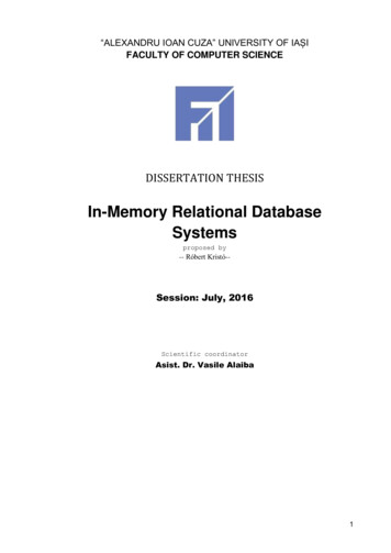
The Database Design and Implementation Process (2/4) Main phases of the overall database design andimplementation process:1. Requirements collection and analysis2. Conceptual database design3. Choice of a DBMS4. Data model mapping (also called logical databasedesign) 5. Physical database design 6. Database system implementation and tuning 55Phases of Database Design and Implementation for Large Databases56
The Database Design and Implementation Process (3/4) Parallel activities Data content, structure, and constraints of thedatabase Design of database applications Data-driven versus process-driven design Feedback loops among phases and withinphases are common57The Database Design and Implementation Process (4/4) Heart of the database design process Conceptual database design (Phase 2)Data model mapping (Phase 4)Physical database design (Phase 5)Database system implementation and tuning(Phase 6)58
Phase 1: Requirements Collection and Analysis (1/2) Activities Identify application areas and user groupsStudy and analyze documentationStudy current operating environmentCollect written responses from users59Phase 1: Requirements Collection and Analysis (2/2) Requirements specification techniques Oriented analysis (OOA)Data flow diagrams (DFDs)Refinement of application goalsComputer-aided60
Phase 2: Conceptual Database Design (1/3) Phase 2a: Conceptual Schema Design Important to use a conceptual high-level data model Approaches to conceptual schema design Centralized (or one shot) schema design approach View integration approach61Phase 2: Conceptual Database Design (2/3) Strategies for schema design Top-down strategyBottom-up strategyInside-out strategyMixed strategy Schema (view) integration Identify correspondences/conflicts among schemas: Naming conflicts, type conflicts, domain (value set)conflicts, conflicts among constraints Modify views to conform to one another Merge of views and restructure62
Phase 2: Conceptual Database Design (3/3) Strategies for the view integration process Binary ladder integrationN-ary integrationBinary balanced strategyMixed strategy Phase 2b: Transaction Design In parallel with Phase 2aSpecify transactions at a conceptual levelIdentify input/output and functional behaviorNotation for specifying processes63Phase 3: Choice of a DBMS Costs to consider Software acquisition costMaintenance costHardware acquisition costDatabase creation and conversion costPersonnel costTraining costOperating cost Consider DBMS portability among different typesof hardware64
Phase 4: Data Model Mapping (Logical Database Design) Create a conceptual schema and externalschemas In data model of selected DBMS Stages System-independent mapping Tailoring schemas to a specific DBMS65Phase 5: Physical Database Design Choose specific file storage structures andaccess paths for the database files Achieve good performance Criteria used to guide choice of physical databasedesign options: Response time Space utilization Transaction throughput66
Phase 6: Database System Implementation and Tuning Typically responsibility of the DBA Compose DDL Load database Convert data from earlier systems Database programs implemented by applicationprogrammers Most systems include monitoring utility to collectperformance statistics67Use of UML Diagrams as an Aid to Database Design Specification Use UML as a design specification standard Unified Modeling Language (UML) approach Combines commonly accepted concepts from manyobject-oriented (O-O) methods and methodologies Includes use case diagrams, sequence diagrams,and statechart diagrams68
UML for Database Application Design Advantages of UML Resulting models can be used to design relational,object-oriented, or object-relational databases Brings traditional database modelers, analysts, anddesigners together with software applicationdevelopers69Different Types of Diagrams in UML (1/4) Structural diagrams Class diagrams and package diagramsObject diagramsComponent diagramsDeployment diagrams70
Different Types of Diagrams in UML (2/4) Behavioral diagrams Use case diagramsSequence diagramsCollaboration diagramsStatechart diagramsActivity diagrams71Use Case Diagram Notation72
Different Types of Diagrams in UML (3/4)73Different Types of Diagrams in UML (4/4)74
Modeling and Design Example: UNIVERSITY Database75Sample Sequence Diagram76
Sample Class Diagram77Rational Rose: A UML-Based Design Tool Rational Rose for database design Modeling tool used in the industry to developinformation systems Rational Rose data modeler Visual modeling tool for designing databases Provides capability to: Forward engineer a database Reverse engineer an existing implemented database intoconceptual design78
Data Modeling Using Rational Rose Data Modeler (1/4) Reverse engineering Allows the user to create a conceptual data modelbased on an existing database schema specified in aDDL file Forward engineering and DDL generation Create a data model directly from scratch in Rose Generate DDL for a specific DBMS79Data Modeling Using Rational Rose Data Modeler (2/4) Conceptual design in UML notation Build ER diagrams using class diagrams in RationalRose Identifying relationships Object in a child class cannot exist without a correspondingparent object Non-identifying relationships Specify a regular association (relationship) between twoindependent classes80
Data Modeling Using Rational Rose Data Modeler (3/4) Converting logical data model to object modeland vice versa Logical data model can be converted to an objectmodel Allows a deep understanding of relationships betweenconceptual and implementation models81Data Modeling Using Rational Rose Data Modeler (4/4) Synchronization between the conceptual designand the actual database Extensive domain support Create a standard set of user-defined data types Easy communication among design teams Application developer can access both the object anddata models82
Automated Database Design Tools (1/3) Many CASE (computer-aided softwareengineering) tools for database design Combination of the following facilities Diagramming Model mapping Design normalization83Automated Database Design Tools (2/3) Characteristics that a good design tool shouldpossess: Easy-to-use interfaceAnalytical componentsHeuristic componentsTrade-off analysisDisplay of design resultsDesign verification84
Automated Database Design Tools (3/3) Variety of products available Some use expert system technology85Summary Six phases of the design process Commonly include conceptual design, logical design(data model mapping), physical design UML diagrams Aid specification of database models and design Rational Rose and the Rose Data Modeler Provide support for the conceptual design and logicaldesign phases of database design86
Agenda11SessionSession OverviewOverview22ERER andand EEREER toto RelationalRelational MappingMapping33DatabaseDatabase DesignDesign MethodologyMethodology andand UMLUML44MappingMapping RelationalRelational DesignDesign toto ER/EERER/EER CaseCase StudyStudy55SummarySummary andand ConclusionConclusion87A Case Study Implementing an ER diagram as a relational schema (relationaldatabase)General implementation of strong entitiesHandling attributes of different typesGeneral implementation of relationshipsPossible special implementation of binary many-to-onerelationshipsImplementation of ISAImplementation of weak entities Foreign keysPrimary key / foreign key constraints inducing many-to-onerelationships between tablesConcept of referential integrityCrow’s feet notation: ends of linesCrow’s feet notation: pattern of lines88
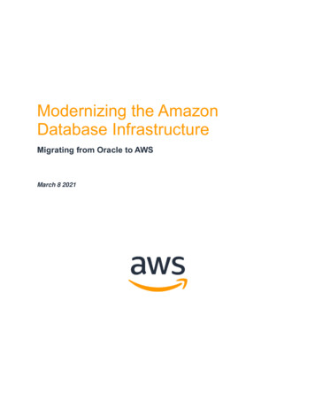
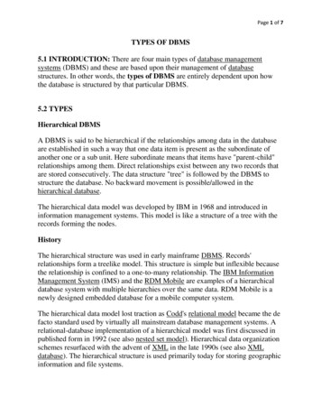
From ER Diagrams To Relational Database We are now ready to convert ER diagrams intorelational databases Generally, but not always» An entity set is converted into a table» A relationship is converted into a table We will first go through a simple example Then, we will go through our large example, studiedpreviously Then, we look at some additional points of interest Finally, we summarize the process, so we are sure weunderstand it89Small ER Diagram90
More About The Example The given ER diagram is clear, other than» Discovered, which is the continent in which a particular species wasfirst discovered Each child is a “dependant” of only one employee in our database» If both parents are employees, the child is “assigned” to one of them We are given additional information about the application» Values of attributes in a primary key must not be missing (this is ageneral rule, not only for this example)» Other than attributes in a primary key, other attributes unless statedotherwise may be missing» The value of Name is known for every Employee To build up our intuition, let’s look at some specific instance of ourapplication91Country There are four countries, listing for them:Cname, Population (the latter only whenknown):CountryCnamePopulation» US» IN, 1150» CN, 1330» RUUSIN1150CN1330RU We create a table for Country “in the mostobvious way,” by creating a column foreach attribute (underlying the attributesof the primary key) and this works:92
Animal There are five animals, listing for them:Species, Discovered (note, that eventhough not required, Discovered happensto be known for every Species):» Horse, Asia» Wolf, Asia» Cat, Africa» Yak, Asia» Zebra, fricaYakAsiaZebraAfrica We create a table for Animal as before,and this works:93Employee There are five employees, listing for them: ID#, Name, (name of)Child (note there may be any number of Child values for anEmployee, zero or more):»»»»» 1, Alice, Erica, Frank2, Bob, Bob, Frank4, Carol5, David6, Bob, FrankWe create a table for Employee in the most obvious way, and thisdoes not BobFrank4Carol5David6BobFrank94
Employee Child is a multivalued attribute so, the number ofcolumns labeled “Child” is, in principle, unbounded A table must have a fixed number of columns» It must be an instance in/of a relational schema If we are ready to store up to 25 children for anemployee and create a table with 25 columns forchildren, perhaps tomorrow we get an employee with 26children, who will not “fit” We replace our attempted single table for Employeeby two tables» One for all the attributes of Employee other than the multivaluedone (Child)» One for pairs of the form (primary key of Employee, Child) Note that both tables have a fixed number of columns,no matter how many children an employee has95Employee And Child Replace (incorrect)EmployeeID#12456EmployeeID#12456By 11226ChildEricaFrankBobFrankFrank96
Employee And Child The primary key of the table Employee is ID# The primary key of the table Child is the pair: ID#,Child One attribute is not sufficient to get a primary key forChild It is clear from the example how to handle any numberof multivalued attributes an entity has» Create a “main” table with all the attributes other thanmultivaluedIts primary key is the original primary key of the entity set» Create a table for each multivalued attribute consisting aprimary key for the main table and that multivaluedattributeIts primary key is the primary key of the entity combined withthe multivalued attribute97Foreign Key Let us return to our exampleNote that any value of ID# that appears in Child must also appearin Employee This is an instance of a foreign keyID# in Child is a foreign key referencing Employee» Because a child must be a dependant of an existing employee» This means that ID# appearing in Child must appear in some row“under” columns (here only one) of primary key in Employee» Note that ID# is not a key of Child, so a foreign key in a table doesnot have to be a key of that dID#11226ChildEricaFrankBobFrankFrank98
Foreign Key Induces A Many-To-One Relationship Between Tables Note:» Every row of Child has a single value of a primarykey of Employee, so every row of Child “maps” to asingle row of Employee» Every row of Employee has zero or more rows ofChild mapped into itIn other words, no constraint99Likes (1/3) Likes needs to specify which employees likewhich animals Such specification can be done using theprimary keys of the entitiesWe do not need other attributes such as Nameor Discovered The table for likes contains some tuples:»»»»1 likes Horse1 likes Cat2 likes Cat6 likes YakLikesID#Species1Horse1Cat2Cat6Yak100
Likes (2/3) We could phrase the above somewhat differently Likes needs to specify which employees (as rows intable Employee) like which animals (as rows in tableAnimal) Such a specification can done using the primarykeys of the tables Employee and Animal The table for Likes contains some tuples:»»»»1 likes Horse1 likes Cat2 likes Cat6 likes YakLikesID#Species1Horse1Cat2Cat6Yak101Likes (3/3) Note that there are foreign key constraints» ID# appearing in Likes is a foreign key referencing Employee» Species appearing in Likes is a foreign key referencing Animal And two many-to-one mappings are induced This is true whenever we build a table for a relationship» Likes was a relationship in the ER diagram102
Born (1/3) Born needs to specify which employeeswere born in which countries (for whomthis information is known) Such specification can done using theprimary keys of the entities/tables The relation Born contains some tuples:» 1, US» 2, IN» 5, IN» 6, CNBornID#Cname1US2IN5IN6CN103Born (2/3) Note that there are foreign key constraints» ID# appearing in Born is a foreign key referencing Employee» Cname appearing in Born is a foreign key referencing Country And two many-to-one mappings are induced» One of them happens to be one-to-one as an employee can be born inonly one country» This follows from the fact that in
Sample Mapping of ER Schema to Relational Database Schema 26 ER-to-Relational Mapping Algorithm (1/9) COMPANY database example Assume that the mapping will create tables with simple single-valued attributes Step 1: Mapping of Regular Entity Types For each regular entity type, create a relation R that includes all the simple attributes of E